B | Quantities and Equations
This appendix brings together the most important reference material from throughout the book in one place. Important quantities are listed in Table B.1, along with the standard symbols used to represent them in equations, and the units in which they are measured.
Quantity |
Units |
Notes |
||
Impedance |
(Z) |
Ohm |
(Ω) |
also Resistance (R) and Reactance (X) |
Voltage |
(V) |
Volt |
(V) |
aka EMF, PD |
Current |
(I) |
Amp |
(A) |
aka Ampere |
Power |
(P) |
Watt |
(W) |
also Apparent power (VA) |
Charge |
(Q) |
Coulomb |
(C) |
also Amp-hour (1Ah = 3,600C) |
Frequency |
(f) |
Hertz |
(Hz) |
aka Cycles per second (cps) |
Capacitance |
(C) |
Farad |
(F) |
|
Inductance |
(L) |
Henry |
(H) |
plural Henries |
Statements of useful rules and laws are provided in order to facilitate the straightforward analysis of simple electronic circuits and systems. The chapters where each group of equations is introduced are identified in the section headings. The index which follows these appendices can be used to guide the reader to more detailed information on the theory and the application of the individual rules and laws presented.
Primary Quantities
Decibel Equations
(see Chapter 5 – Signal Characteristics)
| For power | and | ||
| For voltage | and | ||
| Reference levels | 0dBu = 0.775V | +4dBu = 1.23V | |
| 0dBV = 1.0V | −10dBV = 0.316V | ||
Fundamental Laws
(see Chapter 9 – Basic Circuit Analysis)
| Ohm’s law | V = I × R | |
| Watt’s law | ||
| Kirchoff’s current law (KCL) | Iin = Iout | Currents into a point equal currents out |
| Kirchoff’s voltage law (KVL) | Vo = 0 | Voltage drops around any loop equal zero |
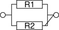
Resistor Equations
(see Chapter 12 – Resistors)
RLC Equations
(see Chapter 13 – Capacitors and Inductors)
Capacitors in series |
(F) |
|
Capacitors in parallel |
(F) |
Cparallel = C1 + C2 |
Inductors in series |
(H) |
Lparallel = L1 + L2 |
Inductors in parallel |
(H) |
|
Capacitor reactance |
(Ω) |
|
Inductor reactance |
(Ω) |
XL = 2πfL |
RLC series rule |
(Ω) |
|
LC series rule |
(Ω) |
|Zseries| = |XL − XC| |
RLC parallel rule |
(Ω) |
|
LC parallel rule |
(Ω) |
|
RC time constant |
(sec) |
τ = RC |
RL time constant |
(sec) |
|
RC cutoff frequency |
(Hz) |
|
RL cutoff frequency |
(Hz) |
|
LC resonance frequency |
(Hz) |
|
LC characteristic impedance |
(Ω) |
Transformer Equations
(see Chapter 14 – Transformers)
| Turns ratio | |
| Power transfer | Psec = Ppri |
| Voltage transformation | Vsec = k × Vpri |
| Current transformation | |
| Impedance transformation | Zsec = k2 × Zpri |
Opamp Equations
(see Chapter 18 – Integrated Circuits)
Open-loop transfer function |
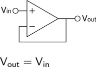
Voltage follower transfer function |
|
|
Inverting configuration |
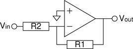
Noninverting configuration |
|
|
Gain equation: |
Gain equation: |
Transfer function: Vout = g × Vin |
Transfer function: Vout = g × Vin |