
7
Materials Production
7.1 Introduction
Manufacturing processes are the means used to change a material from one state to another state of higher value. For example, iron ore is smelted to make pig iron that is converted to make steel. Next, the steel might be continuous cast before rolling to make sheet steel. This can be blanked to make car body frames; these frames are then assembled to other components to produce a finished car.
Although manufacturing is a secondary industry, it relies on primary industries such as mining and quarrying to supply the raw materials. Some materials used by manufacturing industry were examined in Chapter 6; in this chapter, we will look at the production of the metals iron, steel, copper and aluminium, and also basic polymer production. Most metals require to be mined since they are found in naturally occurring mineral deposits known as ‘ores’. In the natural state the metals are usually combined with other, undesired, elements. This ‘gangue’, is removed to leave the concentrated ore ready for the metal extraction process.
7.2 Ferrous Metals Production
7.2.1 Pig Iron
Pig iron is the initial raw material for all ferrous metals. The composition of the pig iron will determine how it will be used. Along with iron the alloys usually contain between 3 and 4% carbon plus a total of about another 3 or 4% of the elements silicon, manganese, sulfur and phosphorous.
Figure 7.1 shows the blast furnace, which is used for smelting the ore along with coke and limestone. The ore may be of different types depending on its source – magnetite, which is 72% iron; haematite, 70%; limonite, 60–65%; siderite, 48%; and taconite, which although containing only 20–27% iron is normally pre‐processed close to where it has been mined to produce pellets that are 63% iron and suitable for the blast furnace. Together with heat, the coke and the limestone produce the necessary chemical reactions in the ore.

Figure 7.1 Blast furnace for making iron.
The actual process is as follows. The blast furnace is composed of an outer shell of steel plates encasing a lining of refractory bricks, thus creating a hollow cylindrical chamber approximately 60 m high and 8 m in diameter. The process is a continuous one with the furnace operating 24 hours per day. The daily capacity of a typical furnace ranges from 1000 to 4000 tonnes. To produce 1000 tonnes of pig iron the total charge might consist of about 2000 tonnes of ore, 800 tonnes of coke, 500 tonnes of limestone and 4000 tonnes of hot air. The heated air is blasted into the furnace through water cooled nozzles called tuyers; these can be seen at the base of the furnace in Figure 7.1 . Passing through the incandescent coke the air causes large volumes of carbon monoxide to be produced; this together with the carbon in the coke causes a chemical reaction in the ore called ‘reduction’, a term for the removal of oxygen from a substance. Thus, the iron oxides are reduced to iron. The limestone promotes the reduction process and additionally combines with the undesired oxides of calcium, magnesium, silicon and aluminium to form a ‘slag’. This slag is lighter than the molten iron and therefore floats to the surface where it can easily be drained off. The ore, limestone and coke are fed in constantly at the top of the furnace while the molten pig iron at the bottom is tapped off about every five hours.
7.2.2 Cast Iron
Using a combination of pig iron and scrap, cast iron is produced in a furnace called a ‘cupola’ using coke as fuel. In a manner similar to that used for pig iron, the molten cast iron is tapped off at the bottom. Cast iron composition, discussed earlier in Chapter 4, is also similar to that of pig iron. The major difference between the two types is in the form of supply. Pig iron is supplied as cast bars called ‘pigs’, whereas cast iron is supplied in the form of castings of a design specified by the customer. Even this distinction is blurred in practice, as extremely large castings are sometimes made by using pig iron direct from the blast furnace.
7.2.3 Steel
Steel is an alloy of iron with a little carbon plus other alloying elements to provide specific desired properties. The major problem with early steel was the slag waste from the ore that, especially when trying to make large volumes, would remain in the finished structure of the steel and so weaken it. However, in the second half of the nineteenth century the Bessemer process was developed, which allowed large volumes of steel to be produced as cheaply as cast iron had been. The principle of the process was to force air through the melt and so oxidise the excess carbon. A few years after its introduction another process, the open hearth furnace, was introduced. This also allowed the production of good quality steel by melting the ingredients of the charge in such proportions that the excess carbon and oxygen were driven off in the form of carbon monoxide. These two processes have now been superseded by the basic oxygen process and the electric arc furnace.
7.2.3.1 The Basic Oxygen Process
Between 65 and 80% molten pig iron from a blast furnace is used plus scrap, lime and fluorospar. The production rate is around 300 tonnes of steel every 45 minutes. The scrap is first loaded into a vessel lined with refractory material, then the pig iron is poured in. The vessel is held vertically, as shown in Figure 7.2, and a water cooled oxygen carrying lance is lowered to a height of between 1 and 2 m above the molten charge. When the oxygen is blown through the lance and over the surface of the bath the metal immediately ignites and the temperature rises close to the boiling point of iron, which is around 1650°C. Carbon, silicon and manganese are oxidised and the lime and fluorospar added to collect various impurities such as phosphorous and sulfur in the form of slag. Unlike pig iron production steelmaking is not a continuous process. When a batch of steel is complete, the oxygen is shut off and the lance is retracted through the hood. The furnace is then tilted in one direction to pour off the slag, then after testing the melt it is tilted in the opposite direction to allow the steel to be poured into the ladle transfer car.

Figure 7.2 Stages in the basic oxygen steelmaking process.
7.2.3.2 The Electric Arc Furnace
A sketch of the furnace is shown in Figure 7.3. Instead of pig iron it is charged with carefully selected steel scrap and alloying materials. The production rate is around 150 tonnes every 3 hours. Typically, it will be used to produce melts for ingots and castings of stainless steel, tool steel, heat resistant steels and other general purpose alloy steels. The recycled scrap is loaded through the charging door or the top of the furnace. Three graphite electrodes are held in the roof and arranged to sit just above the scrap heap. A three phase current arcs back and forward between the electrodes and the charge creating the necessary heat for the process.

Figure 7.3 Electric arc furnace for steelmaking.
7.2.4 The Integrated Steel Plant
The most efficient way to produce steel is to create an integrated plant. These complexes require many square kilometres of land, kilometres of roads, expensive equipment, power and labour. Typically the raw materials of ore, coal, limestone and alloying materials arrive by rail or sea and are stored and blended. The coal is changed to coke in a coking plant; the materials are then loaded into the blast furnace for the production of pig iron. This can then be transferred in its molten state to the basic oxygen furnace for conversion to steel. The molten steel can then be poured into the mould of a continuous casting plant for direct production of steel slabs or into an ingot mould (see Chapter 8). The ingots are then transported to a rolling mill (see Chapter 10) for rolling into slabs. The slabs from either the rolling mill or the continuous casting process are then taken to other rolling mills for rolling into strip, plate, bars or other forms. The advantages of an integrated plant are savings in energy, transport and organisational costs. Global demand for steel can vary depending on the world and local economies. At the time of writing there is overcapacity in steel production with China producing as much steel as the rest of the world's output combined. Also, the utilisation of other materials has led to a reduction in the requirements for steel in many products. These factors have led to the demise of steel plants in countries where steelmaking was previously a major industry.
7.3 Non‐Ferrous Metals Production
Non‐ferrous metals are seldom used in their pure state since they lack physical strength, in fact less than 20% of metals used in industrial products are non‐ferrous. However, since they do have useful properties such as resistance to corrosion, high electrical conductivity and malleability, they are often used as alloys with other materials. The natural colours of metals such as aluminium, copper, tin and their alloys also provides a selection of materials that are aesthetically pleasing and can enhance the appearance of a product. Casting of these materials is usually simple but welding is often difficult especially with those of lower density. Machining of some, such as aluminium and copper alloys, is easier than that of steel whereas titanium and nickel are more difficult.
7.3.1 Copper Production
The major sources of copper are the sulfide ores such as copper pyrites, chalconite and bornite. When mined these minerals are found mixed with waste so that only about 4% of the mined material is copper. To obtain the copper from the raw material a number of production stages can be identified, as show in Figure 7.4.

Figure 7.4 One method of copper production.
In the first stage the ore is crushed to reduce it to a fine powder. It is then concentrated by a flotation process in which a tank is filled with a suspension of powdered ore in water. Small quantities of frothing agents are added and air is bubbled through the suspension. The desired particles are carried to the surface where they form a froth that can be removed by skimming, the undesired residue remaining in the tank. In the second stage the concentrate is heated with other materials called fluxes that allow a molten mixture of copper and iron sulfides to form under a slag that contains most of the remaining waste. The slag is run off continuously and the metal sulfides are periodically tapped and transferred in the molten state to the next stage. The furnaces used are termed ‘reverberatory’, because the heat from the melt is reflected back downwards by a low roof, and they are fuelled by gas, oil or pulverised coal. In the third stage the melt is poured into a large cylindrical vessel lined with refractory material; this is termed the ‘converter’. Air is blown through tuyers and into the melt. This causes the iron to oxidise and when silica is added to the melt they combine to form a slag; this can then be tapped off, thus effectively removing the iron. Continued blowing removes unwanted sulfur as sulfur dioxide gas is created. After a period of approximately 10 hours crude molten copper, which is about 99% pure, is left in the converter. This can either be east into slabs called ‘blister copper’ or while still molten it can be transferred to a fourth stage for further refining. Using electrolytic refining, copper up to 99.99% pure can be obtained.
7.3.2 Aluminium Production
The main source of aluminium is bauxite. This is a naturally occurring mixture of gibbsite and diaspore containing 45–60% aluminium. The impurities present are typically iron and titanium oxides and silica. The main producers of the ore are countries like Jamaica and Australia. However, production of aluminium demands large amounts of electricity, around 13–18 kW h kg−1. High volume production therefore started historically near sources of hydro‐electricity such as in Scotland, Norway and in the Niagara Falls area in the USA. Main users of aluminium today are countries like Japan and the USA who purchase the ore and then do their own refining. Two stages can be identified in aluminium production.
In the first stage, alumina, that is aluminium oxide, is obtained by removing the water from the ore, crushing it and placing it in a hot solution of caustic soda, that is, sodium hydroxide, in a pressure vessel. Under high temperature and pressure the alumina is dissolved and the undissolved impurities precipitate out and settle as a red mud (which has to be carefully disposed of as it has been a troublesome pollutant). The separated liquid solution is cooled and aluminium is precipitated as hydroxide. Pure aluminium oxide is obtained by heating at about 1000–1500°C to drive off the combined water.
In the second stage (see Figure 7.5), the electrolytic extraction of the aluminium is practicable only if the alumina is first dissolved in some other substance to form a liquid solution that is capable of conducting electricity. Cryolite, that is natural sodium aluminium fluoride, is used for this purpose. The solution, which is red hot and around 950°C, is held within a cell composed of steel plates and lined with carbon. Suspended in this are thick carbon anodes. Direct current is passed via the anodes through the electrolyte to the lining of the cell. This causes the alumina to split into aluminium and oxygen. The oxygen burns the anodes to form carbon monoxide and carbon dioxide. Molten aluminium is produced and, as its density is greater than that of the alumina and cryolite solution, it sinks to the bottom of the cell and forms a layer. This layer is then periodically tapped to provide aluminium that is 99.8% pure. It is sometimes refined further in a subsequent cell to provide aluminium 99.99% pure. It may also be noted that increasing amounts of ‘scrap’ aluminium are being used; this recycling is much more efficient as it uses only about 5% of the energy required for production from bauxite.

Figure 7.5 Electrolytic reduction cell for aluminium production.
7.4 Forms of Material Supply
After the metal has been produced to sufficient purity and alloyed with other metals to provide desired properties, it then undergoes further processing to produce a form suitable for further working. These forms are created by the ‘primary processes’ that include casting, rolling, forging and extrusion. These processes, and others, are described later in the book. Figure 7.6 illustrates some of the standard forms in which material is supplied to manufacturing companies.

Figure 7.6 Primary processes and standard material forms.
7.5 The Primary Production of Plastics
Plastics are mostly synthetic polymers and they are produced today, along with synthetic rubbers, from petroleum products. However, although about 90% of the world's polymers come from petroleum a brief description of the manufacture of the natural polymer, rubber, is given first.
Plantations of rubber trees are grown in a suitable climate; Thailand, for example, is at time of writing the world's largest producer. A helical cut is made around the trunk of the rubber tree and the watery sap, that is, latex, which is a polymer of isoprene, is tapped off. This is then passed through filters to remove impurities. It is next coagulated into a relatively weak, soft and inelastic solid by the use of acid and a squeeze drying process or by centrifugal action. By further heating the rubber and mixing it with sulfur the rubber is cured, that is, vulcanised'. In this process the sulfur atoms form cross links between the long polymer molecules, thus restricting their ability easily to slide over each other. This produces a harder, stronger rubber more suitable for engineering purposes. If the amount of sulfur is sufficiently large, then a hard rigid material called ebonite is produced.
Synthetic rubbers are mostly produced from petroleum industry products. For example, SBR or styrene butadiene rubber, which is used for tyres, transmission and conveyor belts, shoe soles, cable insulation and so on, is a copolymer made from the monomers styrene and butadiene. The ability to control the chemical process allows a variety of rubbers to be made to suit various applications, for example, for resistance to chemicals neoprene and nitrite rubbers are used, or silicon based types are produced that are resilient to extreme thermal cycling making them suitable for seals in aerospace products. Combinations of natural and synthetic rubbers may be used to obtain materials with any desired combination of properties.
Just as in the primary production of metals, the initial stages of plastics production are carried out in large expensive complexes called refineries for processing crude oil. The oil is composed of a mixture of hydrocarbons, that is, compounds of hydrogen and carbon. These are separated into their components, called fractions, in a fractionating column (see Figure 7.7). Each hydrocarbon has its own boiling point; this means that the mixture can be separated by fractional distillation. In this process the oil is boiled by passing superheated steam through the column; the fractions condense and separate at different levels in the column; each is drawn off at the appropriate height. The bubble caps allow the vapour to rise freely through the column but prevent condensed material from running back down. As can be seen from the sketch the naphthas, with boiling points around 120°C, can be drawn off somewhere between the kerosene and petrol levels; it should be noted that all boiling points shown in Figure 7.7 are approximate.
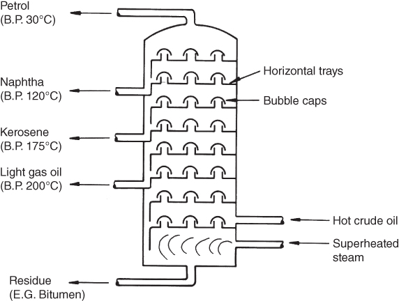
Figure 7.7 Schematic of a fractionating column.
Continuing with the example of the naphthas, the fractions can then be ‘cracked’ to produce the gases ethylene and propylene. ‘Cracking’ is the name given to the process of breaking down larger molecules into smaller ones. This is usually done with the assistance of a catalyst to accelerate the process. The ethylene is then polymerised to form polyethylene, the structure of which was shown in Figure 6.6b, or PVC, polyester or synthetic rubber. The propylene is polymerised to produce polypropylene, which is the basis for polyurethane, acrylic fibres, nylon and some foam plastics. Chemicals other than the naphthas are also used to produce plastics, for example, toluene is used to produce benzene that can be further processed to give a range of useful plastics.
Ethylene is also used to produce styrene, which polymerises to produce polystyrene. Figure 7.8 shows schematically the production of polystyrene; this serves as a typical example of the plastic production process. A partial polymerisation by mixing the styrene with a catalyst in tanks begins the process. The valves to the preliminary mixing tanks can be opened and closed as necessary to maintain a continuous feed to the reactor. It is in the reactor that full polymerisation takes place, the temperature of this heat generating process is closely controlled. By the time the material reaches the base of the reactor it is a hot liquid plastic at around 200°C. It then passes into a screw extruder that forces the material through a water cooled die. As it emerges from the die the cooled solid plastic is cut up into pellets. As polystyrene is a thermoplastic the pellets will be re‐melted when subsequently used in one of the component moulding or forming processes.

Figure 7.8 Manufacture of polystyrene.
Review Questions
- 1 What are the main ingredients necessary to produce pig iron?
- 2 Briefly describe the process of pig iron production (no sketches are necessary).
- 3 Describe one modern method of steel production.
- 4 What is an ‘integrated’ steel plant and what advantages are to be gained from the integration?
- 5 What is ‘blister’ copper and how is it obtained?
- 6 Discuss why large scale aluminium production first started in areas where cheap electricity was available.
- 7 Sketch five different types of standard material form.
- 8 Natural rubbers are vulcanised during their manufacturing process; briefly state what vulcanisation is and why it is necessary.
- 9 What is the major source of the world's plastics and synthetic rubbers?
- 10 What is the purpose of a ‘fractionating column’ and how does it work?
- 11 Briefly describe how polystyrene is produced.