
21
Machine Vision
Machine vision systems are found in a wide range of applications within industry and they are an important element wherever automation is implemented. This chapter considers the application and operation of machine vision within manufacturing.
21.1 Areas of Application of Artificial Vision
21.1.1 Qualitative and Quantitative Inspection
This large area of application of vision system has many subdivisions. It is an attractive area for investment as, without the use of automation, visual inspection can account for around 10% of the total labour costs of manufactured products. Qualitative inspection involves using the vision system for checking a product on an accept or reject basis by examining its attributes. For example, a flaw in a glass bottle, a crack in a casting or a discoloured fruit on a conveyor would be attributes that would cause these items to be rejected. Other aspects of this would be the detection of foreign bodies such as mice or insects on a conveyor in a food processing plant, verification of a completed task in an assembly sequence or checking the degree of swarf build up on a drill bit. Quantitative inspection involves using the system to measure the dimensional features of a product or component. Examples of this are measuring the width of steel strip coming from a steel mill, gauging the diameter of a shaft during or after turning or inspecting a completed component dimensionally.
21.1.2 Identification
Rather than check an attribute or measure a feature, the system is used here to identify and classify components or products. The vision process may involve identifying an individual item in a bin of jumbled components, reading characters from a label on a component travelling along a conveyor belt or identifying a component by its shape and other characteristics among other components in a scene. Following on from the identification of a part, the vision system may use this information as an input to a subsequent system, such as a robot, to allow the parts to be sorted and manipulated for machine loading, assembly or routing to a store (see Figure 21.1).
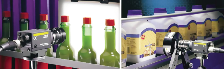
Figure 21.1 Vision systems checking bottle fill levels and label integrity.
Source: Images courtesy of Omron Industrial Automation.
21.1.3 Providing Information for Decision Making, Guidance and Control
The visual data is used in this case to help the robot or automated system decide what to do next in the current situation. For example, laser vision is used in seam tracking in arc welding, here the visual data give immediate guidance to the robot controller to direct the welding torch thus enabling optimum quality welds. In more sophisticated applications, vision can be used in conjunction with artificial intelligence techniques to determine the assembly order of components, or to enable a mobile robot or automated guided vehicle (AGV) to find its way through an unstructured environment.
21.2 Vision System Components
A complete manufacturing automation machine vision system normally requires six different elements, some of which may be integrated into a single unit:
- Camera
- Camera interface and initial image processing equipment
- Frame store or Field Programmable Gate Array (FPGA)
- Control processor (note that elements 2, 3 and 4 may be physically integrated)
- Appropriate scene illumination
- Interfacing equipment to link the vision system to the external world, for example, to provide information to a quality control system, or to an industrial robot or other manipulating system to take appropriate action depending on the image analysis
The relationship between these elements is shown in Figure 21.2 for an integrated vision and industrial robot system.

Figure 21.2 Basic elements of a vision–industrial robot system.
The system elements are integrated in the following manner. First, the camera contains the imaging sensor comprised of thousands or millions of light sensitive photocells. The light from the illuminated scene is focused onto the sensor within the camera. This sensor then produces a voltage signal for each photocell that varies proportionately to the light intensity falling on each one. The signals are transferred to the initial processing stage where they are transformed into a format suitable for further processing. As the data are being handled at a very high rate at this stage it is often necessary to use a storage device to hold the data before further analysis. This is carried out by the frame or picture store or within a FPGA. At this stage a monitor can be used to view the scene observed by the camera. From here the scene is transferred to the system control processor for analysis. The vision control terminal can be used at this stage for setting the various parameters required. To enable a physical reaction based on the information obtained by this system the vision system needs to be linked to, for example, the control computer for the robot. This is done through an interface that can handle the communication between the vision system controller and the robot controller. Thus the basic process is: (i) acquire the image by means of the camera; (ii) process this image into a format suitable for further analysis; (iii) analyse the image to be able to determine for example the identity and orientation of the articles viewed and (iv) make a decision based on this information. To provide further detail, some of the vision system components are now examined more closely.
21.2.1 The Camera
Cameras can be area array or line‐scan, see Figure 21.3. The area array cameras have photocells in the form of a two‐dimensional matrix, whereas the line‐scan camera has a sensor comprised of a single line of a large number of photocells. At the time of writing a typical industrial vision camera area array may have a matrix of around 2000 × 2000 photocell although they can be much higher than this. Similarly, in the line‐scan camera there can be up to 12 000 photocells but since high resolutions lower the line‐scan rate, a resolution of around 3000 may be more typical. The line‐scan camera is used to capture data from very fast moving objects that may be travelling many metres per second.
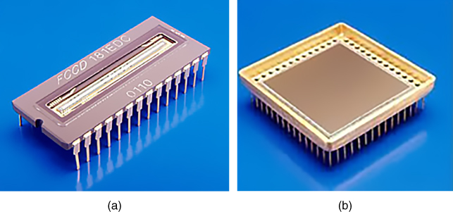
Figure 21.3 Machine vision photocell arrays. (a) Linear photocell array of 2592 × 1 CCD elements 10 μm × 10 μm size × 10 μm pitch. (b) Area photocell array of 2028 × 2048 CCD elements 15 μm × 15 μm in size.
Two main types of sensor are the CCD (charge coupled device) and CMOS (complementary metal‐oxide semiconductor). CCD sensors and cameras produce good quality images and are used in applications such as astronomy, low‐light and low contrast imaging and surveillance and military imaging. However, CCD cameras can suffer from ‘blooming’, this occurs when a very bright area in the scene saturates the relevant cells in the sensor and activates their surrounding cells so that the bright area tends to spread or ‘bloom’. CMOS sensors approach a comparable level of performance as CCD and have a much lower cost since standard manufacturing processes can be used for fabrication. Since CMOS sensors also have lower power consumption than CCD sensors they are popular in industrial vision systems, mobile phone cameras, tablet cameras and professional and amateur photography cameras. In area array cameras, CCD sensors are good for grabbing single images of fast moving objects with no distortion as they usually have what is called a global shutter operation, whereas CMOS cameras, although they can have a faster frame rate than CCD, generally have a rolling shutter effect that can create distortions in the fast moving image due to the manner in which the sensor pixels are scanned.
21.2.2 Camera Interfacing and Initial Processing
The next stage in the vision system requires that the video signal from the camera be converted into a form suitable for manipulation by a computer. For this stage there has been dedicated hardware designed that enables the necessary fast processing times to be achieved. Speed is essential as in the factory environment production must be able to continue at optimum rate unimpeded by the processing time of the vision system.
The light falling on each pixel produces an analogue voltage proportional to the light intensity falling on it. Thus the first stage of the process is called quantisation and it involves examining the light intensity at each pixel and allocating it to a specific grey level, in effect digitising the analogue signal proportional to the light intensity at that pixel. This is possible by creating a grey scale with, say, a value of 0 relating to black, 255 relating to white and the shades of grey in between being allocated an appropriate value. Thus, 8 bits of information will be required to define the brightness of each pixel in a 256 level grey scale. To reduce the processing time and complexity, it is possible to reduce the number of levels or shades of grey down to 128 or 64. Taking this principle to the limit, the scene can be reduced to a binary image, that is, black or white, by representing all grey values above a specified level as white and all below this level as black. Only one bit of information is then needed to register the light intensity at each pixel, although much more attention needs to be given to lighting to enable a high enough contrast between background and object to be obtained.
In grey scale vision, therefore, a very comprehensive picture of a scene can be built up. This means that a great deal of information needs to be subsequently processed to be able to analyse the scene adequately. For example, to be able to extract from the picture the edges of a component from a cluttered background, a comparison of various contrast changes over the whole scene has to be done. This is possible by comparing the grey levels of each pixel with those above, below and on either side.
The binary vision technique is much simpler, faster and usually cheaper, although for it to work reliably the objects to be viewed must be in relatively sharp contrast to their background and preferably not be overlapping or tangled in each other. The binary image is obtained by using a technique called ‘thresholding’ that operates as follows. The objects viewed by the camera are reduced to their silhouettes by setting all the light intensities in the scene background to black and all the object light intensities to white. This could, of course, be reversed depending on whether it was, for example, bright steel objects being viewed on a dull surface or objects placed on top of a light‐table thus showing up as black on a white background. The threshold value is now set by the vision system operator, see Figure 21.4 This value determines which intensities should be set to white and which to black during silhouette formation. The picture is now available in a digitised form, either in grey scale or binary and at a certain resolution.

Figure 21.4 Setting a threshold value.
Although the discussion here used binary and grey scale vision as examples, colour vision is widely used. This is particularly the case in the food industry where fruit may be being inspected for ripeness and quality as it passes along a conveyor belt, to check the colour of baked cakes or to read labels and check fill levels in a bottling plant. Three‐dimensional vision may also be used in some applications where depth information is important.
21.2.3 The Picture (or Frame) Store or FPGA
The frame store is a facility to allow the picture obtained at the previous stage to be held awaiting further processing by the computer. This is not always necessary but is usually part of the system due to the extremely high information transmission rate from the video processor. The computer has to handle large amounts of these data and cannot always operate at a compatible speed with the video, the frame store therefore acts as a buffer between initial picture processing and analysis.
21.2.4 The Vision System Processor
The information now coming to the computer is in a digitised form suitable for further analysis. The first task is to extract or ‘trace’ the profile or edge of the object from the scene. In some vision systems this can be implemented by dedicated hardware and may in fact be part of the pre‐processing stage. In binary vision this edge extraction is carried out by systematically scanning the digitised image for the edges, probably starting at the top left and moving left to right down the frame. A change in signal governed by the threshold limit previously set will signify a change from either background to object or object to background. When the computer recognises one of these edge points it checks the neighbouring points on the line above. This is how it builds up a picture and determines if it is the start of a new component or a continuation of an already scanned one. When the frame scan is fully complete the computer has an ‘image’ of the edges of the object and features such as holes in its memory.
In grey scale vision the principle is similar but many more computations are required. This is because in grey level vision it is not an absolute value determined by the threshold limit that delineates an edge point. Here edges of objects are found by looking for a sharp rate of change of contrast. This means that each pixel point is examined in relation to perhaps four or eight of its neighbours before a value can be attached to it. This examination can be complex for the system may be used, for example, to find small flaws in a casting or for picking individual objects out from a jumbled heap.
Once the image has been stored in the computer memory analysis of the data can begin. A common approach is to examine the object and compare this image with ‘templates’ or ‘models’ held on file. These reference models will have to be taught to the vision system by showing samples to the camera and programming the computer to remember them by measuring and recording various attributes. Thus when the vision system examines a scene later it can compare the attributes of the component it views with those of the component held on file. It can then, depending upon the system being used, recognise components, perceive deviations from the standard models such as flaws, identify the location and orientation of components within the scene or carry out measurement of the object.
Consider, then, that the vision system now has in its memory a record of the scene in the form of an area array of pixels. For this discussion, it is assumed for simplicity that it is a binary system and therefore each pixel is represented by a ‘0’ or a ‘1’ in each memory location. The system can then assess the attributes of the scene or components in view. The following parameters are examples of some of these attributes and how the vision computer can recognise them.
- Area. When it is considered that the binary image is made up of black and white pixels with, say, white pixels representing the object, then the sum of the number of white pixels in the image is a measure of the area of the object. This operation can be carried out by the processor as the image is being scanned thus giving the area measurement immediately the scan is complete. Should a specific measurement, rather than a relative value, be required then the actual size and spacing of the pixels together with lens magnification and object distance would have to be considered.
- Perimeter. This operation can again be carried out as the picture scan proceeds. Where each scan line changes from black to white or white to black this is an indication of the component edge. By totalling the number of changes an indication of the perimeter length is achieved. The changes that occur due to holes within the object can be eliminated by software if necessary. If a measurement of the perimeter is required then once more pixel pitch and so on must be taken into account.
- Perimeter squared/area. This is an indication of the compactness of the object. This feature does not change as the magnification or the scale of the image changes.
- Centroid. The centroid is the position of the centre of area of the object. It is the position given when the first moment of area about both the x‐ and y‐axes is calculated and then divided by the object area thus giving the x and y coordinates of the centre of area.
- Number of holes. If the binary image is being considered as consisting of a black object on a white background, then every white area surrounded by black must be a hole. The number, position and size of these holes can therefore be calculated, stored and used for identification or inspection purposes.
- Maximum and minimum radii. These are the maximum and minimum distances from the centroid to the farthest and nearest points on the perimeter.
- Minimum enclosing rectangle. This is obtained by observing the maximum and minimum points on the x‐ and y‐axes of the perimeter of the object.
The relationship of some of these parameters can also be used to determine the orientation of the component. For example, the angular relationship of the maximum radius to the x‐axis at a point about the centroid can be used, as can the relationship of radius vectors from the centroid to the centres of any holes in the object. Thus, the very asymmetry that necessitates the additional work of orienting the object is used to provide data that can be used to determine its existing orientation.
Figure 21.5 illustrates a rectangular component and some of the attributes mentioned here; the image on the right should be considered a binary one with the rectangle as white and the background as black.
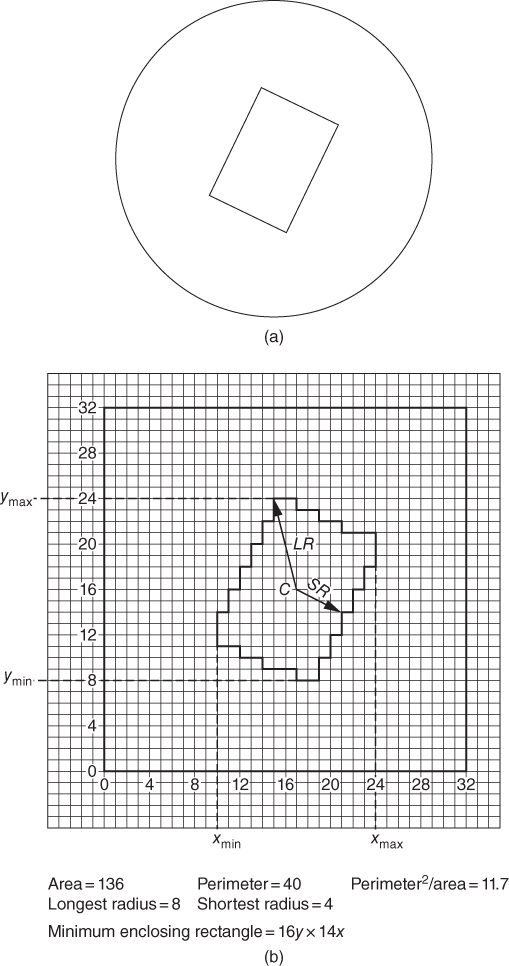
Figure 21.5 (a) A rectangle in the field of view of a very low resolution (32 × 32 area array) vision system. (b) The image as it appears to the system in a digital form.
21.3 Lighting
It is lighting that gives the scene the necessary contrast to enable the component, or component elements, to be differentiated from the background and care has to be taken in selecting the type and arrangement of the lighting system. In binary vision, this requires that the background and object transmit to the vision sensor suitably different light intensity values, for example, the background a white conveyor or illuminated table on which the object shows up as a silhouette or the background could be a matt black surface on which metallic components rest and reflect back to the sensor relatively high light levels. This would certainly be a very artificial situation in many factories where dust and grime are often present covering component and table or conveyor indiscriminately. This is where grey scale and colour imaging can be advantageous as the varying contrast or colour between surfaces can be used to derive the information required to determine the edges or other features of the component. Under the proper lighting conditions it can be used to identify flaws such as scratches and cracks in plastic goods or metal castings. Whatever lighting is used it should be strong enough to prevent interference by ambient light levels surrounding the work area.
Generally, as in photography, manipulation and organisation of light sources can be used to emphasise or reduce shades and highlights. This will facilitate identification of critical features such as component edges or flaws. The use of filtering may also be applied to create contrast between components and background. This may be done by, for example, using a red filter on the lens to enhance red components on a dark background. An example of circular lighting that can be used to provide an even and shadowless image is shown below in Figure 21.6.

Figure 21.6 (a) Light rings and (b) light rings in application.
Source: Images courtesy of Keyence UK Ltd.
21.4 Some Further Application Examples
Figure 21.7 shows how a monotone system can be used to detect flaws in bricks in a robotic brick palletising application.
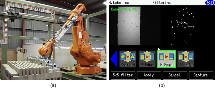
Figure 21.7 (a) An industrial robot is shown palletising bricks with a vision system inspecting the bricks before stacking. (b) The image from the programmer's monitor; the grey scale image shows a crack in a brick and the binary image shows how this vision system perceives this as a series of pixels forming a recognisable crack pattern.
In Figure 21.8, a colour vision system is being used to check the quality of fruit on a conveyor system.
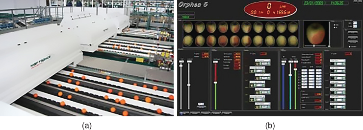
Figure 21.8 (a) A fruit conveyor system is shown with a vision system inspecting the fruit before packing. (b) The image from the programmer's monitor. The images will be in colour on the screen and show the quality of the fruit passing along the conveyors. This is monitored by the system that decides automatically whether or not the fruit is damaged or over ripe depending on the colour. Flawed fruit can then be ejected before packing.
21.5 Conclusion
Automation has many facets and components that cannot be addressed in the space available in this text, however, the essentials have been presented here in a form that should convey both the context of manufacturing automation and useful examples of components and applications.
Review Questions
- 1 Discuss fully three areas of application for machine vision in industry.
- 2 What are the basic components of a machine vision system?
- 3 Within a vision system the sensor photocells may be arranged in a linear array or area array configuration, briefly note typical applications of each.
- 4 The sensor used in the machine vision system may be CMOS or CCD, briefly describe the differences between them.
- 5 Describe a typical sequence of operations that occurs within a vision system in order for it to recognise a component and to determine if that component has a flaw.
- 6 Why is the choice of lighting important for machine vision systems?