
13
Additive Manufacturing Processes
13.1 Introduction
Compared to some of the other processes noted here, additive manufacturing is very new. For example, a casting of a copper frog has been found that was probably made around 5000 years ago, whereas additive manufacturing only appeared commercially around the late 1980s with the introduction of stereolithography. The reason for the late appearance is that the process was only possible due to the confluence of microprocessor‐based technologies, lasers, high precision manufacturing and the ability to directly interface with computer aided design (CAD) systems that led to ‘direct digital manufacturing’ being a term used to describe the process.
Additive manufacturing equipment takes its fabrication information from a CAD model. This model may be created by practitioners from any number of disciplines such as product design engineers in the aerospace and automotive industries, architects, artists, industrial designers, sculptors, surgeons, dentists or by individual hobbyists using domestic additive manufacturing equipment. The CAD model should be volumetric, that is, a solid model, thus providing full three‐dimensional data for the finished object. The data in the model is generated in such a manner that a large number of horizontal slices through the model can be created. Each slice contains the data required for the additive manufacturing equipment to lay down or cut through one layer of fabrication material. The height of these slices contributes to the vertical resolution of the finished fabrication. The file format for this operation should ideally allow dimensions, colours, textures and materials to be represented.
13.2 Advantages of Additive Manufacturing
- Components can be produced directly from CAD models with no intermediate work, such as the creation of an expensive mould for a casting process. This greatly reduces the lead time for prototyping and also provides the opportunity for producing individualised products for the consumer or even allowing the consumer to produce their own products or replacement components at home using desktop equipment.
- There are few restrictions on design. Finished complex components can be made in polymers, metals or ceramics that would be difficult or impossible to make in a single operation by machining or any other process.
- Physical models can be made directly from 3D laser scanning of other objects, for example in reverse engineering, or in medicine directly from CT and MRI scans to allow better decision making before surgery. Examples of applications are included at the end of this chapter.
13.3 Disadvantages of Additive Manufacturing
- It is not economical for large production volumes as only one or a small number of parts can be produced in each cycle and the cycle time is slow.
- In current commercial systems the resolution and surface finish is relatively low compared to, for example, precision machining. Research is continuing to improve this and in the meantime post manufacture finishing treatments such as additional machining and polishing can ameliorate the problem.
- The range of materials available for additive manufacturing is relatively limited to traditional manufacturing processes, although as the technology improves this range is becoming wider.
13.4 General Types
There are a number of ways of classifying additive manufacturing technologies. At the time of writing one important and established method is that of the International Organisation for Standardisation (ISO) and the American Society for Testing and Materials (ASTM). This can be found under ISO/ASTM52900‐15: Standard Terminology for Additive Manufacturing – General Principles – Terminology. It is divided into Binder Jetting, Directed Energy Deposition, Material Extrusion, Material Jetting, Powder Bed Fusion, Sheet Lamination and Vat Polymerisation. Figure 13.1 below shows these and under each is an example of a process that represents the particular technology. The following sections then briefly explain the processes.
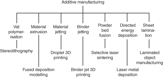
Figure 13.1 Principal additive manufacturing starting materials and examples of processes.
The size of the artefacts created by the processes shown in Figure 13.1 is dependent on the size and configuration of the additive manufacturing equipment. They all could be capable of creating a product of up to one cubic metre, although much smaller sizes are more common, particularly with the liquid and powder bed systems. At the other extreme, much larger items can be created for depositing molten materials, such as in the Fused Deposition Modelling process by using industrial robots or specially designed cartesian machines. Also note that figures relating to layer thickness and resolution or tolerance are approximate as alternative manufacturers or suppliers may offer different specifications. Factors influencing this include the equipment being used, product size and delivery time requested.
13.4.1 Vat Polymerisation – Stereolithography
Stereolithography is a good process for producing models that are to be used for demonstration, prototyping or for ergonomic analysis as they do not require very good mechanical properties. However, it is excellent for producing small intricate parts with fine detail.
In this process, a viscous photosensitive polymer resin is selectively cured using a directional laser beam. Materials such as acrylic and epoxy liquid polymers will cure and solidify when exposed to the light of an ultraviolet laser as shown in Figure 13.2. Following a path determined by the CAD model the laser traces out one layer in the x‐y plane of the fabrication, whereupon the build platform moves downward an equivalent distance to the next required horizontal slice and the laser solidifies the next layer. A typical layer thickness is between 0.05 and 0.15 mm. This continues until the fabrication is finished, see Figure 13.3. If any part of the object is temporarily separate from the main body for part of the build, or is otherwise needing support, then additional scaffolding will need to be created during the build process. This will be designed to be easily removed later. Between the laser scan of each layer a recoating wiper blade is drawn across the surface to ensure it is level across the whole work area. When the process is completed the build platform is raised and the resin is drained to allow the fabrication to be removed. The fabrication may be further exposed to UV light if additional curing is required. Finished products are commonly up to 500 × 500 × 500 mm although fabrications over 2 m long can be created. Tolerances for stereolithography in the x–y plane are around ± 0.13 mm for the first 25 mm then ±0.05 mm for every additional 25 mm. Along the z‐axis the tolerance is ±0.25 mm for the first 25 mm then ± for every additional 25 mm.

Figure 13.2 Stereolithography (SL).
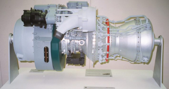
Figure 13.3 This multipart engine model used stereolithography to achieve a detailed prototype.
Source: Image courtesy of Vaupell Rapid Solutions.
Mask Projection Stereolithography reduces the build time of SL artefacts. This is due to replacing the single scanning laser beam with a dynamic mask. This allows an entire cross‐sectional area of the fabrication to be exposed to ultraviolet light at the same time rather than progressively. The mask can be altered instantaneously for each layer by the use of a digital micromirror device (DMD). This type of mirror is composed of hundreds of thousands of microscopic mirrors each of only around 13 μm square arranged in a rectangular array. Each of the mirrors can be electronically switched in microseconds to an ‘on’ or ‘off’ position thus creating a dynamic mask where each mirror may be considered as one ‘pixel’. Layer thicknesses and fabrication size is the same as for laser scanning stereolithography.
The materials used in stereolithography are not thermoplastics but they rather mimic thermoplastic properties. One of the results of this is that if they are exposed to moisture and ultraviolet light in service for long periods they suffer degradation in a change in mechanical properties and appearance. Although they can be protected by painting or plating they are not usually intended for long term use.
13.4.2 Material Extrusion – Fused Deposition Modelling (FDM)
In Fused Deposition Modelling (FDM) a thin filament of a thermoplastic polymer such as ABS or a polycarbonate is initially extruded onto the build platform then progressively added to in order to form the finished fabrication. Wax could also be used in order to create patterns for investment casting. In Figure 13.4 the extrusion assembly moves in the x–y plane depositing the filament in a layer corresponding to a horizontal slice from the CAD program. The build platform may move down or the extrusion assembly move up the necessary distance for the next layer to be deposited.

Figure 13.4 Fused deposition modelling (FDM).
Other configurations of the extrusion system are possible, for example, instead of one that is cartesian, a six‐axis industrial robot may be used to hold the extrusion nozzle. The extruded material, heated to just 0.5°C above its melting point, is at such a temperature that it fuses seamlessly by cold welding to the previously deposited material. Thus as each subsequent layer is added the finished fabrication takes shape. An additional filament and nozzle supplying easily removed support or scaffolding material may also be used when aspects of the fabrication are fragile. Since the movement along the x‐, y‐ and z‐axes is mechanical it is slower than those systems that use a laser in the fabrication process. However, it is very popular and FDM equipment is widely available from high end industrial systems to those that can be used by hobbyists at home. An example part is shown in Figure 13.5.

Figure 13.5 A component produced by FDM that would be difficult to make in one operation by conventional manufacturing methods.
Source: © 2018 Stratasys Ltd.
Parts with very good strength to weight ratios, and thermal and chemical resistance can be created. Also complex shapes both externally and internally can be created that would be difficult, expensive or impossible to achieve with traditional processes. Typical layer thicknesses could be between 0.1 and 0.5 mm with tolerances of around ±0.1 mm depending on size. Part size is determined by the configuration of the extrusion system that could be a gantry type or an industrial robot. The largest machines can produce artefacts of many cubic metres but these are very unusual. A machine capable of 1 cubic metre would normally be classed as large and most machines will be producing much smaller parts.
13.4.3 Material Jetting – Droplet 3D Printing
Material Jetting – Droplet 3D Printing equipment utilises a cartesian configuration in which a printer head moves in an x–y plane over a build platform in a manner similar to an inkjet printer. The build platform will move down in the z‐axis a distance of one layer after each horizontal slice is completed. A number of printer nozzles mounted on the gantry allow droplets of different materials and colours to be combined in‐process. The molten droplets are deposited on the build table then onto the previously deposited layers until the artefact is completed. The droplets are instantly cured and solidified by ultraviolet light as they seamlessly weld to those that are already laid. After completion the post processing will include removal of any support structures created. Examples of artefacts are shown in Figure 13.6.
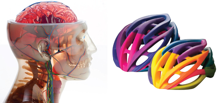
Figure 13.6 A Medical model and bicycle helmets produced by droplet 3D printing.
Source: © 2018 Stratasys Ltd.
The process is capable of producing a wide range of attractive and useful models but only in photopolymers. Depending on the polymers used the finished artefact can be hard and rigid, soft and flexible, transparent or opaque. Layer thickness can be as small as 0.013 mm, it is relatively precise and a wide variety of photopolymers in different colours can be used.
13.4.4 Binder Jetting – Binder Jet 3D Printing
Binder Jetting – Binder Jet 3D Printing is a powder bed process so called because a printer head operating in the x–y plane, similar to that in an inkjet printer, ejects adhesive bonding material in the form of droplets onto a layer of powder in the powder bed. This powder may be of a number of materials including metals or ceramics. The powder is held in a chamber under the printer head. As one layer corresponding to one horizontal slice of the CAD model is completed the build platform drops by a distance equivalent to the next layer. Additional powder is then added and the process is completed. Layer thicknesses are between 0.1 and 0.2 mm. The bonded material forms the completed part and the loose powder acts as a support and can be readily removed when the fabrication is completed. When metal powder is used the finished artefacts can be put into an oven to fuse the powder grains together, thus producing a product with similar characteristics to one that is sintered. Artefact sizes of 1 cubic metre would be regarded as large and smaller sizes are more common, see Figure 13.7.
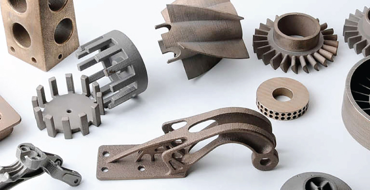
Figure 13.7 Some components produced by binder jet printing.
Source: Image courtesy of ExOne.
13.4.5 Powder Bed Fusion – Selective Laser Sintering
Selective laser sintering (SLS) allows a wider range of materials than the polymers noted in the first two processes. It can be used to create fabrications from powdered metals, ceramics and polymers.
The equipment consists of a powder bed chamber containing the powder from which the artefact is to be made this the powder is supported on the build platform. There will also be one or two chambers containing the supply powder. Although only one supply chamber is shown in Figure 13.8 an additional chamber located to the right of the build chamber can also be present. In this process as the moving laser beam traces out one horizontal slice of the CAD model the powder is fused over the traced cross sectional area. The build platform is then lowered a distance equivalent to the determined layer thickness, which may be between 0.05 and 0.5 mm. Next a powder spreader roller moves across the supply powder and pushes fresh powder across the surface of the powder bed ready for the next scan of the laser. Thus, layer by layer the finished artefact is produced with unfused powder acting as a support where necessary.
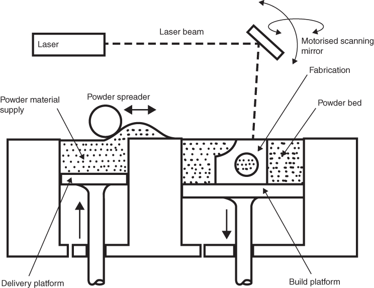
Figure 13.8 Selective laser sintering (SLS).
Where metal powders are used the whole assembly may be contained within a nitrogen filled cabinet in order to prevent oxidation of the build material. When the fabrication is complete the excess powder can be removed and the finished product extracted. Tolerances in the x–y plane are ±0.13 mm for the first 25 mm then and additional ±0.13 mm for each additional 25 mm and in the z‐axis ±0.25 mm for the first 25 mm then an additional ±0.13 mm for every subsequent 25 mm. Maximum sizes would normally be no larger than 1 cubic metre, although it is often smaller. Figure 13.9 parts (a) and (b) show fabrication examples.

Figure 13.9 (a) A physical polymer wire‐frame model created by SLS. (b) A complex metal component created by SLS © Copyright Renishaw plc.
Source: All rights reserved. Image reproduced with the permission of Renishaw.
Source: Image courtesy of CIDEAS Inc. www.buildparts.com.
13.4.6 Directed Energy Deposition – Laser Metal Deposition
Directed Energy Deposition – Laser Metal Deposition uses a powerful laser beam that is focused from a nozzle onto a substrate to create a weld pool. Metal powder or wire is then added simultaneously to the weld pool via the nozzle and through an inert gas such as argon to protect the material from oxidation. The metal solidifies rapidly and the fabrication is then built up by horizontal layer corresponding to the slices generated by the CAD model.
Typically, each layer may be between 0.1 and 1.0 mm, however, the weld bead can range from 0.03 mm for micro manufacturing to over 5 mm for coarser work. The substrate may be mounted on a platform with one or more degrees of freedom and the nozzle could be held in an industrial robot having six degrees of freedom. This means that finished parts of complex geometry can be created in a single operation, see Figure 13.10.

Figure 13.10 A vane produced by laser metal deposition.
Source: Image courtesy of RPM Innovations Inc.
The process can also be used to combine different materials such as in cladding, for example, a lightweight but soft base metal can be clad with a thinner but hard‐wearing metal as the two materials will be seamlessly fused together during the process. A wide range of metals can be used such as titanium, steel, nickel and aluminium. An advantage of the process is that it is possible to control the grain structure and hence the resulting mechanical properties of the artefact. Part sizes normally range from a few centimetres up to any size the manipulation system can provide although normally no more than a metre cubed. At the time of writing, Directed Energy Deposition is still not widespread and research into improving the process is ongoing.
13.4.7 Sheet Lamination – Laminated Object Manufacturing (LOM)
Here, the starting material is in the form of sheet held on a supply roll as shown in Figure 13.11. The material is unwound and indexed over a platform between support rollers before being wound onto a take‐up roll. The sheet material may be paper, cardboard, plastic or metal foil. At each indexed step a laser is used to cut out a profile equivalent to the corresponding horizontal slice from the CAD model. The laser is set such that it will only cut through one layer of the material at each step. The laser also crosshatches the excess material to enable easy removal of the fabrication. The laser may be directed by a mirror system or the whole laser assembly may move in the x–y plane. Alternatively, a sharp blade can be used to cut the material. After each cut the platform is lowered by the thickness of the sheet material. Each layer is fixed to the layer below either by an adhesive backing on the sheet, which can be activated by a heated roller or by adding adhesive between each cutting operation. The height of the fabrication can be monitored in‐process to optimise accuracy. When the process is completed the finished fabrication is removed and can be worked further if necessary. If paper or cardboard has been used the fabrication has the appearance of wood and can be worked as such, however, a sealing operation is necessary to prevent the absorption of water.

Figure 13.11 Principle of laminated object manufacturing (LOM).
Artefacts of 1 cubic metre and above can be created using this method. The vertical resolution is dependent on the sheet and bonding layer thickness and full colour objects can be created directly. However, it is not as accurate as other additive manufacturing process and due to this functional prototypes have not normally been created, nor has it been usual to create parts with complex geometries or internal cavities. As an exception to this recently the use of carbon fibre sheet combined with nylon or other polymers has been used to produce high strength prototypes as shown in Figure 13.12. More common applications include producing patterns for sand casting and, since the materials are inexpensive, relatively low cost conceptual scale models for architects and product designers.
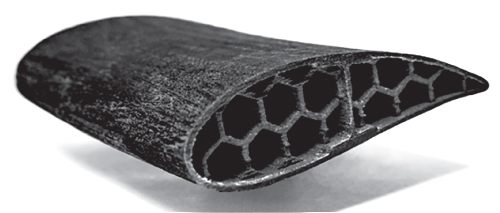
Figure 13.12 Aerofoil section produced from carbon fibre sheets.
Source: Image courtesy of Impossible Objects.
Review Questions
- 1 Discuss three advantages and three disadvantages of additive manufacturing.
- 2 Name seven general categories of additive manufacturing processes.
- 3 With the aid of a rough sketch describe the process of stereolithography and include comments its precision and use.
- 4 With the aid of a rough sketch describe the FDM process and include comments its precision and use.
- 5 With the aid of a rough sketch describe the selective laser sintering (SLS) process and include comments its precision and use.
- 6 With the aid of a rough sketch describe the LOM process and include comments its precision and use.