
28
Human Factors in Manufacturing
28.1 Introduction
Manufacturing is about people just as much as it is about technology and organisation. As well as creating products for people to use, manufacturing involves the use of people in the creation process. Some of the factors that relate to these people are considered in this chapter.
Within the manufacturing system people should be able to enjoy their work and carry it out efficiently in a pleasant, healthy and safe environment. Here, we will examine how these criteria are met by looking at the areas of job satisfaction, health and safety and ergonomics, including the work environment.
28.2 Job Satisfaction
Before people can enjoy their work and gain satisfaction from what they are doing they must feel motivated to carry out that work in the first place. In 1943 Abraham Maslow proposed a ‘Theory of Human Motivation’ that included a hierarchy of needs composed of five levels (see Figure 28.1). He said that needs would appear in ascending order only. For example, a physiological need would be the satisfaction of hunger and thirst, and the need for safety would be of secondary importance until these essentials of life had been acquired. In our industrialised societies with advanced economies the physiological needs are usually satisfied for most members of society. Similarly, on a general level, safety needs are satisfied except in specific cases where, for example, war, accidents or criminal acts might occur. The social needs at level 3 will be satisfied through the personal life of the individual through family, friends and often the workplace. Many people also look to work to help them satisfy the esteem and self actualisation or realisation needs suggested at levels 4 and 5. This work may be that of a parent who works full time at home raising a young family, a volunteer worker with a charity, or someone who is self‐employed and so on. In this chapter, we are mostly concerned with the manufacturing employee working in an engineering environment.
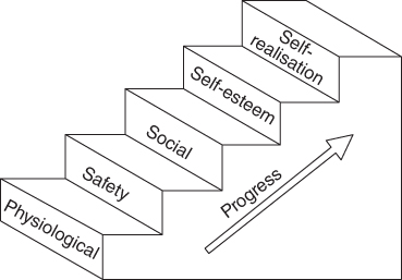
Figure 28.1 The Maslow Scale of the hierarchy of human needs.
In Chapter 24, Work Study was examined as a means of improving the efficiency and ease with which a job could be completed; however, additional factors should also be taken into account when designing a job for a worker. Psychological factors should be considered to ensure that the worker is able to experience fulfilment of levels 4 and 5 on the Maslow scale. It may be argued that in most cases this is unnecessary and that many people will be willing to do a particular job simply for the pay alone. This is all very well, but it should be remembered that it is the best performance we are looking for from a worker, not one that is mediocre or barely adequate.
Factors such as monotony of movements and boredom should be minimised. This appears contrary to the principle of specialisation and division of labour where simple repetitive tasks are used to produce high labour productivity. But, as in everything involving human beings as individuals, there is no perfect solution to any problem. There is evidence that some individuals actually prefer to have a rigidly defined, repetitive work cycle as can be found in, for example, mobile phone assembly, while others benefit from variety and flexibility in how they are allowed to tackle a job. The traditional way to assemble mass produced items such as motor cars is to use an assembly line. Here, the manual workers have to work at the same speed as associated machinery and at a rate governed by the speed of, say, a conveyor belt. In this case, each worker completes a simple operation and repeats this many hundreds or thousands of times per day. Monotony, boredom and fatigue can occur in these situations and this leads to poor quality products, absenteeism and high labour turnover rates. It has been found that by changing the job so that the individual workers can each build a larger part of the finished product and in the extreme case a complete car, then work satisfaction can improve. This leads to a greater pride in the job and better quality. Absenteeism and labour turnover also reduces and this lowers the costs involved in lost time and in training new workers. Naturally, the actual production rates will be slower as the benefits of labour specialisation are lost; this loss in production rate generally is so important that almost all mass production factories today still adhere to the production line system, though the needs of the individual will still be recognised and satisfied where possible.
Job satisfaction is therefore obtained by meeting a number of needs for the individual worker. As each combination of worker and manufacturing situation is unique, so the solution to the job satisfaction problem will be unique. In the ideal situation, individuals will be chosen to suit jobs and jobs designed to suit individuals. However, as the ideal situation seldom occurs, a ‘best compromise’ will probably be the only solution.
28.3 Health and Safety
As explained in the previous section people need and expect to be able to work in a healthy and safe environment. As also explained, where people are involved perfection is not possible. A human trait is that we make occasional mistakes; under the wrong circumstances these mistakes can cause accidents of varying degrees of seriousness. The mistakes may be made by an engineer at the design stage of a product, there may be a mistake made by someone preparing a procedure to be followed in operating a process plant, or someone may make a simple mistake such as pushing the wrong button or carelessly walking too near moving machinery. Each of these mistakes could cause an accident and it is estimated that hundreds of people are injured or killed every day throughout the world due to industrial accidents alone. Another aspect that must be considered is the health of the individual within the manufacturing system. Again due to human error and commercial pressure, conditions detrimental to health may appear. In this section, we will look at the provisions that should be made to make work both healthy and safe.
28.3.1 Legislation and Risk Assessment
In most countries today, laws exist to provide a minimum standard of health and safety within industry. For example, in the UK there is the Factories Act and the Health and Safety at Work (etc.) Act. There are also further Regulations and Codes of Practice approved from time to time to suit new and changing situations, for example, COSHH (Control of Substances Hazardous to Health Regulations). Copies of extracts of these publications, relevant to the particular industry concerned, must be displayed in prominent positions in work areas. This ensures that all employees have access to a general knowledge of the law as it relates to their own situation. Adherence to the law is ensured through inspection visits by the Health and Safety Executive in the UK. It is an offence to obstruct an inspector during the course of his duties and he has the power to inspect a factory at any time of the day or night. Each country has its own system of law but the broad scope and content of regulations are, by necessity, very similar. We are concerned here with manufacturing industry and the subject will be considered under the headings of health, safety and welfare.
Risk assessment by law must be carried out in all situations where people are present or likely to be affected by an activity or product, for example, teachers and pupils in education, patients and medical staff in hospitals and crew on marine craft. Risk assessment should also carried out by those designing systems such as aircraft, motor cars, buildings, research experiments, software for financial products and so on. In our case we will focus on the working environment in a manufacturing facility.
A risk assessment ensures identification and careful consideration of factors in the workplace that could cause harm. It also facilitates this by the use of a step by step procedure that is written down to ensure the analysis is logical and thorough. This also provides a record for the future should an accident occur and acts as evidence of what was considered and also provides a basis for creating and implementing improvements.
First, hazards, which are qualitative and risks, which are quantitative, must be identified.
A hazard is anything that can cause harm, such as the presence of electricity, radiation, wet floors, working from a height and so on.
A risk is the likelihood that a person could be harmed by a specific hazard. It can be allocated a value such as high, medium or low. If statistical or historical data are available then a specific value in terms of a percentage can be allocated. Additionally, the severity of the risk should be considered. As a first step in the assessment categorising the levels of risk severity is necessary in order to decide on what action will subsequently be appropriate for reducing risk. This can be done in the form of a table as shown in Table 28.1.
Table 28.1 Categorising levels of risk severity.
| Severity or consequences of harm | |||||||
| Risk matrix Likelihood of harm | Insignificant, e.g. requires basic first aid | Minor, e.g. deep bruise | Moderate, e.g. deep cut, torn ligament | Severe, e.g. fracture | Extremely severe, e.g. permanent disability, death | ||
| Rare: <1 in 1000 chance | Very low minor risk | Very low minor risk | Very low minor risk | Low moderate risk | Low moderate risk | ||
| Unlikely: 1 in 200 chance | Very low minor risk | Very low minor risk | Low moderate risk | Medium significant risk | Medium significant risk | ||
| Moderate: 1 in 50 chance | Very low minor risk | Low moderate risk | Medium significant risk | High severe risk | High severe risk | ||
| Likely: 1 in 10 chance | Low moderate risk | Low moderate risk | Medium significant risk | High severe risk | High severe risk | ||
| Probable: >1 in 3 chance | Low moderate risk | Medium significant risk | High severe risk | High severe risk | High severe risk | ||
| Severity of risk | Action to be taken | ||||||
| Very low, minor risk | Implement practical short term control measures | ||||||
| Low, moderate risk | Attention indicated | ||||||
| Medium, significant risk | Corrective action needed short term | ||||||
| High, severe risk | Discontinue operation and/or immediate action | ||||||
The UK Health and safety Executive suggests the following five steps.
- Identify the hazards
- Decide who might be harmed and how
- Evaluate the risks and decide on precautions
- Record significant findings
- Review the assessment and update if necessary
The next step is to create an action plan using a form similar to the one shown in Table 28.2. The table would be extended downward until all of the hazards had been identified and listed.
Table 28.2 Listing of hazards, those at risk, risk level, action plan and result.
| Activity: Lifting metal blank and inserting into press | Location | |||
| Hazards List anything that could cause harm | Who is at risk List those exposed to hazard | Risk Decide on level of risk for each hazard | Control measures/Action plan List measures to be taken to minimise risk | Revised risk after implementing control measures |
| Lifting metal blank: back strain; cut to hands | Press operator |
Low Moderate risk |
Provide lifting training. Provide safety gloves Ensure work at proper height | Very low minor risk |
| Inserting metal blank into press: loss of fingers or complete hand | Press operator |
High Severe risk |
Provide appropriate training and press guards. Ensure press will not operate unless operator's hands are clear (two hands needed to activate press) | Very low minor risk |
28.3.2 Health
Within the factory the working conditions should be such that no hazard to health exists. There should be no fumes or particles in the atmosphere that could cause harm in the short or long term. If such particles do exist, then protective clothing and breathing equipment or filters should be provided and worn. For example, particles of fibreglass or asbestos are particularly dangerous and the best way of dealing with this type of hazard is to remove it at source. Substitute materials should be found, or an alternative process that does not produce these particles or effective filters at the point of particle creation should be used. Grinding operations, handling sacks of powder material such as flour and paint spraying are all tasks that involve the possibility of inhaling harmful material. A method of removing the human element in these jobs is to automate them using industrial robots and this is in fact common practice, with large productivity gains being experienced, particularly in paint spraying applications.
More general considerations include the following. There should be a high standard of cleanliness in factories and this applies not only to foodstuff and electronics manufacturing. The floors, walls and ceilings should be regularly cleaned, washed and redecorated at reasonable intervals. Refuse bins and other rubbish should be cleared daily; this improves hygiene and also reduces the risk of fire. Workers themselves should also ensure their clothing is kept clean as very serious skin disorders can occur due to prolonged contact with oily clothes. There should be no overcrowding and around 12 m3 per person should be regarded as a minimum, though this will obviously increase greatly if material handling is required and large machines are present. Food should also not be consumed where there is a possibility of absorbing poisonous fumes or dust.
Lighting must be adequate in every part of the factory to prevent accidents and avoid eye fatigue. Noise levels should be kept to a minimum and adequate hearing protection worn where necessary. Work areas should be well ventilated. Suitable temperatures should be maintained and the heating methods used should not in themselves be harmful. These factors will be considered again in the section on ergonomics later.
28.3.3 Safety
28.3.3.1 The Cost of Accidents
Within industry about 50% of all accidents are caused by either handling and lifting or machinery. Apart from the personal discomfort and distress experienced by the victim and their family, there is also the financial cost of accidents to be considered. These costs arise due to lost production, loss of earnings of the individual, cost of benefit paid to the worker if injury results and cost of compensation and or legal costs if legal action is taken by the victim in pursuit of a claim. The cost of production time lost may be considerable; this arises due to the lost time of the injured employee; the lost time of other employees who stop work to give assistance or are curious, sympathetic or shocked; the lost time of foremen and managers who have to investigate and report on the accident; the cost of retraining someone to do the injured person's work; the cost of repairing damage that may have resulted to equipment and so on. The loss of earnings to the employee involved in the accident may cause anxiety to himself and his family. This can be offset by compensation payments though these will probably not be immediate and cannot, of course, ever totally compensate for pain and suffering. Thus the cost to government, industry and individuals is considerable and runs into millions of pounds per year.
28.3.3.2 The Causes of Accidents
Accidents occur due to unsafe acts, unsafe conditions or both. The unsafe act might be one of the following; someone operating a machine without authority or proper training; someone disabling a safety device in order to improve their rate of work or working from an unsafe position or adopting an unsafe posture. Examples of unsafe conditions are: inadequate lighting, oil on floor, overcrowded work areas and dangerous work arrangements. These and other unsafe acts and conditions are termed ‘hazards’. They occur everywhere people are present and they eventually cause accidents. Hazards are caused by people: sometimes the human error occurs very early on in a chain of events and the accident is separated widely in time from the unsafe act. An example of this would be a faulty weld on a ship's hull that becomes apparent as an accident only months later when a crack appears and propagates catastrophically. Often there is very little time between the unsafe act and the accident. An example of this would be an operator ducking under a guard rail to get at a piece of equipment and being hit by, say, the moving arm of an industrial robot located behind the rail.
28.3.3.3 The Prevention of Accidents
This can be considered under four areas: the original design of equipment and machinery used, the physical layout of the work area, the training adopted by the factory personnel and the safety devices and procedures in place.
First, equipment and machinery should be designed by qualified engineers and all materials and components to be used clearly and unambiguously specified. Quality components should be incorporated, they should have a minimum of moving parts and be solid state where appropriate. If possible, the type of components used should already have proven their reliability in other applications. The equipment and machinery should be manufactured under well supervised conditions and to specification. Records should be kept of how the work was done, who did it and the result of any inspection operations or tests carried out.
Having ensured that the equipment used has been designed and manufactured to satisfactory safety standards, the next stage is to install the equipment so that it can be operated in a safe manner.
All personnel within a factory or other industrial environment should receive basic safety training. This will inform them of unsafe practices, the need for tidiness and cleanliness and any hazards particularly associated with their work. For example, ‘substances hazardous to health’ have to be carefully controlled regarding their use and storage and all personnel likely to come into contact with them should be made aware of any special precautions to be taken. Those who operate machinery and other equipment must receive specialised training regarding their work. This training is essential if safe working conditions are to prevail. The supplier of the equipment being used could provide the training and should also ensure that the equipment has been installed safely. It may be necessary to compile a ‘safety manual’ to be read by all who are going to operate the equipment. In a particularly dangerous area a ‘permit to work’ might be issued to the relevant personnel and access denied to those with no need to be there.
Hazardous equipment and machinery should be guarded. This can take many forms and some of these are now noted, see also safety for reprogrammable equipment in Chapter 20.
- Fencing. This may vary from a simple handrail about 1 m high, to a complete cage using 2 m high steel mesh or toughened Perspex. The caging would be used in most areas where large pieces of moving machinery are present. The space between the equipment and the fence would be adequate to allow maintenance personnel access. Gates into these work areas should be interlocked into the electrical power to the equipment. This means that if a gate is opened a switch built into the gate automatically switches the equipment off.
- Light curtains. Instead of building a physical barrier it is possible to use light beams. In these systems an array of light emitting diodes (LEDs) passes light across a gap of a few metres to an array of photosensors. When someone passes through the gap, the beam is broken and the equipment is switched off.
- Pressure sensitive mats. These are used either at entrances to work areas or around the hazardous machinery. Should someone step on the mat, a switch is closed, so stopping the equipment. These mats are pneumatically or electrically operated.
- Guards. Guards actually on the machinery are common. These usually open to, allow the machine operator access while the machine is at a safe part of its cycle. They are also interlocked to ensure that the dangerous parts of the machine cannot move until the operator withdraws from the danger area and closes the guard.
- Safety equipment. All workers should wear appropriate safety equipment. In almost all workshops it is necessary to wear protective goggles. These will prevent damage to the eye from flying particles such as may be present during grinding and cutting operations. Because of the harmful radiation given off when electric arc welding, welders must use protective face shields with tinted viewing windows. Protective helmets, or ‘hard hats’, should be worn where there is any overhead working taking place.
- Fire precautions. There are regulations regarding the number and position of fire exits within a building. Exits should be easily accessible, easily opened from the inside and never locked. Personnel should be conversant with the procedure to be followed in case of fire. They should also be aware of the different types of fire extinguisher, what they are used for and their locations, which should be prominent. Flammable materials should be clearly marked and stored carefully; there are special regulations for explosive materials such as pressurised gas.
28.3.4 Welfare
Welfare is an aspect of health and safety in which the more general concerns of the well‐being of the individual are considered. Employers are bound by law to provide adequate facilities for the welfare of their employees. For example, drinking water must be provided in ample quantity and of good quality. Clean drinking vessels or drinking fountains should be available. Clean, well maintained washing facilities should be available and supplied with soap and towels. There should be facilities for the drying and storing of clothes not worn during working hours.
A first aid box should be easily accessible and it should contain an appropriate range of materials for the type of work being undertaken in the local area. The box should be in the charge of a responsible person.
This section has shown that health and safety is everyone's responsibility. The designer, manufacturer and supplier of the equipment to be used in the factory have an obligation to ensure that it is safe to operate and that a clear instruction manual is provided. Employers have to ensure that their premises and procedures conform to the appropriate laws, regulations and codes of practice. They must ensure that adequate training and appropriate safety equipment is provided to the employee. The employee has the responsibility to make be familiar with the hazards that are likely to occur in his job, and to take advantage of any safety training, advice and equipment offered. The next section will consider ergonomic aspects that will combine methods to improve productivity with methods to make work safer and more enjoyable.
28.4 Ergonomics
Ergonomics is the study of the worker's relationship to the surrounding environment with intent to improve efficiency and work satisfaction. It can also be applied to product design to ensure ease of use of the product. The word is composed from the Greek ergon meaning work and ‘economics’. Other terms used for ergonomics are ‘human engineering’ and ‘human factors engineering’. An ergonomist receives and analyses input from both the engineering and the human sciences, for example, materials selection, functional design, statistics, mechanical engineering and so on, and from anatomy, physiology and psychology (see Figure 28.2).
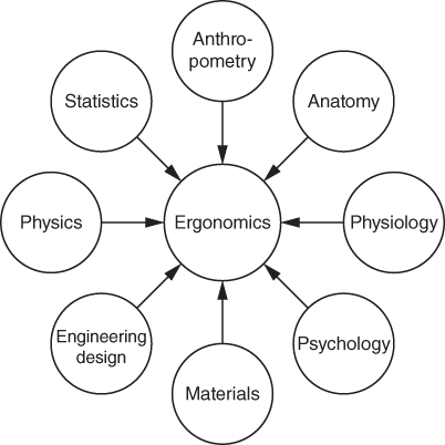
Figure 28.2 Engineering and human sciences contributing to ergonomics.
When a worker is carrying out a job, he is operating in a ‘closed loop’ system. By this we mean that he or she observes a situation, analyses what is happening and what subsequently needs to happen, takes action to cause the required change to occur, observes the result of the action on the situation and so on. This is shown in Figure 28.3. This will occur in any task where a human is actively participating in a process, for example, assembling a product, controlling a chemical plant or even driving a car. All the elements involved in this control loop must perform at their optimum. Here we are concerned with the efficiency of the human operator, how well he or she can observe the situation and how well they can effect the necessary changes. Ergonomics therefore includes consideration of the design of the equipment and workplace, and the general environment surrounding the worker. These two aspects will now be considered in more detail.
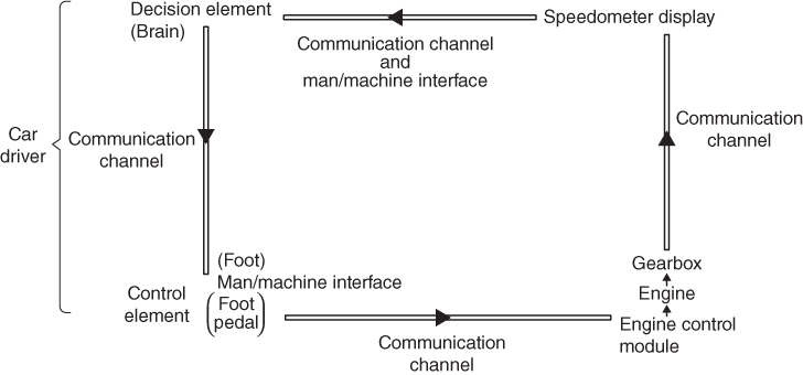
Figure 28.3 Human‐machine closed loop system for car speed control.
28.4.1 Equipment and Workspace Design
All products have to be designed with consideration given to ergonomics. Mobile phones are examples of good ergonomic design and although they often contain excellent cameras there is still a demand for dedicated cameras for the serious amateur and professional photographer. The ‘ergonomically’ designed camera, for example, has its body contoured to fit comfortably into the hand, it is not too heavy, it is balanced for comfortable handling, controls are easily accessible even when looking through the viewfinder and non‐slip surfaces are used where appropriate. In motor cars, gear levers are located for fast and easy shifting, the windscreen is designed for maximum visibility and the fascia panel, containing displays and controls, is easily seen through the non‐slip optimum diameter steering wheel. The principles employed in the design and layout of these consumer products also apply to machine tools, aircraft cockpits and indeed anywhere humans have to interact with products. Some of these principles are now considered.
To ensure that the product design will suit the largest number of people anthropometry, that is, the measurement of people, is used. If a single item is being made, say a made to measure suit or a seat for a racing car, then it can be designed to fit exactly the person that is intending to wear or use it. However, most products must be able to accommodate a range of people, male and female, of varying heights, shapes, strengths and weights, and this is why anthropometry has to be used.
Large amounts of statistical data have been gathered over many years and these are now at the disposal of the product designer. These data are often presented in graphic and tabular form for ease of use. It is usual for a particular characteristic, say the height of the adult male population of the UK, to follow a ‘normal distribution’. A normal distribution is a continuous distribution of some random variable, in this case height, with its mean, median and mode equal. The concept can be seen graphically in Figure 28.4. This symmetrical bell shaped curve represents a normal distribution. It shows that the mean height of the population is approximately 1.7 m. This means that 50% of the population are above and 50% below this height. The ‘standard deviation’ is a numerical factor used to indicate scatter. From the curve it can be seen that one standard deviation from the mean includes about 34% of the population. Two standard deviations above and below the mean enclose about 90% of the population. Thus if a piece of equipment was designed so that people of between 1.6 and 1.9 m tall could use it, then the designer would be confident of his design suiting 90% of the adult male population of the UK.
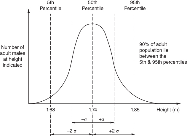
Figure 28.4 Distribution of heights of adult male population.
The anthropometric data can be used to construct models of typical members of the population. These models can be used in graphic computer simulations to assist with design or two‐dimensional cardboard mannikins can be made and Figure 28.5 shows examples of these models alongside the design for a lathe. Figure 28.6 shows a plan view of an operator together with suggested dimensions for a group of adult males using a seated workplace. Seats should be designed to be comfortable and provide proper back support. If the operator is working at a bench doing assembly work then components and tools should be stored at specific locations within easy reach. This will ensure that the operator can develop habitual movements without the need for the eyes to direct the hands.
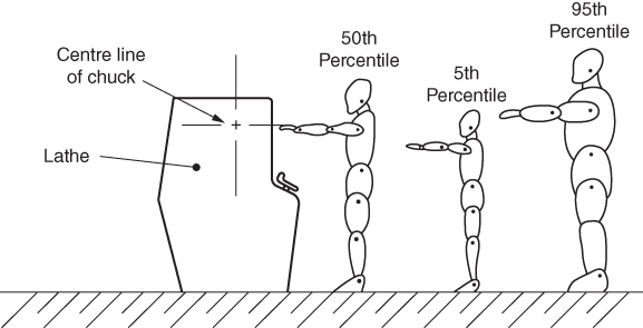
Figure 28.5 Simple 2D models to assist with lathe design.

Figure 28.6 Typical operator dimensions.
As well as considering the dimensions of the equipment and workplace, the designer should consider the instrument displays and control elements that might be used. Displays should convey information to the worker in the simplest manner possible. No unnecessary information should be presented as this could create confusion. This principle is now employed in the pilot's workspace, that is, the cockpit of modern aircraft. Here computer screens display the essential information required by the pilot as the need arises. This reduces the proliferation of confusing dials and indicators that would otherwise be necessary. In the industrial situation the number of displays required is usually much less and conventional displays are the norm. These displays are of three main types, qualitative, quantitative and representational.
28.4.1.1 Qualitative Displays
These are usually visual, but auditory types such as bells, buzzers and sirens can also be used. The distinguishing feature of a qualitative display is that it conveys no numerical information. It is normally employed to convey a warning, for example, red lights to indicate ignition or oil pressure problem in a car and flashing lights on machines that are in operation. Colour coding of these displays should not be regarded as a reliable method of communication as a percentage of the population is colour blind.
28.4.1.2 Quantitative Displays
This type provides numerical information to the user in either analogue or digital form. Everyone is familiar with these two forms through their use on watches and clocks. Examples of these instruments are shown in Figure 28.7. The analogue display shows a reading on a scale analogous to the value it represents; for example, the speedometer on a car. It has the advantage that a quick glance will tell the observer an approximate value for the reading. It is also advantageous in that the rate of change of the variable being monitored is easily seen as the pointer moves over the scale. It has the disadvantage that precise readings are difficult in that if the pointer is between graduations, then an estimate of its true position has to be made. This problem can become worse if the display is read at an angle, as parallax error can occur due to the space between the pointer and the scale. The use of a reflective strip attached to the scale can remove this problem as the observer should line up the indicator with its reflection before noting the reading, see Figure 28.8.
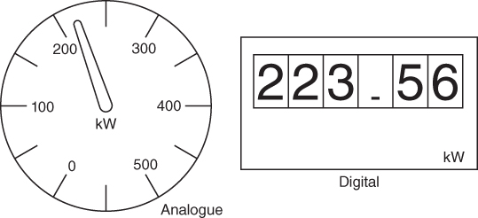
Figure 28.7 Quantitative displays.
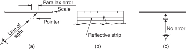
Figure 28.8 Parallax error when reading mechanical analogue displays: (a) view from above (plain), (b) front view and (c) plan.
Digital displays show the numerical information directly as a number; for example, the odometer on a car. This has the advantage that a reading to any accuracy desired can be made, provided enough numerals are on the indicator. Some digital displays are mechanical but most today are electronic, liquid crystal or LED displays. This fact leads to another advantage, that is, they are relatively easily integrated with electronic and electrical control systems. One disadvantage is that if the value is rapidly changing or fluctuating, then a quick glance may not be enough to determine the actual value, or direction and rate of change. In some instances when the advantages of both types of display are required then they are combined into the one instrument.
28.4.1.3 Representational Displays
A representational display provides a pictorial diagram or working model of a process. This must be kept as simple as possible to keep extraneous information to a minimum. Such displays would be found, for example, in large process plants, railway control rooms and electricity distribution centres. Computer screens can be used and simulation programs could be incorporated to show possible future events.
There is a wide variety of controls available for the designer to select for any piece of equipment. Knobs, buttons, horizontal and vertical levers, joysticks and handwheels are only a sample. Factors to be considered when selecting a means of control are the force required to be exerted, the speed with which this force is to be applied and the accuracy with which the process has to be controlled. For example, for delicate control a large diameter knob will allow fine, precise movements, but it will be unsuitable for rapid movements or the application of high forces. At the other extreme, a large vertical lever will allow the rapid application of a large force but would be most unsuitable for precision movements.
When designing integrated display and control elements it is important, for safety reasons, to adhere as far as possible to the conventions recognised in the country in which the equipment is used. Simple examples are: pushing a switch downward usually means ‘on’, rotating a switch clockwise also means ‘on’, but turning a water tap clockwise usually means ‘off’. If an operator rotates a control clockwise or moves a cursor from left to right, he will expect an increase in whatever value is being adjusted. A composite of some of these control and display conventions is shown in Figure 28.9 for increasing values.
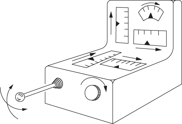
Figure 28.9 Controls and display convention.
28.4.2 The Working Environment
Environmental conditions have a strong effect on the efficiency, comfort and health of the worker. We will consider them under three main headings: lighting, noise and heating and ventilation.
28.4.2.1 Lighting
A lumen is the derived SI unit for luminous flux and it is a measure of the total amount of visible light emitted by a source. However, here we are more concerned with the total luminous flux falling on a work area, this is termed luminance and in SI units is measured in lux (in the USA foot candles are often used and one foot candle is roughly 10.76 lux). One lux is equal to 1 lumen per m2. Irrespective of which country you may be in there will be recommended minimum lighting levels provided as guidance for workspaces. Generally, the very minimum amount of light for a continuously occupied working space can be taken as 200 lux or 200 lumens per m2. With respect to manufacturing industry, this represents the minimum illumination that should be apparent throughout a factory for safety purposes. Much more light than this is needed to avoid eye strain when carrying out activities involving detailed tasks. In practice, levels of 1000 lux or higher are often necessary. A table showing typical lighting levels is shown in Table 28.3. These lighting levels can be measured quickly and simply by using easily purchased light meters.
Table 28.3 Approximate luminance requirements for interior activities.
| Lux | Typical activities or locations |
| 100–150 | Occasionally visited interiors, corridors (similar to very dark day) |
| 200–250 | Simple office work, lecture rooms and non‐detailed visual tasks |
| 300–500 | Libraries, normal office work, packing products, foundry work |
| 500–750 | Spray painting, engine assembly, moderately difficult visual tasks |
| 750–1000 | Craft work, colour judgement, food inspection (overcast day) |
| 1000–1500 | Electronic product assembly, detailed press tool making |
| 1500–2000 | Fine detail work, woven fabric and small assembly inspection |
| 2000–20 000 | Very detailed low contrast lengthy work (full daylight is 10 000 lux) |
Light sources should be chosen carefully. There are various types available, for example, incandescent, fluorescent, LED and so on. The range of sources available all have different characteristics regarding cost, power consumption, colour and amount of light produced.
The amount of light is only one factor. Other considerations should be the distribution of the light, for example, daylight coming in from side windows may only one illuminate side of the factory while the other is in deep shadow; supplementary artificial lighting will be required here. Glare is another problem. Light reflected from shiny work surfaces or instrument glasses can cause strain and fatigue. This can be avoided by proper design of surfaces and careful positioning of light sources. For instance the need to choose light sources carefully to avoid ‘veiling reflections’ on computer screens is of particular importance within the office environment.
28.4.2.2 Noise
Noise is created by vibrations and movements that cause a rapid rise and fall in the pressure of the air surrounding the vibrating or moving source. These pressure changes are propagated through the air in the form of ‘sound waves’, which we hear when they impinge on our ear drum. These sounds can be pleasant, as in soft music; they can convey information, as in speech; they can be annoying, as produced by a motorbike with a poor silencer or they can be harmful, such as those experienced at close proximity to a jet engine. In the working environment noise is often described as ‘unwanted sound’ and it constitutes one of the most widespread and frequently encountered industrial hazards. The effect of noise can be both psychological and physiological. It can lead to a decrease in working efficiency and in some cases can present a safety risk. The most significant danger from noise is its ability to damage one of our most important senses — the sense of hearing.
We recognise noise as being composed of two elements, these are the frequency and the amplitude of the sound wave. The frequency is measured in Hertz (Hz), which is cycles per second. Low frequency sound produces low notes and high frequency produces high notes. Humans can usually hear sound between 20 and 15 000 Hz, although this range decreases with age. The amplitude of the sound is measured in Decibels (dB) and this is an indication of intensity or volume. The higher the decibel number the louder the sound. A logarithmic scale is used for measuring Decibels so that a 10 times increase in intensity is measured by 10 dB. This means that if a whisper at the threshold of hearing is 0 dB and the noise of a large machining centre is 90 dB, then the machining centre is 1000 million times as intense as the whisper.
While the ear can hear from 20 to 15 000 Hz, it is not equally sensitive to all frequencies, for example, 65 dB at 100 Hz does not seem as loud as 65 dB at 1000 Hz. Overall sound pressure level in dB does not therefore provide a good measure of ‘loudness’. In order to modify objective measurements to correspond to the response of the human ear, weighting networks are used that discriminate against frequencies at which the ear is less responsive. The most commonly used network is the A‐weighting and sound pressure levels measured on this basis are denoted dB(A). All international criteria related to industrial noise exposure are based on measurements of dB(A). It is thought that industrial noise first causes hearing loss to occur in the 4000 Hz region, with most annoying noise occurring between 1000 and 4000 Hz. Figure 28.10 shows values for typical sounds in dB(A). Equipment is available to measure noise levels in dB as well as dB(A) and to isolate and measure individual frequency components.

Figure 28.10 Some Db(A) values of typical sounds.
The risk of hearing loss due to exposure to noise depends on both the level of noise and the duration of exposure. If the noise is steady, then a direct A‐weighted sound pressure level provides an adequate basis for assuming exposure. Where the noise fluctuates, as occurs in most industrial situations, the concept of the ‘Equivalent Continuous Sound Level’ or ‘Leq’ is used. This is the notional continuous level that, if experienced over the exposure period, would cause the same A‐weighted energy dose to be received by the ear as that due to the actual sound. Values of Leq must be qualified by stating the exposure period to which, the level relates. For example, in the UK The Control of Noise at Work Regulations 2005 uses the equivalent continuous sound level over a standard eight hour working shift as the basis for specifying limits of exposure. In the regulations, this eight hour Leq is termed the ‘Daily Personal Noise Exposure’, LEP.d. It states that the lower action level will be a daily or weekly exposure of 80 Db(A), the upper action level will be 85Db(A) and the exposure limit level will be 87Db(A).
The regulations clearly state that the employer in all cases has a statutory duty to reduce the risk of hearing damage to employees to ‘the lowest level normally practicable’.
For exposures at or above the first action levels a noise assessment must be carried out by a competent person to identify which employees are so exposed. Where employees are likely to be exposed between the first and second action level the employer must provide hearing protection if requested by the employee. Where exposure is at or above the second action level, exposure must be reduced to the lowest level reasonably practicable other than by the provision of personal ear protectors. If exposure is still at or above the second level then the employer must provide suitable personal ear protectors and ensure that they are worn. Such areas of high exposure must be clearly identified as Ear Protection Zones.
The problem of minimising industrial noise should, however, begin at the equipment design stage. Machines and process equipment should be designed for quiet running with minimum vibration. The next level is to ensure that machinery is properly maintained, for example, bearings lubricated frequently and replaced promptly when necessary. After this comes containment of the noise within the machine's immediate vicinity. This can be carried out by using acoustic mufflers; these are soundproofed boxes that fit around the noise source. Finally, if the noise levels are still too high, personal protection will need to be worn by the workers in the local area. This takes the form of ear plugs or ear muffs. One reason that these are used only as a last resort is that they remove the ability to hear normal noises in the work area. This can be a safety hazard; for example, a warning shout from a colleague or an approaching vehicle may not be heard. Special frequency selective hearing defenders are available to reduce this problem, but they are more expensive.
28.4.2.3 Heating and Ventilation
As mentioned earlier in this chapter, harmful atmospheric contaminants, such as paint particles, dust and gases, must be extracted from the work area or protective equipment supplied to the workers. In addition, heating and ventilation should be maintained in the workplace at such a level as to ensure physical comfort for the workers.
The Factories Act requires a ‘reasonable’ temperature to be maintained in any working space. Where work is sedentary and there is little physical effort ‘reasonable’ is often interpreted as a temperature of at least 15.5°C after the first hour of occupation. The definition and assessment of ‘comfort’ is complex, however, and depends on variables that are both personal, such as activity and clothing and environmental. For example, if some workers are physically active in operating machines or lifting material in the same area as others are sitting at a bench carrying out assembly work, then what is too warm for the first group may be comfortable for the second.
‘Thermal comfort’ therefore relates to the ease with which the body's internal energy production can be balanced by its energy loss to its surroundings. This energy loss will depend on heat transfer by evaporation of moisture from the skin to the air, and by radiation and convection of heat from the body to the surrounding environment. The required environmental conditions for comfort under different work activities have been studied by many researchers. One researcher, P.O. Fanger, and his co‐workers identified the following environmental variables that will influence comfort perceptions:
- Air temperature. This affects the amount of heat loss by convection from the body and is a very important factor for thermal comfort assessment. A wide variety of thermometric devices are available to measure air temperature, but the mercury in glass thermometer is probably still the most convenient instrument. In cases where there is likely to be a significant difference between the air and mean radiant temperatures, a radiation shield, which may simply be a piece of aluminium foil on a frame, can be placed around the bulb of the instrument.
- Air speed. Air speed affects convection as well as moisture evaporation from the body surface. The average air speed may be measured by a variety of instruments, the most commonly used at present being the hot wire anemometer. An air flow of around 0.15 m s−1 is suitable for most situations provided the air and mean radiant' temperatures are acceptable. Normally, at about 0.5 m s−1 people will complain of draughts, but at less than 0.1 m s−1 of staleness.
- Mean radiant temperature. This controls the loss of energy from the body by radiation. The traditional instrument for measurement of mean radiant temperature is the Globe thermometer, which consists of a 150 mm diameter hollow blackened sphere, normally of copper. The temperature sensor is usually a mercury in glass thermometer with its bulb located at the centre of the sphere. To assess the mean radiant temperature simultaneous readings of the Globe and air temperature and the air speed are required. An alternative to the Globe instrument is a blackened sphere of 100 mm diameter, which gives a reading of ‘dry resultant’ temperature.
- Relative humidity. This affects the degree of evaporation from the surface and is therefore of much greater importance when heavy work is being carried out and the individual is sweating. It is normally uniform throughout a space, therefore, readings are required only at one position. The normal method of measurement involves using wet and dry bulb thermometers. Relative humidity is expressed as a percentage, with values between 35% and 70% considered acceptable for most situations. Below 35% static electricity build up can cause difficulties and above 70% building fabric condensation may occur.
Thermal indices are used to express thermal comfort in terms of a single number, which is often an index temperature. Examples are air temperature (a poor thermal index when used alone), Globe temperature and dry resultant temperature. Most indices of this kind are convenient to use when assessing the suitability of environments in terms of thermal comfort. Dry resultant temperature is the index that is recommended for use in the UK. This index does not take into account relative humidity, which might also have to be measured depending on the work situation. For comfortable conditions to exist, it is recommended that the dry resultant temperature should lie between 19 and 23°C.
28.5 Conclusion
This chapter has indicated some of the human factors that must be considered by the engineer or manager in a manufacturing organisation. One whole area of concern that is not investigated here is that of ‘industrial relations’. Industrial relations is the study of social relationships within an industrial context and it involves ‘workers’, that is, non‐management personnel, management and the government. The interrelationship of these three groups can be very complex and all are involved in creating the terms and conditions within which work takes place. The character of industrial relations differs widely not only between countries but also between industries and individual companies. For example, the management style in a traditional heavy engineering company is often quite different from that in a new electronics company; this will produce different worker – management relationships and hence different types of industrial relations problems. In conclusion, it can be said that while broadly following the scale of needs mentioned at the beginning of the chapter, the aspirations of individuals within an organisation will never be exactly the same. This often leads to disagreement and conflict; it is the job of a good manufacturing manager to ensure that this conflict is constructive rather than destructive. This approach can be facilitated by also ensuring that all the human factors mentioned in the chapter have been carefully considered.
Review Questions
- 1 Do people really need to work? Give a reasoned basis for your answer.
- 2 Give examples of the type of work situation that should be avoided to ensure that a factory worker is psychologically satisfied.
- 3 How might job dissatisfaction be manifested in an employee's behaviour and performance?
- 4 What is the purpose of legislation such as the ‘Health and Safety at Work Act’?
- 5 List typical factors that should be considered to ensure the health of factory workers.
- 6 ‘All accidents are caused by someone!’ Do you agree with this statement? Why?
- 7 Discuss where accident costs are incurred.
- 8 Within the factory situation, what are the three road areas that can be considered for accident prevention?
- 9 List three types of guarding that can be employed to improve safety when machinery is being used.
- 10 Who has the responsibility for safety within a factory? Discuss the functions of the personnel you describe.
- 11 Describe the work of an ergonomist.
- 12 Discuss how anthropometrics can be used to assist in the design of healthy, safe and easy to use equipment.
- 13 Describe the three main types of display used in industrial equipment and explain the type of application to which each is suited.
- 14 What is the ‘control convention’ in integrated display and control elements?
- 15 Name three aspects of lighting that should be considered to ensure worker efficiency in the factory or office environment.
- 16 Why is it extremely important to give attention to the noise levels in a work area?
- 17 Describe the two elements of which noise is composed and discuss their relevance to the employer and the employee.
- 18 Discuss what is meant by the ‘equivalent continuous sound level’ (Leq) experienced by workers.
- 19 At what four levels should machinery created noise problems be tackled in an industrial situation?
- 20 Discuss fully the factors that contribute to the thermal comfort of a worker; include in your answer comments on how they are measured.