
9
Cutting Processes
9.1 Introduction
There are a number of ways to cut materials and in this section we will consider some of the most popular. The first to be considered, and the most widely used in manufacturing industry, is machining. This generally involves using a cutting tool that removes material by chip formation. Another method is thermal cutting, this involves separating metal by localised heat using for example gas, electric arc or laser. Both of these methods are considered here in relation to metal cutting although machining by chip formation is also used for a wide variety of other materials. Finally, water jet cutting will be considered; this is popular for cutting polymers and composite materials when using industrial robots.
9.2 Sawing and Filing
Both sawing and filing involve cutting the material by chip formation. In sawing, a narrow strip of metal called the blade has a series of cutting teeth arranged along its edge. Although hand saws of various types have been used in woodworking for hundreds of years, modern industrial power saws used for cutting metal in the manufacturing industry are normally of three types. First, the hacksaw has a blade of limited length and is only slightly flexible; it is often used for cutting rods and bars to specified lengths. Second, the bandsaw has a flexible blade formed into a continuous band. The blade is usually made mainly of flexible high tensile strength alloy steel with tungsten carbide or high speed steel teeth bonded to one edge. The blade passes round two wheels, one of which is driven while the other maintains the tension. This blade passes through a slot in a worktable on which the material to be cut rests. The bandsaw can be used for cutting shapes from sheet and plate materials. Finally, the circular saw is a rigid disc with cutting teeth around the circumference. This is used for fast cut off operations and it usually leaves a clean smooth cut surface.
In filing, the cutting operation is similar to that of a saw except that the cutting teeth are much broader and arranged in series on a relatively broad rigid surface. Because only small amounts of material are removed, filing is not used to separate or cut off material but is used to obtain precise shapes and dimensions on a workpiece. Files can vary greatly in size and shape. Large coarse files are used for removing large amounts of material quickly; at the other end of the spectrum small fine toothed needle files are used for delicate work, and a wide variety of file cross‐sections are available, for example, flat, round, square, triangular and so on. Filing machines use file segments joined to form a continuous band analogous to the handsaw, circular files are used in disc filing machines and straight solid files, similar to those that are hand held, are used in reciprocating die filing machines.
9.3 Basic Principles of Machining
In machining, a ‘cutting tool’ is held in a ‘machine tool’ such as a lathe, drill or milling machine. The machine causes relative movement of the tool with the work such that the material is cut. As the tool enters the work and moves through it a chip is produced, hence the term ‘chip removal’; the operation of a single point tool is shown in Figure 9.1. Cutting tools may have more than one cutting edge; for example, a drill usually has two, a milling cutter may have 22 and the small hard particles that are the cutting edges on a grinding wheel can be numbered in their millions.
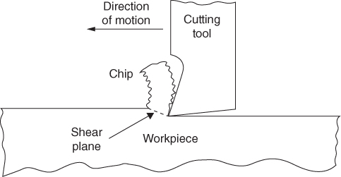
Figure 9.1 Two‐dimensional (orthogonal) cutting using single point tool.
9.3.1 Advantages and Disadvantages of Machining
Advantages of machining are as follows. Generally speaking, machining is the best manufacturing process for achieving high precision components with specific surface finish characteristics. It is possible to achieve very high production rates with automated machines yet batch sizes from single units upwards can be economic. For manually operated machines the capital cost of equipment can be relatively low. Complex shapes can be made by machining particularly when multi degrees of freedom computer numerical controlled (CNC) machines are used. Disadvantages of machining include the production of scrap due to the chip forming nature of the process and the limited life of cutting tools. Skilled, and hence expensive, labour may be required. Machining may require more energy and some geometric shapes may take much longer to produce than other processes. Also unless cutting conditions are carefully controlled, machining can adversely affect the surface properties of the workpiece.
9.3.2 Single Point Cutting Tools
In lathe work a single point cutting tool is often used; it is also useful here for illustrating a tool's basic geometry, see Figure 9.2. It is apparent that the shape of a metal cutting tool is quite different from a knife or a woodworking chisel, that is, the metal cutting edge appears much thicker. This is for two main reasons. First the tool is subject to very high loads when cutting strong and often hard metals, therefore the tool itself must be strong. It also has to be harder than the metal it is cutting, this makes it relatively brittle, hence the need for support behind and below the cutting edge.
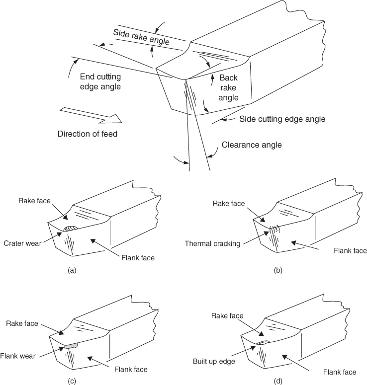
Figure 9.2 Single point cutting tool for lathe turning. (a) Crater wear. (b) Thermal cracking. (c) Flank wear. (d) Built‐up edge (BUE).
9.3.3 Chip Formation
Referring again to Figure 9.1 it can be seen that as the cutting tool moves through the workpiece material a strong force is directed by the tool into the workpiece in a direction at right angles to the rake angles. This force increases until the material shears in the direction of the force and the area over which this occurs is called the ‘shear plane’. Depending on the machinability of the workpiece material, the cutting tool material, the speeds and feeds used, the depth of cut and the rigidity of the machine and tool, different types of chip can be formed: two are considered here.
- Discontinuous chips. These are usually formed when the material being cut is brittle and relatively hard. One of the reasons chip discontinuity occurs is that the material cannot resist the high shear forces mentioned previously and therefore separate chips or even a fine shower of material is created. Other causes are large chip thicknesses resulting from coarse feed rates and low cutting speed, negative or small positive rake angles on the cutting tool, inefficient lubrication or cutting without a cutting fluid. An advantage of the discontinuous chip is that chip disposal is easier. Disadvantages are that the fluctuating cutting forces can cause tool chatter and vibration, thus spoiling surface finish, this can be minimised by ensuring the cutting tool, tool holder and material being cut are all rigid.
- Continuous chips. These are usually formed when the material being cut is ductile and relatively soft. Surface finish is usually better since tool chatter is less likely to happen than with discontinuous chips. They often occur with high cutting speeds, large cutting tool rake angles, sharp cutting edges and where there is low friction between the chip and tool face – normally due to good lubrication and a smooth tool face. However, a disadvantage is that they can be very long and sharp coiling around the workpiece and other parts of the machine, thus being very dangerous to handle. A way of overcoming this is to use a ‘chip breaker’. This is a small component clamped to the top of the tool that forces the chip to curl so tightly that it hits the workpiece and breaks off into smaller pieces.
9.3.4 Cutting Tool Wear
Due to the forces acting on the tool during cutting, the abrasive nature of chip production and high temperatures, the cutting tool will experience wear. This wear will eventually affect the cutting process such that the surface finish on the material being cut will degrade, the workpiece may go out of tolerance and the cutting forces will rapidly increase. The tool should therefore be changed or resharpened before any of these damaging effects occur.
Crater Wear is found on the rake face of the tool just behind the cutting edge, see Figure 9.2 a, and it is created by the rubbing of the chip across the face, by high temperatures at the tool chip interface and a chemical affinity between the tool and workpiece materials.
Thermal Cracking is caused by high temperatures, see Figure 9.2 b. These cracks occur at right angles to the tool cutting edge and can lead to chipping of the tool; this will spoil the surface finish of the workpiece as well as reduce the life of the tool.
Flank Wear is found on the clearance angle of the tool and is caused by the rubbing of the tool along the surface of the workpiece, see Figure 9.2 c. A result of this is the creation of undesirably high temperatures, adhesion and abrasive wear, all of which reduce the properties of the tool.
A Built Up Edge (BCE) is formed by particles of the workpiece material that are gradually built up in welded layers onto the rake face of the tool while cutting, see Figure 9.2 d. The BUE can increase until it dislodges from the tool and is partly carried away by the chip and partly left adhering to the surface of the workpiece. Therefore, large BUEs are very undesirable since they can spoil the surface finish of the workpiece and reduce cutting tool life, a thin BUE, however, is seen as desirable since it protects the rake face of the tool and reduces frictional wear.
9.3.5 Cutting Tool Materials
A cutting tool requires to be hard, tough and wear resistant. Until the early years of the twentieth century high carbon alloy steel was able to satisfy these requirements. However, as the need for higher cutting speeds increased so the need for cutting materials that held their hardness, toughness and wear resistance at high temperatures also increased. This led to the use of ‘carbide’ cutting tools in the 1930s. The tool composition was in fact particles of tungsten carbide bonded into a matrix of cobalt for cutting non‐ferrous metals and cast iron, or titanium carbide for use at higher cutting speeds when cutting harder materials such as steels. These tools are still used today in the form of disposable tool inserts, see Figure 9.3. Many other cutting tool materials are now available. Because of their cost they are used in the form of indexable inserts. Ceramic, cubic boron nitride, which is almost as hard as diamond, and diamond itself are examples. Suitable materials can also be used to coat the surface of a base material, for example, titanium nitride can be used to coat high speed steel tools.

Figure 9.3 Indexable insert.
9.3.6 Cutting Parameters
Three critical parameters in machining are the speed of cutting, the depth of cut taken and the rate at which the cutting tool is fed into the work; this is illustrated for a turning operation in Figure 9.4. These are determined by considering the rate at which material is to be removed, the type of material being cut and the material of the cutting tool being used, the surface finish required, the power of the machine tool and the amount of support given to the work. For a fast material removal rate the cutting speed, feed rate and depth of cut all need to be maximised. Tough or hard materials being cut will reduce the material removal rate and hard and tough cutting tool materials will allow it to be increased. Generally speaking, high feed rates with single point tools produce coarse surface finishes, smooth surfaces being obtained by using high cutting speeds, low feed rates, shallow depths of cut and cutting tools in good condition.
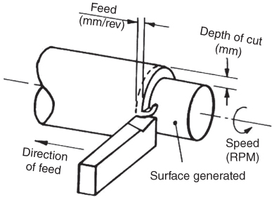
Figure 9.4 Generating a surface.
Cutting tools can be used to create the shape of a workpiece by either ‘generating’ or ‘forming’ the surface. In generating, the shape of the surface produced is determined by the nature of the movement of the cutting tool relative to the workpiece. Thus in turning, a cylindrical shape is generated when the tool moves parallel to the rotational axis of the workpiece, see Figure 9.4 .
Using turning again as an example, a surface can be formed as shown in Figure 9.5. In this case, the tool is fed straight into the work at right angles to the rotational axis and the final shape of the surface is determined by the shape of the cutting tool.
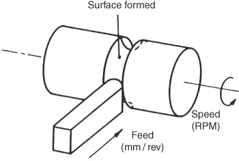
Figure 9.5 Forming a surface.
9.3.7 Machinability
The machinability of a material is an indicator as to how easily it can be cut to provide a good surface finish and precision. With metals the metallurgical structure and chemical composition; the hardness, ductility, yield and tensile strengths; susceptibility to ‘work hardening’ and the presence of inclusions, will all affect the machinability. A metal that has good machinability, called a ‘free machining’ metal, is good economically and environmentally since it will (i) minimise the cost of machining by being able to be cut quickly, (ii) need relatively low power therefore requiring less energy than a more difficult material and (iii) it will produce less wear on the cutting tool.
Softer materials such as aluminium are easier to machine than, say, stainless steel. However, if a material is too soft problems can arise. For example, low carbon steels are softer than high carbon but have a tendency to stick to the cutting tool; this results in the built‐up edge noted earlier that shortens tool life. Low ductility makes cutting easier since chip production is facilitated but increased hardness will cause increased tool wear and demand higher power for cutting. A compromise between hardness and ductility is therefore often necessary. High thermal conductivity in the material being cut is good since the heat generated at the cutting tool tip is carried away quickly thus increasing tool life. Substances included in the material in trace amounts are called inclusions. These may increase or decrease the machinability. For example, aluminium oxide, which is hard and abrasive, will decrease machinability whereas manganese sulfides, which reduce the steel's strength, will increase machinability.
9.4 Machine Tools
The variety of machine tools available is large; there are those that are manually operated, those that are computer controlled and those that are specially designed for specific operations – these may be controlled mechanically, pneumatically or electronically. The ones we will examine in this section are the universal manually operated types. These might be found in a toolroom where possibly only a single component is to be made at a time. Today lathes, milling machines and machining centres are often ‘numerically controlled’, that is, a computer is incorporated in the machine control system. No matter what the method of control, the basic principles of operation are the same as discussed here.
9.4.1 The Lathe
The lathe is the most widely used general purpose machine tool. Machining operations on a lathe involve rotating the workpiece and generating a surface. When the surface is external and parallel to the rotational axis the cutting process is termed ‘turning’, when cutting an internal surface the term ‘boring’ is used and when creating a surface at right angles to the rotational axis a ‘facing’ operation is being carried out, when cutting a component off from the material held in the lathe workholder, the process is called ‘parting off’. Screw threads are often cut using a lathe and this operation is termed ‘screwcutting’. These operations are shown in Figure 9.6.

Figure 9.6 Some machining operations carried out on a lathe.
There are many different types of lathe, each suited to different production volumes and types of product. Three are outlined here to explain the essential principles of operation. The basic type is called a centre lathe since the workpiece may be held between a revolving powered centre in the lathe headstock and a free centre mounted in the tailstock. This type was also known as an engine lathe, the term arising from when they were first used in factories and driven via pulleys and shafts from a common steam engine. The basic construction of this lathe is shown in Figure 9.7.

Figure 9.7 Basic elements of a centre lathe.
The main body of the lathe is termed the bed. This supports and contains all the other lathe components; a large portion of it may be made from cast iron or other materials such as concrete or a granite‐epoxy composite to absorb vibration. On the top of the bed are two sets of surface hardened precision machined slideways; these are parallel, straight and flat. They hold the headstock and tailstock and guide the carriage. The precision of the whole lathe is determined by the precision of these slideways. The motors to drive the lathe may be mounted in the bed or ‘headstock’. The headstock holds the gear trains to allow a variety of cutting speeds and feeds to be selected. The headstock also contains the hollow spindle that drives the workpiece holder. The gearing in the headstock transmits drive to the lead‐screw and the feed rod. The lead‐screw is engaged to the carriage when cutting screw threads. The feed rod rotates and causes movement of the carriage and cross slide during operation of the lathe. The apron contains the components for transmitting the movement from the lead‐screw and feed rod to the carriage and cross slide. The carriage, or saddle, can move parallel to the major axis of the lathe and supports the cross slide. The cross slide rests on guides on the carriage and can move at right angles to the major axis; it holds the tool post that carries the cutting tools. When cutting the tool is clamped tightly into the toolpost or toolholder. The tool must be rigid with the minimum of overhang otherwise it will vibrate or ‘chatter’ and produce a poor surface finish on the component. Both the carriage and the cross slide can be fed by hand or machine drive by engaging or disengaging the transmission.
In operation, the workpiece is attached to the spindle via a number of alternative workpiece holders. For example, if the component being machined is long a centre will be inserted into the spindle and a driving plate attached; the other end of the work will be held in the centre contained in the tailstock. If the work is very long a roller support will be placed opposite the cutting tool to prevent deflection of the work due to cutting forces. More often a chuck will be used as the workholder, see Figure 9.8. These have either three or four jaws. The jaws of the three jaw chuck move in unison when clamping a component; they are therefore useful for holding circular bar or previously turned components. The jaws of four jaw chucks move independently and are therefore used for clamping and centring non‐circular components. Collets are quicker to use than chucks and are again used for circular components, see Figure 9.9. They are hollow, therefore they can be used when machining components from long lengths of bar. The bar can be held in a support and passed through the hollow spindle and collet in the headstock. The collet clamps the material and the turning operation is carried out. On completion the component is parted off, the collet then unclamps and the bar is fed through the required length for the next component.
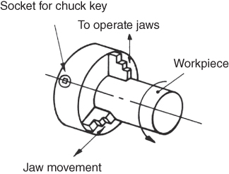
Figure 9.8 Three‐jaw chuck (3 and 4 jaw chucks usually much larger than collets).
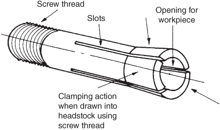
Figure 9.9 Round collet for cold rolled or previously machined material (openings may also be square or hexagonal).
Although the centre lathe serves well to explain the basic turning operations, it is not suitable for high volume production work. One that is suitable is the turret lathe. In this lathe a multi‐sided indexable toolholder or ‘turret’ is mounted on the near side of the cross slide; a toolholder with a parting off tool is often mounted on the opposite side and another multi‐sided turret (often hexagonal holding six tools and called the main turret) is mounted on a ram in place of the tailstock. These machines often operate automatically and are able to carry out multiple operations, such as turning, drilling, boring, screwcutting, facing and parting off, on the same workpiece very quickly.
Another type of lathe used for very high volume work is the multi‐spindle screw machine. Here rather than one spindle a number of hollow spindles are used, each being fed by long rods of material from a rod holder and feeder; there may be four, six or eight spindles. Mounted on an end slide there will be a number of toolholders and tools equal to the number of spindles. This slide does not rotate but feeds the tools axially to the workpieces. There will also be tools mounted radially on cross slides. In this machine, all tools cut simultaneously then withdraw to allow the spindles to index round to the next position. The cutting operations are therefore being carried out in parallel rather than in series. This means that a product can be produced every few seconds, the cycle time being governed by the longest cutting operation.
9.4.2 The Milling Machine
Just as the lathe is the most used machine for producing rotational or cylindrical components, the most used machine for producing non‐rotational or prismatic components is the milling machine. Again there are several types, but here the principles of operation can be examined by considering just two – the knee type horizontal and vertical mills, see Figure 9.10.
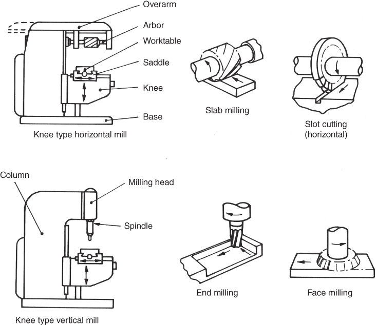
Figure 9.10 Horizontal and vertical milling.
These machines have the following major components: a base, column, knee, saddle, worktable, overarm, milling head, spindle and cutter. The base supports the other elements and therefore should be made of a material that has strong compressive strength and can absorb vibration, for example, cast iron. The worktable rests on the saddle, which is supported by the knee; this is a cantilever unit guided by slideways on the column. The saddle provides vertical adjustment and the saddle and the table allow mutually perpendicular horizontal axes adjustment. The column contains the motors and gearing to drive the spindle. In the vertical type mill the spindle is vertical and is held in the milling head. In the horizontal machine the spindle is horizontal and drives an arbor that holds the cutting tools; an overarm is used to provide outboard bearing support.
Some milling cutters are shown in Figure 9.11. Figure 9.11 a shows a light duty cylindrical, or slab, cutter for surface milling on a horizontal mill; in general, the heavier the duty the greater will be the helix angle relative to the axis and the fewer the number of teeth. The helical form allows each tooth to engage the work gradually and, since more than one tooth is usually in contact with the work at any moment, shock and chatter are reduced, thus producing a smoother surface. The keyway is to allow the cutter to be keyed to the arbor to prevent slippage. Many other types of cutter are used on the horizontal mill, most of them being disc shaped. For example, there are slitting saws for cutting through the material, slotting cutters for producing slots of specified depth and thickness and form cutters for producing any desired profile. Figures 9.11 b,c show an end mill and slot drill, respectively; these are used in vertical milling. The end mill has a number of teeth, for example, four, on the circumference and one end. It is used for creating flat horizontal and vertical faces and for profiling. The slot drill usually only has two teeth on the circumference and end. It is designed to cut while sinking into the workpiece or traversing across it and is often used for creating slots and keyways.
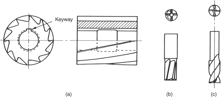
Figure 9.11 Some milling cutters. (a) Cylinder or slab cutter. (b) End mill. (c) Slot drill.
In milling, the direction of cutter rotation relative to the direction of feed is important. The two methods of cutting are shown in Figure 9.12 for horizontal milling. Conventional or ‘up’ milling is shown in Figure 9.12 a. Here the maximum chip thickness occurs at the end of the cut. This means that, provided the cutting teeth are sharp, the tool life is not unnecessarily reduced due to workpiece surface quality and the cut will be smoother. Disadvantages are that there is a disposition towards chatter, the work tends to be pulled upward off the table thus making effective clamping essential and the chips or cuttings are liable to pile up in front of the cutter, thus causing it to constantly have to cut its way through previously cut material. Figure 9.12 b shows climb or ‘down’, milling. Here the maximum chip thickness occurs at the beginning of the cut. It has the advantages of tending to assist the clamping action by pushing the workpiece down onto its location; this makes it suitable for slender or flexible workpieces, also the chips are deposited behind the cutter, making the cutting process more efficient. Disadvantages are that due to the impact made by the cutter as it enters the work the surface should not have any surface scale as this will greatly reduce the tool life; also, since the cutter tends to pull itself into the work, backlash in the system must be reduced to a minimum. This is to avoid the cutter taking unpredictable ‘bites’ into the workpiece that would create shock loads causing damage to the tool and other parts of the machine.

Figure 9.12 Methods of milling. (a) Conventional or ‘up’ milling, maximum chip thickness at the end of cut. (b) Climb or ‘down’ milling, maximum chip thickness at the beginning of cut.
9.4.3 The Drilling Machine
Drilling is probably the most common operation in machining and although it is relatively simple it can present difficulties. These difficulties usually arise because the cutting tool, that is, the drill, has a large length to diameter ratio and is therefore flexible. Also when drilling deep holes a build‐up of cuttings in the hole will cause the drill to jam and even break; provision must therefore be made to allow these cuttings to be removed. Drilling can be carried out on a lathe or vertical mill, but often a ‘drilling machine’ is used. The basic construction of a hand operated vertical drill press is shown in Figure 9.13; this type is also sometimes called a pillar or column drill. The work being drilled may be held in a ‘drill jig’, which is hand held and free to move in the horizontal plane, the drill being guided to the appropriate points by passing through drill bushes held in the drill jig. The horizontal compliance is necessary to prevent the drill being twisted due to slight positioning errors. This differs from a ‘fixture’ used in milling that clamps the workpiece rigidly to the milling table. Other types of drilling machines are: gang drilling machines that have a number of drilling heads in a line, the workpiece being passed from head to head for each required drilling operation; multiple spindle machines that can drill a number of holes in a component in one operation; radial drilling machines that have the drill head mounted on a radial arm, which can rotate around the support column – these are used for large workpieces and, finally, turret drills, which can have a number of drills mounted on an indexable turret – these are often numerically controlled.
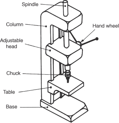
Figure 9.13 Hand operated vertical drill press.
The structure of the widely used twist drill is shown in Figure 9.14. It has three basic parts, the conical point, the body and the shank. The shank is held in the drill spindle or chuck and may be tapered or parallel. The body has helical grooves, often two, called flutes along which the cuttings travel upwards and coolant can travel downwards. The remaining surface of the body is termed the ‘land’. Immediately behind the cutting edge the full diameter of the drill is maintained for a short distance before the body diameter is reduced to provide the clearance necessary to minimise friction. This short distance may simply be termed the ‘land’ (British) or given the name ‘margin’ (US). At the point of the drill the lands terminate and where they meet with the leading edge of the flutes they form a cutting edge or lip. The core of the drill is termed the web; this provides strength to the drill and is really its backbone. Where the web meets the point a chisel edge is produced. When the drill is rotating the speed of the centre of this edge is virtually zero; this of course reduces the cutting efficiency and therefore increases thrust forces, causes deformation and creates unwanted heat. When drilling large diameter holes the problem is removed by first drilling a small diameter pilot hole; otherwise the problem can be reduced only by making slight modifications to the shape of the web at the point.
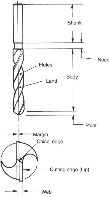
Figure 9.14 The twist drill.
Various other cutters are used in drilling machines and some of these are shown in Figure 9.15. Combination centre and countersink drills provide starting points for subsequent drilling. They are also used for drilling workpieces that will subsequently be turned between centres in a centre lathe; the countersink provides protection for the edge of the centre hole. Countersinks provide chamfers on the edges of previously drilled holes; this removes the sharp edge and acts as a lead in for subsequent insertion of screws, bolts and so on. They are also used for providing recesses for countersunk head screws. Counterbores are used for increasing the diameter of the previously drilled hole a short distance below the surface; again the hole can be used for recessing bolts and screws. Reamers are used for removing very small amounts of material from a previously drilled hole; they leave a smooth straight surface of high dimensional and geometric precision. Taps are used for producing screw threads in holes; tapping is not a drilling operation but it is often carried out at slow speed in drilling machines.
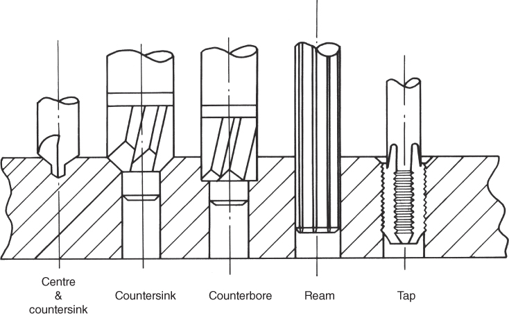
Figure 9.15 Some operations that can be carried out on a drilling machine.
9.5 Other Cutting Processes
There are many other machine tools, but those mentioned in the previous section serve to illustrate the basic principles involved. This section briefly discusses some of the other cutting processes available.
9.5.1 Thermal Cutting Processes
Processes that use heat to cut material include oxyfuel cutting, plasma arc cutting and laser beam cutting.
- Oxyfuel cutting is very widely used for cutting ferrous and non‐ferrous metals, the oxygen that supports combustion is mixed with another gas such as acetylene or propane to give the oxyacetylene and oxypropane cutting processes. For non‐ferrous metals the material is melted by the flame produced by igniting the mixed gases and blown away to form a cut known as the kerf. With ferrous materials the oxidation process is used. In order for the metal to be raised to a high enough temperature for oxidation, that is, ‘burning’ to start, a gas‐flame torch is used. This takes in oxygen and the fuel gas from separate supplies and mixes them to raise, for example, the temperature of steel to around 870 °C. Once the combustion starts the oxygen required for the reaction continues to be supplied by the torch and theoretically no additional heat need be added. In practice, the fuel gas continues to be fed to compensate for heat lost by conduction, convection and radiation. Handheld cutting torches are commonly used, but for large scale work, for example in cutting steel plate in ship production, numerically controlled machines arc used. These machines have one or more cutting torches mounted on an overhead gantry that traverses the plate being cut. The process is used to cut profiled shapes in sheet and plate, and is also used to prepare edges of plate for subsequent welding. Accuracies of ±1 mm are common, although closer tolerances are possible under carefully controlled conditions. Cutting speeds are normally in the range of 100–2000 mm min−1.
- Plasma arc cutting differs from oxygen cutting in that plasma is not dependent on a chemical reaction with the material being cut, as in the oxidation of steel. In the basic process, an electric current in the form of an arc is passed between a tungsten electrode and the workpiece; this is called a ‘transferred’ arc. In addition to the arc, which provides the highly concentrated heat to melt the metal, a high velocity gas stream removes the metal from the kerf. The gas is supplied through a nozzle around the electrode. Thus whereas the oxygen cutting process is exothermic developing large amounts of thermal energy, the plasma cutting is endothermic, requiring large amounts of energy to be put into the process. This process provides extremely high temperatures, around 33 000°C, and is therefore ideal for cutting metals, in particular the high alloy or stainless steels and non‐ferrous metals that are not so easily cut with the oxygen process. Cutting speeds of around 8 m min−1 are possible in 6 mm aluminium. The combination of high temperatures and the jetlike action of the plasma produces narrow kerfs and very smooth surfaces.
- Laser cutting utilises the fact that laser light can be focused to a very small focal point thus permitting very high power densities. The heat created at the point is used to melt or evaporate the material being cut. High power carbon dioxide lasers are now widely used in industrial applications. The laser is useful as a cutting tool only on materials that will absorb the laser light to a large extent. With the carbon dioxide laser wood and plastics cut easily; however, the absorption rate on mild and stainless steels is only 16–20%. For this reason a high pressure oxygen jet is usually used around the laser beam to assist oxidation of the material, the resulting temperature being in the region of 11 000°C. Laser cutting produces a high quality cut edge, with a very narrow cut width. The area around the cut is not adversely affected by heat and metal distortion is low.
9.5.2 Water Jet Cutting
In this process, a jet of high pressure clean water from a waterjet gun is directed at the material being cut. The water pressure is very high at around 3500 bar and the jet narrow, between 0.2 and 2.5 mm wide. The material being cut is usually lightweight glass reinforced plastic or carbon fibre a few millimetres thick. On materials such as these cutting speeds between 50 min s−1 and 125 mm s−1 are achieved. It is used to trim excess material, or cut internal and external profiles, on three‐dimensional components such as crash helmets and car door and body panels. Because the jet is hazardous the process is very appropriate for robotisation. The water jet gun is mounted on the wrist of an industrial robot that will probably have six degrees of freedom. The work is also sometimes mounted on a programmable computer controlled turntable to provide maximum manoeuvrability.
Review Questions
- 1 State four advantages and four disadvantages of using metal removal (machining) processes to create a product. (8 marks)
- 2 Name three types of saw and their uses. (6 marks)
- 3 What are the two essential qualities of a cutting tool? (2 marks)
- 4 What is the purpose of using materials other than tool steel for making cutting tools? Name two such materials. (6 marks)
- 5 Explain the two basic machining methods for producing shape. (4 marks)
- 6 Fully discuss the factors that influence how a material is machined; refer to the desired qualities of the finished component, machinability and the cutting parameters. (10 marks)
- 7 Describe the conditions that lead to the production of a continuous chip when machining and discuss, with reasons, whether or not you think this type of chip is desirable. (6 marks)
- 8 Describe the conditions that lead to the production of a discontinuous chip when machining and discuss, with reasons, whether or not you think this type of chip is desirable. (6 marks)
- 9 Name three types of cutting tool wear that occur when machining and briefly note the measures that can be taken to ensure maximum tool life. (6 marks)
- 10 With respect to metal cutting what do you understand by the term ‘built up edge’ (BUE) and what is its significance? (5 marks)
- 11 Describe five basic components of a centre lathe and their function. (10 marks)
- 12 Describe three methods of holding a workpiece in a lathe and state when and why each would be used. (6 marks)
- 13 Name one type of lathe suitable for high volume production and very briefly describe its construction. (5 marks)
- 14 What are the basic components of a horizontal milling machine? Illustrate your answer with a sketch. (10 marks)
- 15 Name three types of milling cutter and give examples of their use. (6 marks)
- 16 What are the differences between ‘up’ and ‘down’ milling? (4 marks)
- 17 Briefly, and by means of a sketch, describe the construction of a twist drill. (5 marks)
- 18 Apart from drilling, name three operations that can be carried out on a drilling machine? Include brief sketches to illustrate your answer. (6 marks)
- 19 Describe the oxyfuel cutting process. (4 marks)
- 20 Describe the plasma arc cutting process. (4 marks)
- 21 Describe the laser cutting process. (4 marks)
- 22 Discuss the relative advantages and disadvantages of the three thermal cutting processes, and give examples of where each would be used. (10 marks)
- 23 Describe the water jet cutting process. (4 marks)
- 24 Discuss why you think water jet cutting is becoming more popular in manufacturing. (5 marks)