
10
Deformation Processes
10.1 Introduction
There are at least three ways in which to classify deformation processes. One is to use the terms ‘bulk’ deformation and ‘sheet’ forming. Bulk deformation implies that the ratio of the surface area to the volume is relatively small and that the process will significantly alter the cross sectional area and shape; an example of this is forging. It is this bulk deformation that is considered in this chapter, it is an important process as it can provide fine control over the grain structure of a component and hence impart directional strength properties. Sheet forming involves changing the shape of material without significantly changing the cross sectional area; examples of this are blanking, bending and drawing and these are considered in Chapter 11.
Another classification uses the terms ‘primary’ and ‘secondary’ deformation. Primary deformation signifies the changing of shape of a piece of material from its cast ingot form into another shape. Examples of this would be rolling, forging and extrusion to produce standard shapes such as slabs, billets or rods. Secondary forming processes take the output from the primary process and further work the material to produce a finished or semi‐finished product. These processes may again be rolling, forging or extrusion, but this time typical products would be foil, bolts or window frames.
A third classification relates to the temperature at which the deformation work is carried out. Thus a deformation process may be termed ‘cold’, ‘warm’ or ‘hot’ working.
- Cold working is carried out when the material is worked well below its recrystallisation temperature (recrystallisation was discussed in Chapter 6). If the material is strain hardening then the deformation that occurs when cold working produces improvements in strength, hardness and surface finish when compared to working at higher temperatures. No energy needs to be expended on heating and contamination of the component is minimised. Cold working also allows better dimensional control that in turn facilitates production of interchangeable components. However, higher forces are required for deformation, hence the necessity for heavier and more powerful equipment. Cold working also reduces the ductility of the material; this may cause it to fracture after a number of deformations have taken place unless annealing is carried out between deformations. Imparted residual stresses and directional properties can also be detrimental unless carefully controlled.
- Warm working is carried out below the recrystallisation temperature but above normal cold working temperatures. Compared to cold working it has the advantages of reducing the forces required for deformation and compared to hot working it provides better dimensional control. The exact temperature at which it can be carried out depends on the material.
- Hot working is carried out above the material recrystallisation temperature. At these elevated temperatures the material strength is reduced and its ductility increased thus making it easier and cheaper to deform. Large changes of shape can be made without the material cracking. The structure is improved as internal pores are welded shut and impurities distort and flow along the grain structure – this allows directional properties to be selectively imparted. Disadvantages are the need to heat the material, poor dimensional control and the oxidation of the material surface. As well as producing a poor surface on the hot worked product the oxidised layer can also be disturbed and forced into the material as it is worked, making the achievement of a good surface finish difficult at subsequent machining operations.
10.2 Rolling
Rolling involves squeezing the material between rollers rather in the way that an old fashioned mangle or wringer was used to squeeze clothes dry. Large reductions in section are made by hot rolling the material. Only when finishing rods, strip, sheet and foil is cold working used since changes in section are slight and high surface finishes are desired.
In the past the raw material for rolling was always a cast ingot; however, with the increasing use of continuous casting in integrated steel plants, more rolling of ‘concast’ slabs is carried out. In the most general case, rolling steel from the ingot, the process can be described as follows. While still hot, the ingots are placed in gas fired furnaces called soaking pits. There they remain until they have attained a uniform working temperature of about 1100°C throughout; this is well above the recrystallisation temperature but still below the melting point, which for steels is between 1370 and 1530°C. The ingots are then taken to the rolling mill where they are rolled into blooms, billets or slabs. A bloom has a square cross section with a minimum size of approximately 150 mm2. A billet is smaller than a bloom and may have any square section from about 40 to 150 mm2. Slabs may be rolled from either an ingot or a bloom, they have a rectangular cross section with a minimum width of 250 mm and a minimum thickness of approximately 40 mm. The width is about three or more times the thickness, which can be over 300 mm. The principle of operation of a rolling mill is shown in Figure 10.1.

Figure 10.1 Principle of operation of a two high reversing mill for steel rolling.
The mill used for rolling an ingot into a bloom is known as a ‘cogging mill’ and is generally of the two high reversing type. The heated ingot is placed on a conveyor comprised of powered rollers. These power driven rollers are provided at both sides of the mill, and since they also are reversible the ingot can be passed to and fro between the pressure rollers. The whole process is monitored and controlled from an overhead pulpit that is equipped with instrumentation and closed circuit television screens. From here the power driven manipulators can be controlled that allow the ingot to be turned over, moved laterally and even straightened while on the conveyors. It is important to ensure the metal is maintained at a uniform pressure as this controls metal flow and plasticity. The rolls themselves are cooled by running water over them to ensure that they maintain their own strength and hardness properties. The rollers gradually wear in use and therefore need to be removed periodically for turning in a lathe to restore their original profile. The rollers for making smooth flat plates would be ground rather than turned (see Chapter 9 for a turning and grinding description).
The mill used for rolling ingots into slabs is known as a ‘slabbing’ mill. It is very similar in construction to a cogging mill but with a few differences. Since a slab is much wider than a bloom and the width to height ratio of the section is high, the rollers require a long flat profile and the lift of the top rollers must be sufficient to allow the edges of the slab to be rolled when lying on its side. There are also high pressure water sprays incorporated to dislodge the scale from the wide surface of the slab.
Subsequent rolling operations allow blooms to be rolled into large round bars, small slabs and heavy sections such as ‘I’ beams; many are also rolled into billets of approximately square section with rounded corners. Further rolling of billets converts them into rod, bar and structural sections such as T beams and angle and channel sections. Further rolling of slabs produces plates; these can be again rolled to produce sheet, which could then be rolled to produce foil. These subsequent operations are carried out in rolling mill ‘stands’ of a variety of configurations, some of which are shown in Figure 10.2.
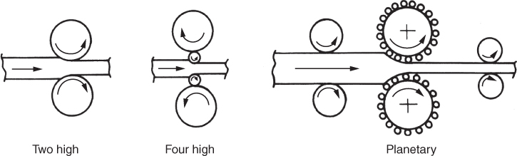
Figure 10.2 Some rolling mill configurations.
To produce strip from slabs, for example, a number of stands are arranged in a line. The hot slab enters the first stand where it is reduced in thickness. As it emerges its speed is much faster than when it entered, therefore, the next stand in sequence must be ready to accept it at this higher speed. There will be a number of stands and by the time the material is passing through the last one it is being cold worked and travelling at extremely high speed. It emerges from the stand onto a coiler where the strip is wound ready for dispatch to the customer.
In the rolling stand, the smaller the diameter of the roll used, the shorter will be the length of contact of the roll circumference for a desired reduction in material thickness. This means that a higher pressure is exerted on the material, thus producing a greater deformation. The disadvantage is that the decreased size of the rolls reduces their stiffness. Therefore, to prevent their deflection under load, back‐up rolls of thicker section are required. This leads to configurations such as the ‘four high’ and ‘planetary’ arrangements shown in Figure 10.2 , which allow large reductions in section to be performed in a single pass.
Typical rolled products would be plates for building ships' hulls; structural beams of various sections for the construction industry; hexagonal section bar for making nuts and bolts; steel sheet for making panels for cars, washing machines and cookers; copper alloy strip from which small components such as electrical terminals could be blanked and aluminium foil.
10.3 Forging
As with rolling, forging can be carried out hot, warm or cold, depending on the characteristics required in the finished product. In forging, plastic flow takes place in the material when it is subjected to compressive forces via presses or hammers. Figure 10.3(a) shows a drop hammer used for forging. Forging usually produces products of extremely good mechanical properties; they are much stronger, for example, than components produced by casting. The raw material for forging has often been already hot worked, for example, billets that have been hot rolled. Just as these billets have had their mechanical properties improved from that of the ingot from which they were made, so forging of them into a finished product further improves their properties.
Grain formation in metals and the importance of grain structure were mentioned in Chapter 6, forging provides a good method of controlling this grain structure. Consider the following. If a bar of rolled steel is sectioned longitudinally and the cut surface is smoothed and then deeply etched by a strong acid, then the surface will show closely spaced fine ridges indicating that the structure of the bar consists of fibres running in the direction of rolling. The properties of ductility, impact strength and toughness will be found to be at a maximum when measured in this direction. As the axis of the material approaches 90° to that of the grain flow, the decrease in the ductility and impact strength is considerable (Figure 6.5). The direction of the grain flow can be controlled to a large extent by the sequence of operations in the forging process. For example, in the closed impression die for a conrod shown in Figure 10.3 b the first operation is to bend, that is, ‘preform’, the bar or billet to an approximate shape. The grain flow lines will then follow this shape in the finished forging. The subsequent stages shown in Figure 10.3 b allow the billet to be taken to the finished shape progressively; this allows maximum control of the finished grain structure. Space is allowed in the final impression for excess material, flash, to spread out around the finished component. This flash is usually trimmed off separately.

Figure 10.3 (a) A friction drop hammer forging press and (b) the lower half of a closed impression die for a conrod.
Forging has a number of advantages over casting and machining. As already noted, plastic flow can be controlled to obtain a fibrous structure with maximum strength in the desired direction. The process also produces components with a higher strength to weight ratio than with cast or machined parts of the same material, a fine crystalline structure is obtained, internal pores are closed and physical properties are improved. Compared to sandcasting, smoother and more accurate shapes are obtained. However, there are also some disadvantages: for example, it is not possible for components as intricate as those obtained by casting to be obtained. The size of component is limited by the size of press available, scale inclusions are possible from the oxidised metal surface and, for closed impression forging, dies are expensive, which means the process is not suitable for small production quantities.
Two types of die can be used in forging. In the open face die the skill of the operator is very important. These are used in ‘hammer’ or ‘smith’ forging where the heated metal is hammered either with hand tools or between flat dies in a mechanised hammer. This is the oldest type of forging, not very different from that undertaken by a blacksmith, but close accuracies are difficult to obtain and complicated shapes cannot be made. In closed impression die forging the die is made the shape of the desired finished product. Impact or pressure forces the material in its plastic state into the die cavity; this was the type shown in Figure 10.3 b.
Closed impression dies are used in drop and press forging. For example, in the gravity type hammer the impact pressure is developed by the force of the falling ram and die as it strikes upon the material placed in the lower fixed die, the force being entirely dependent on the weight of the hammer, the top die and the distance dropped. In press forging a slow squeezing action is employed in contrast to the rapid impact blows of the hammer. The squeezing action thoroughly works the entire section of the material. The presses can either be mechanical or hydraulic, the latter being slower but able to exert higher forces.
10.4 Extrusion
In the extrusion process solid material is placed in a closed container and subjected to pressure which causes the material to flow out through a die. The shape of the die opening determines the shape of the section produced, analogous to squeezing toothpaste out of a tube or icing a cake. The principle has long been utilised in processes ranging from the production of brick, to pipe manufacture, to macaroni production. The principle of extrusion is shown in Figure 10.4. The following is a brief description of the operation of the process, which can be carried out hot or cold depending on the material.
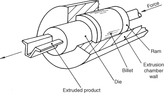
Figure 10.4 The principle of extrusion.
A billet is placed inside an extrusion press container. The exertion of pressure on the billet via a ram causes the material to pass through the die opening. This rapidly creates a long product of the required section. The outer surface of the billet is chilled on contact with the container wall and is therefore less plastic than the core where flow initially takes place. Therefore, during extrusion this outer skin containing scale and debris from the surface of the billet accumulates between the billet and the ram. This unwanted material eventually moves inwards to form a ‘piping’ defect in the last of the extruded material; this necessitates discarding the ‘butt’ end, which may be as much as 10% of the total extruded material. Metals such as aluminium, lead and tin can be extruded cold, whereas others such as steel must be extruded ‘hot’. The extrusion of plastics is very common and is described in Chapter 12. Moulding trim, tubes, rods, structural shapes and plastic or lead covered cables are typical products of extrusion.
The extrusion process is able to produce a variety of shapes of good strength, accuracy and surface finish at high production speeds. With the exception of casting no other process can provide as great a deformation or change of shape within a given time. The cost of dies is low relative to those required for casting and forging. Almost unlimited lengths of a continuous cross section can be produced from the one die and extrusion machine. For simple sections, production runs as short as 150 m can be justified due to the low die cost. Shapes that would be difficult or impossible to roll, such as hollow bars and sections with re‐entrant angles, can be extruded. However, extrusion is about three times as slow as roll forming. The main disadvantage with extrusion is that for economic production the cross section of the product must remain constant over the full length.
There are various types of extrusion. For example, in direct extrusion, shown in Figure 10.4 , the flow of metal through the die aperture is in the same direction as the ram movement, the ram being the same diameter as the container. The metal is extruded through the die until only a small amount remains in the chamber; the extrusion is then sawn off close to the die and the remains, containing the contaminants, are discarded. In indirect extrusion, the ram is hollow. A die is mounted over the bore of the ram and when force is applied the metal flows in the opposite direction of the ram movement and through the bore of the ram. Due to the reduction in friction between the billet and the container wall less force is required by this method. Two limitations of the process are that the ram is weakened and adequate support for the extrusion is difficult. Other methods include backward, impact and hydrostatic extrusion.
Review Questions
- 1 What do you understand by the terms ‘bulk’, ‘sheet’, ‘primary’ and ‘secondary’ deformation?
- 2 Discuss what is meant by the terms ‘hot’, ‘warm’ and ‘cold’ working.
- 3 Outline the advantages and disadvantages of hot and cold working in terms of processing costs and finished product quality.
- 4 Describe the rolling process used to produce steel slabs.
- 5 Briefly discuss the use of rolled products.
- 6 Why does the forging process generally allow the optimum mechanical properties of a material to be realised in a finished product?
- 7 Briefly discuss the differences between hammer and press forging.
- 8 With the aid of a sketch, describe the extrusion process.
- 9 Discuss the advantages and disadvantages of metal extrusion.
- 10 List five typical metal products that would be made by extrusion.