
4
Designing for Manufacture
4.1 Introduction
Manufacturing companies may produce products that they have designed, or they may produce them on behalf of another company that has produced their own designs. For example, mobile phones may be designed in the USA but manufactured in China. If the product designer and the manufacturer are to survive, it is essential that well‐designed products are created. Should a company's products not be designed to satisfy the needs of the consumer, then competitors' products will be purchased and the company will fail. This applies equally to domestic and export markets. Consider the contribution made by manufacturing to a nation's economy that was emphasised in Chapter 1, and that an inability of a company to sell its products leads inevitably to its demise. If this applies throughout a country's manufacturing industry it can be seen that good or bad product design can have a significant effect on the success or failure of the national economy.
Within the company, elements such as a good sales and marketing effort, tight cost controls and high productivity are useless if the design of the product is not what the customer wants. It must also be remembered that most of the cost of manufacturing a product is determined at the initial design stage: estimates of 70% in the car industry and 80% in the aerospace industry have been made. Materials and processes to be used are dictated by the product design. Therefore subsequent improvements in, for example, manufacturing efficiency, serve only to reduce the costs that have already been determined by the original design. For all of these reasons, the design process requires careful attention if a world class product is to be produced.
4.2 Computer Aided Design, Virtual Reality and Augmented Reality
Computer Aided Design (CAD) is ubiquitous; it is taught in schools, colleges and universities and is widely used by designers in every field, for example, architects, kitchen providers, artists, urban planners, landscape gardeners and of course product designers. In the case of product design, CAD is often integrated with other digital aspects of manufacturing such as computer numerical controlled (CNC) machine tools and additive manufacturing processes. Additionally, it is possible for designers of to acquire a 360° immersive experience of their CAD designs, for example, in car or ship design. This is achieved through virtual reality (VR) and can be obtained by wearing a head mounted display (HMD) or by using a very wide angle screen or multiple screens to provide an immersive environment. Also, as opposed being immersed in a design, it is possible to observe the product design within a real environment. This is done by using augmented reality (AR) and this is achieved by wearing glasses on which an image of the product design is projected. By combining this with the ability to track the wearer's head the product can be examined as to how it will look from different angles within the real world. As an alternative to glasses, the same effect can be obtained by using a mobile phone or tablet with the appropriate software. However, the focus of this short book is not on the technology of design, such as CAD, but on manufacturing – therefore, the rest of this chapter is more concerned with the basic aspects of the design process itself and how it can be applied to the design of manufactured products.
4.3 Design for X
There is a wide range of factors that need to be considered in a product design. Features such as design for safety, function, aesthetics, maintenance, repair, ease of use, environmental considerations, sustainability and manufacture and assembly, are just some of them. Thus ‘design for x’ implies a consideration of all aspects relevant to the product in question.
Different products have different design priorities. For example, fashion clothing has as its main priority aesthetic appeal; functional characteristics are less important, it is the ‘style’ that sells the product. At the other end of the spectrum we find products such as the microprocessor. Aesthetic appeal is irrelevant as the chip is not intended to be seen in use; however, functional aspects such as processing speed will be critical in determining whether or not it will be a success. In the first type of product the designer with artistic flair will have the most important input, although he or she will also require a knowledge of natural and synthetic clothing materials and how they are produced. In the second type, it is the engineering design that is important and specialist circuit designers (using CAD systems) will be required. Most products today demand consideration of a full range of attributes. For example, a motor car must be aesthetically pleasing as well as providing performance and safety.
Ecological or ‘green’ issues continue to increase in priority. Everyday examples are the use of recyclable packaging, recycled paper and minimising the use of non‐biodegradable or re‐useable plastics in products. Product designers must also remember that recycling and ‘environment friendly’ products are only a partial solution to pollution and waste. Acid rain destroying forests and buildings and industrial effluent poisoning rivers and the atmosphere can be reduced by considering manufacturing methods and their energy and environmental implications. Good product design will ensure that the manufacturing processes used will cause minimal environmental damage without recourse to the very expensive methods that treat the industrial waste after it has been produced. These solutions involve chemically or physically separating the toxic elements of the industrial waste and then if possible converting them to something useful or harmless. Long term solutions to environmental damage must rely on products being designed to produce the minimum of environmental damage as they are manufactured. Designing for re‐manufacture is also important. This is where products can be designed so that at the end of their life their individual components can be refurbished or replaced and then reassembled to the original product specification.
4.4 The Product Life Cycle
Design can be novel or incremental. Some novel designs have had important implications for society, the internal combustion engine and television being two examples. However, most design is incremental, that is each design is an improvement on what has gone before. Internal combustion engines today are much more fuel efficient and their power to weight ratios higher than that of their ancestors. Similarly the design of a modern television with a large, thin, high definition colour screen is quite a different product from the small low definition monochrome screen of the valve operated cathode ray tube (CRT) sets of the 1950s.
It is therefore apparent that the design process is not a once and for all event. If we consider each improvement as a new product then we can see that the initial and subsequent products will have a distinct lifetime. This is recognised as the Product Life Cycle and it is shown in Figure 4.1. In region A, the new product design is introduced into the market. In this area the marketing department has the major task of promoting the new product and ensuring that sales growth begins. In region B the new product is accepted by the market; it enjoys increasing demand and it experiences exponential growth. However, during this period competitors will have observed the success of the new product; this will stimulate them to produce their own competing design. In region C the product reaches maturity; it has already made its initial impact on the market, and it will probably be now competing with alternative designs by other manufacturers. In region D the sales of the product decline due to the availability of newer products possibly incorporating better technology.

Figure 4.1 The Product Life Cycle.
It is therefore important for the company that designed and built the initial product to maintain technological progress through research and development (R&D). By doing this it can stay one step ahead of its competitors' designs and ensure that it maintains its market share. Products used to have life cycles of a few years, now they are much shorter; in the electronics industry some products have a life cycle of only a few months. The beneficial effect of incremental design improvements is shown by the dotted lines in Figure 4.1 where the company introduces its new product design. Naturally, the technology alone will not ensure success; other factors such as quality, price and after sales service will also be important in creating the right package for the customer.
4.5 The Design Process
Product design and product manufacture must be considered as being concurrent: the development of the design should evolve in parallel with the knowledge of how the product will be made. Only by doing this can the company ensure that the most competitive and profitable product will be manufactured.
Traditionally, a chronological development of a design through a number of stages has been recognised. The first stage is the identification of a market ‘need’. This provides the initial idea for a product to satisfy that need. Second, a clear and unambiguous specification is created that fully describes all the attributes the product must have to satisfy the market need. Third, at the concept design stage a product concept is created, usually after having considered a number of alternatives, to satisfy the specification. Fourth, detailed design of the product is carried out. Finally, the production design stage occurs in which the design is modified to ensure the product can be manufactured economically. The problem with this traditional approach is that although it appears to follow a logical progression and each stage is an essential activity, the process becomes ‘compartmentalised’. Thus, even if an apparently optimum design is obtained at each stage, an optimum for the overall design is lost.
The practical way to ensure the best overall design is to integrate all design activities and provide an environment conducive to good communications: this requires a team effort. For example, although a mechanical engineer involved in evaluating stress – strain relationships to maximise the strength of a product may produce a functioning design, they may not be fully aware of the manufacturing processes implied. A design must not only satisfy the product design specifications (PDSs), it must also be able to be manufactured economically. The mechanical designer may also not be aware of the implications of their design for the aesthetic appeal of the product. It is therefore necessary to ensure that he or she develops the design concurrently and in collaboration with the manufacturing engineer and, if appropriate, with an Industrial Designer. An approach using a team is adopted, this team comprising representatives from the whole spectrum of manufacturing including engineering, purchasing, manufacturing and even outside suppliers of components and raw materials. The approach attempts to integrate the product design with manufacturing process design to achieve a minimum total life cycle cost for the product.
Figure 4.2 traces the design process, highlights the design goals and illustrates the information flow necessary to obtain a well‐designed product. The central spine shows the events that occur, the ‘ribs’ on either side show the information paths and the design goals that all exist concurrently.

Figure 4.2 The design process.
4.6 Identifying the Market Need
In the beginning there is usually a perceived market need. This is observed and noted by the market research group in a large company, or by an individual such as an entrepreneur or inventor. From this need or ‘market gap’ springs the idea for the product.
In a large company the idea may also emerge from a research and development group. If a company has the financial resources, and wishes to continue being a leader in its field, then it will carry out pure or ‘blue sky’ research. Should it not be large enough to fund this on its own then it may work in collaboration with other companies and organisations, such as universities and government or private research laboratories. This type of research may not have an immediately obvious commercial worth, but it is conducted in the hope of future benefits and to ensure that an innovative advantage is maintained over the competition. ‘Applied’ research has more obvious and immediate commercial applicability; it has the short‐term goal of producing a process or product suitable for immediate commercial exploitation.
4.7 The Product Design Specification
Once the basic idea of a product has been created, the next step is the formation of a product design specification, or ‘PDS’. This document must be as comprehensive and as detailed as possible. It forms the basis of all the work that is to follow, and the success of the product depends on how well it is drawn up. The specification does not state what the design is to be, but it does state the ‘boundary conditions’ within which the design must be created. Some examples of the factors that would be included in a PDS are now considered.
- Conformance to standards and specifications. Most products sold in quantity today must conform to certain standards and specifications laid down by national and international authorities. For instance, there is the International Standards Office (ISO) that has its secretariat in Geneva, in the USA there is the American National Standards Institute (ANSI) and in the UK there is the British Standards Institute (BSI).
- Product appearance. Strongly influenced by the Industrial Designer, the shape, colour, texture and general ‘style’ of the product is an important part of the specification. This will have an influence on materials and manufacturing processes to be used.
- Product performance. Depending on the product, this may take many forms. Speed of operation, number of work cycles expected in product life, intermittent or continuous working, loads to be withstood and so on are typical considerations.
- Life expectancy. There will be a certain minimum product lifetime expected by the customer and a guarantee will normally have to be given with the product. This part of the specification will state how long the product should remain in working order provided reasonable care and maintenance is provided by the customer.
- Maintenance. How frequently and easily the product is to be maintained must be specified. If the product is to be maintenance free then costs may be increased due to the need for more expensive self‐lubricating bearings and so on.
- Working environment. The conditions under which the product is likely to be used, stored and transported must be specified. The product may experience extremes of temperature, pressure and humidity. It may be subject to vibration, radiation or chemicals. It may have to operate in explosive or corrosive atmospheres. All of these factors will strongly influence the product design.
- Quantity. The total quantity of the product expected and, more importantly, the production rates and batch sizes required, should be specified. This will have implications for the types of manufacturing equipment and work organisation necessary.
- Size and weight. These factors obviously have a strong effect on the design. If the product has to be particularly small the cost may be decreased if material volume is reduced; conversely the cost may he increased if more precise manufacturing processes are demanded. Weight restriction will also influence materials to be used; this in turn will influence the manufacturing processes chosen.
- Ergonomics. This is concerned with how easy the product is to use by the targeted market. For example, the median anthropomorphic dimensions for the adult male and female population will be used when designing the driver's seating, instruments and controls in a car. This aspect is examined later in the book.
- Safety. The product must conform to all relevant safety standards within the countries where it will be sold. The specification should also state the possible abuse and misuse the product might be subjected to. Warning labels and instructions on safe operation of the product should be given, and these should be included in the PDS. It is important to remember that the designer can be held responsible for any accidents that may occur due to poor product design.
Some other factors to be included in the PDS are: likely methods of transportation; type of packaging necessary; quality and reliability expected; the time the finished product may lie around or be stored before use, that is the ‘shelf life’; cost limitations and the testing procedures that will be necessary. Consideration of the company's existing manufacturing capabilities should be made, since these will determine if the product can be made ‘in house’ or if it will be made by a sub‐contractor often in another country. This will influence cost and lead time. Also at this stage a search of existing patents, relevant literature and product data should be carried out. An analysis of competitors' products used to satisfy the same or a similar market need should be thoroughly investigated. Comparison of competitors' designs with the PDS will highlight any omissions, weaknesses or strengths of the forthcoming design. The PDS is an essential document, but it must not be immutable. Subsequent to its creation, at any part of the following design process, it should be changed should any opportunity for improvement appear.
4.8 Concept Design
The next stage is the ‘concept design’ stage, in which a design solution to the demands set by the specification is achieved. It is therefore essential that the specification exists, since it is only by using this as a datum that the adequacy of the conceptual design can be evaluated. Initially, there should be a number of alternative solutions obtained before a final selection of the ‘best’ one is made. The resulting solution should be a synthesis of all the characteristics and attributes expected of the product.
A concept design may come from an inspired individual; this does not happen very frequently and, for a large company, it is not a particularly reliable means of obtaining a steady supply of new products. Once again the importance of a synergetic team approach to design cannot be overemphasised. ‘Synergy’, in this context, is a term that implies that the effectiveness of a group of people working together is greater than the total effect of these people working individually. Teams, comprised of the individuals mentioned earlier in the chapter, can use various techniques such as ‘brainstorming’ to produce a number of possible design solutions. These will be presented for further consideration and discussion in the form of annotated drawings, textual explanations, physical 3D models and computer simulations including modelling and possibly virtual reality immersive environments.
All of the possible designs should now be critically evaluated. It may be that an aspect of one design does not exactly conform to the PDS. This design should not be discarded until the PDS has been checked to see if it should be changed to suit any advantages found in the product design. Each potential design should be fully analysed for performance and so on by carrying out all necessary calculations. This is usually done by computer to allow a speedy, efficient comparison of alternatives.
4.9 Detail Design
Following this there will be the detail design in which the individual components and sub‐assemblies will be designed. Depending on the product, detailed calculations will be carried out on, for example, mechanical, electrical or thermodynamic aspects of the design. For some products such as aircraft, motor cars, ships and some of their sub‐assemblies and components, for example engines, scale models will be made and tested and computer simulations carried out, to ensure that designs are optimised. These stages correspond to the development part of the ‘research and development’ function.
Design engineers with specialist knowledge will be involved here. Electronic circuit designers, thermodynamic engineers, mechanical stress analysts and dynamic vibration specialists are typical of the people who may be carrying out the detailed calculations and making decisions regarding the component design. Decisions affecting the details of the manufacturing process to be used will also be made here, for example, to what dimensions will the product be made, what tolerances can be allowed on the size and geometry of the components and what surface finishes are desired? In industry, around three‐quarters of the total design activity is occupied by detail design and unless the PDS and concept design stages have been properly implemented, this time may easily be wasted.
4.10 Prototyping
Once the design has been completed the first prototype of the product can be made by model makers who may use various techniques including additive manufacturing. For large products only one prototype may be made but for smaller ones a number may be produced. These prototypes will undergo testing allowing design modifications to be made before production.
4.11 Production
Finally, a number of trial production runs will be made. This is necessary as the equipment and labour used for full production is quite different from that used for prototyping. Most production usually involves unskilled or semi‐skilled labour operating special purpose and/or automated equipment. Trial production allows any last‐minute changes to tooling and methods to be made. The tooling and production methods will have been designed in concert with the product design during the earlier stages. Although changes to the product design will still be possible at this late stage, they will be expensive.
The amount of design changes and modifications necessary as the design progresses are minimised by the integrated approach previously mentioned. Figure 4.2 shows that at all stages there must be a close collaboration between all functions. Depending on the complexity of the product, various individuals will be involved in this collaboration.
4.12 Contributors to the Design
The Industrial Designer often has the responsibility of finalising the general design and appearance especially in consumer products such as kettles, irons, radios, lamps and telephones and larger products such as cars. He or she should have a good engineering background coupled with artistic training and aesthetic flair. They will have an up to date knowledge of modern materials and their characteristics, and manufacturing processes and their capabilities. He or she will be aware of design trends, have a strong sense of ‘style’ regarding the finished appearance of the product, and will be concerned about ‘ergonomics’, that is, how easy the product is to use. Specialist Engineers from appropriate disciplines will be responsible for the functional aspects of the design, for example, electronic circuit design or strength of the product. The manufacturing or production engineer will be fully conversant with the details of modern manufacturing processes and materials. He or she will know such things as the precision of each process, the surface finish that can be produced, relative process costs and their suitability for different production rates and volumes. Provided all these individuals have an input to the design process from PDS to production, the time from start to finish of the project will be reduced and the total cost will be minimised.
Concurrent with these aspects, there will also need to be an input from purchasing and planning personnel. Purchasing can provide present and anticipated costs for materials and components. Planning Engineers will be aware of the availability of company equipment and the capabilities of sub‐contractors. They will also be able to plan in advance any reorganisation necessary, plant layout changes and new tooling and machinery needed to manufacture the new design. Further comments on the need for collaboration between different roles can be seen in Chapter 5.
4.13 Some Principles of Product Design
The basic tenet here is that a good design is simple, that is, all functions of the product should be satisfied with the minimum of complexity. Following on from this guidelines have been developed that help to ensure that a product will be competitive in the market place; some of these are now considered.
- First, in general terms, the product function should be optimised. This involves getting the correct balance between all the operating factors. For example, in a car an optimum solution has to be found for each market segment regarding speed, acceleration, fuel consumption, load pulling ability and interior space. Different customers have different priorities; for example, one customer may want a sports car, another a family car capable of towing a caravan and yet another a small town car for commuting and shopping. The product must also be designed to be easy to use. Then material costs should be minimised; by selecting the appropriate material the designer can ensure that performance and manufacturability are optimal for the target market.
- Second, but no less important, the product must be ‘designed for manufacture’. The design must allow the product to be made simply. This will minimise production costs by ensuring that low cost machinery and labour are used wherever possible. For example, if only one metal component is required an additive manufacturing process may be suitable, if 20 components are to be made then machining may be acceptable, however, if the number is to be 200 000 then the product should be designed to allow a process such as die casting to be used. An additive manufacturing process such as 3D printing is only suitable for single or extremely small quantities due to its slow speed. Machining is very flexible and can be used for a range of production runs. Die casting has a higher initial cost than machining due to the special tooling necessary, but where large numbers are required the cost per part produced is much less. Also the labour required to operate the die casting machine is less skilled and hence less expensive than that for machining. These processes are explained in more detail later in the book. Some other goals are as follows:
- Keep the number of individual parts in the design to a minimum; for example, if more than one part must be used then use integral clips for joining rather than separate nuts and bolts or screws.
- Make components as similar as possible; this reduces the variety of manufacturing processes involved. Similarities may be in material (e.g. all plastic), shape, (e.g. all cylindrical or prismatic) or a specific process (e.g. shapes that can be extruded) and so on.
- Avoid redundancy, that is, do not have two parts performing the same function (unless necessary for safety, e.g. a backup braking system in a bus or a backup computer system in a manned space vehicle).
- Design for ease of assembly by allowing one component to be assembled to the next by vertical stacking movements. This also aids automation of the assembly process.
- Avoid using floppy components in a design as they are difficult to handle, especially if automated manufacturing is to be used.
- If possible, design individual components so that they can be made to a wide tolerance yet still function when assembled together; this greatly reduces manufacturing time and cost.
- Use standardisation and modularisation wherever possible. This last goal is of particular importance to today's world manufacturing environment; it is therefore dealt with more fully in the following section.
4.14 Standardisation and Modularisation
It was at the beginning of the twentieth century that Henry Ford pioneered the mass production line methods that have brought the economies of scale essential to support today's consumer society. However the original techniques restricted the design of the product, for example, 15 million of the Model Ts were produced over a period of about 18 years, but they were all virtually identical. Today, customers demand greater variety in their product and the designer has the task of trying to achieve the economies of scale typified by the Model T era, yet satisfying a wide range of requirements for discerning customers. One means of doing this is by utilising the complementary concepts of standardisation and modularisation.
- Standardisation. This is the concept of using the minimum number of parts for the maximum number of purposes while considering the or overall cost and performance of the finished product. It has the overall effect of lowering the product design cost; removing the need for special tooling, for example, drills, reamers, milling cutters and so on; eliminating research, development and planning costs and removing drawing costs. As a very rough guide, a product that has been created by using ‘off the shelf’ components from a catalogue might provide only about 90% of the performance of a product that uses specially designed components; however, it will probably also have only about 50% of the cost. In products where performance is not critical this is likely to be a decisive competitive advantage. As an example, suppose an engineer calculates, for strength purposes, that a particular product requires six 4 mm, ten 5 mm and six 6 mm diameter bolts. The concept of standardisation would say that the design should be changed so that all bolts will be 6 mm diameter. This will mean that they are all of adequate strength and that, where large numbers of products are concerned, economies of bulk buying will be achieved. Also one size of drill and tap will be used for drilling and threading the bolt holes; this will reduce storage space and stock control costs, the purchasing department will have a simplified task and material handling will be more efficient. The principle of standardisation can be applied to all aspects of product design, for example, materials, components and processes.
- Modularisation. This is the broader concept of applying standardisation to produce modularised sub‐assemblies. A car, computer or even a ship can be completely designed and assembled as a series of these modules. As well as bringing all the benefits of standardisation the concept also has other implications. For example, new modules can be designed on an individual basis to directly replace existing ones and if a number of these are introduced at the one time a new product is effectively created. Using the car as an example again – dashboards with associated instrumentation, sunroof ‘kits’ with glass and electric motors, door ‘cassettes’ containing the door shell, glass, winders, locks and stereo speakers, and seats including their frames and upholstery, are each produced as complete ready to install modules by factories specialising in their manufacture. They are delivered to the main car factory where they are assembled, often by industrial robots, to other modules on the production line. To avoid the final assembly company tying up its money in purchased modules, which also occupy valuable floor space, precise timing of delivery is important so that they arrive just as they are needed. This is called ‘just in time’ manufacture or JIT, and is discussed more fully in Chapter 23. Another implication of this is that if the module manufacturers wish to obtain maximum benefit from their investment in their manufacturing equipment then they must try to achieve economies of scale. This means that they may sell their modules to more than one end user, thus making it possible to find exactly the same modules in the products of different car manufacturers. Subsequently, end users will spend much of their design effort in making their products attractive through styling and the overall package presented to the customer.
4.15 A Design for Manufacture Example
Consider the section through the assembly design of a simplified car engine alternator as shown in Figure 4.3. This is used to illustrate a few of the design for manufacture (DFM) principles. The reader will appreciate the significance of the following exercise more fully after reading the rest of this book; however, by putting the example in here the importance of the designer having a knowledge of manufacturing processes and associated costs is highlighted. Since the alternator is a purely functional item hidden under the car bonnet no aesthetic considerations will be necessary.
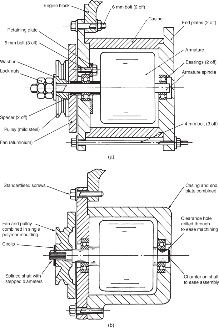
Figure 4.3 (a) Prototype design for an alternator assembly. (b) Alternator re‐designed for ease of manufacture and assembly.
Figure 4.3 a shows the original prototype design and Figure 4.3 b shows the design improved for manufacture. The following points explain the changes.
- In Figure 4.3
a the pulley and fan are separate items and are made of different metals. The pulley was machined from mild steel bar material and the fan was pressed from aluminium strip. By designing the pulley and fan as one item, as in Figure 4.3
b, to be made from one polymer moulding a number of cost savings are made.
- The costs of the mild steel bar and machining for the pulley are saved.
- The aluminium strip and presswork tooling costs for stamping out the fan are saved.
- The costs of holding separate stocks of finished pulleys and fans are reduced, as are the costs of transporting and assembling the parts since only one component is now involved.
- In Figure 4.3 b the use of lock nuts, a washer, and a threaded armature spindle to hold the pulley and fan assembly in place have been replaced by a simple circlip to retain the composite pulley/fan on a splined spindle. The pulley/fan will have a mating internal spline as part of the mould design. This system will be sufficient to prevent rotational slippage of the pulley/fan and also retain its axial position on the spindle. The new arrangement reduces the number of parts and makes assembly much quicker.
- The need for the retaining plate and associated bolts has been removed by adding stepped diameters to the shaft. As well as removing the need for four parts, assembly of the whole product is much improved since a ‘stacking’ sequence can now be followed. Previously the left hand end plate assembly would have to be completed as a ‘sub‐assembly’ before completing the final assembly of the product. Removal of the retaining plate allows the right hand section of the alternator to be used as the ‘base’ for assembly into which the other components can be stacked sequentially. This means that only one fixture needs be used to hold the work, and also that automatic assembly of the product becomes economically attractive.
- The use of stepped diameters removes the need for the two spacers, again reducing the number of parts, simplifying assembly, reducing assembly time, and lowering handling and storage costs.
- A chamfer has been added to the right hand side of the armature spindle to ease assembly.
- The right hand end plate can be combined with the casing into one casting. As well as reducing the number of parts, this type of design change also reduces the effect of tolerance build up, that is, the mating faces of the end plate and casing no longer exist therefore machining of them to within specified sizes is no longer required.
- The 4 mm nut, bolt, and washer arrangement for holding the assembly together is no longer necessary once step 6 is accepted. Thus cheaper hexagonal headed screws can be used for assembly, again reducing material and labour costs. This principle is also applied to the 6 mm bolts holding the alternator to the engine block. In practice, a check would need to be made to ensure that the clamping forces remained adequate and that vibration would not loosen the screws.
- By standardising the size of all the screws to 6 mm diameter and making the lengths the same, savings are again possible by introducing the opportunity for reduced costs due to high quantity buying, and by simplifying storage, material handling and assembly. An additional advantage to the customer is that maintenance is easier since only one size of tool is now necessary for removal and disassembly.
4.16 Conclusion
This chapter has indicated the importance of, and means of achieving, a good product design. The significance of DFM has been highlighted. It is now worth mentioning in closing a few specific historical techniques that have been developed to achieve an optimal design.
- Value Analysis was originally developed by H. Erlicher and L.D. Miles in the USA after the Second World War. It is an organised and critical approach that questions the function of each part of a product with respect to its cost. ‘Value analysis’ is the term used when examining existing products, its aim being to achieve the same performance as the original design at a lower cost without affecting the quality or reliability of the finished product. ‘Value Engineering’ is the term used when applying the technique to new products.
- DFA, or Design for Assembly, is based on work by Boothroyd and Dewhurst and aims to minimise the cost of assembly by reducing the number of parts, and then ensuring that those remaining are easy to assemble. Another method, pioneered by Genichi Taguchi, uses statistical design of experiment theory to analyse the product design.
- Finally, Professor Stuart Pugh developed an approach that aims to take into consideration the complete commercial and technical environment within which the design process is taking place. This approach is termed Total Design and Pugh defined it as ‘The systematic activity necessary, from the identification of the market/user need, to the selling of the successful product to satisfy that need – an activity that encompasses product, process, people and organisation’.
In conclusion, no matter what specific technique is used, the end result must be a product the cost of which over its whole life cycle will be such that it at least holds its own in the market place and returns an adequate profit to the company that sells it.
Review Questions
- 1 Explain why good product design is essential for the survival of a manufacturing company and why it is important economically at the national level.
- 2 What is meant by the term ‘Product Life Cycle’ and what are its implications for the product design activity?
- 3 Compare the traditional approach to product design with that of team based engineering; discuss both differences and similarities.
- 4 How might the market need for a product be identified?
- 5 Why is it so important to get the PDS correct?
- 6 Using the guidelines in Chapter 4 write a PDS for one of the following: a domestic electric food mixer; a car jack; a mobile phone.
- 7 Discuss briefly what takes place at the ‘concept’ and ‘detail’ design stages of the design exercise.
- 8 Describe the job functions that should be involved in creating a successful product for manufacture.
- 9 In general terms, name three criteria that a product designer should attempt to satisfy.
- 10 List six different criteria that should be satisfied when designing for manufacture.
- 11 Explain fully the advantages of standardisation and modularisation.