
16
Assembly and Joining
16.1 Introduction
Consider almost any manufactured product: aircraft, motor cars, televisions, computers or ships. All are really composites of a number of different elements. In previous chapters we have seen some of the means whereby the individual items and products can be produced; here, we examine the methods used to join these elements together. The joining process is usually called ‘assembly’ if mechanical fastening is being used or a number of components and ‘sub‐assemblies’ are being combined. If welding, especially fusion welding, is being used then ‘fabrication’ is normally the term applied.
This chapter looks at just some of the range of techniques for joining that are available to the manufacturing engineer. The choice of technique will depend on a variety of factors, for example, bolted joints tend to absorb vibrations better than welded joints, but a welded construction would probably be cheaper. Adhesives are becoming a popular alternative to welding and riveting as they are simple to apply, they preserve the appearance of the material and when metals are joined in this way they do not change their metallurgical properties. The choice of the joining process influences the cost of the product, aesthetic qualities and the means of repair and maintenance. Figure 16.1 is a chart showing some examples of the joining processes used in manufacturing industry; it is these that are described in the following sections.
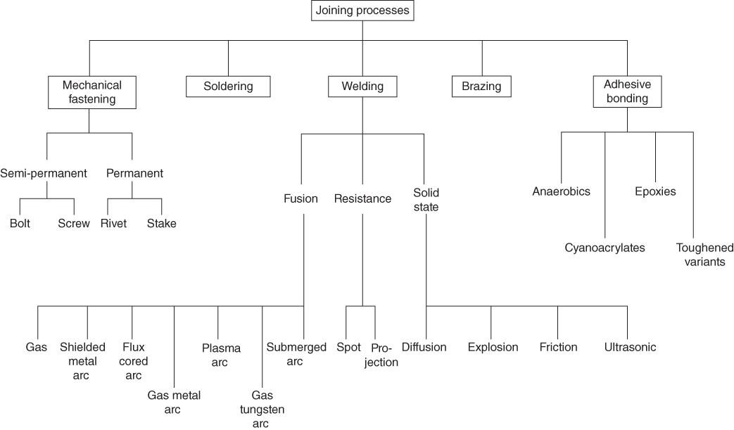
Figure 16.1 A chart showing some examples of the range of joining processes used in manufacturing industry.
16.2 Mechanical Fastening
These methods may be semi‐permanent or permanent; some examples are shown‐ in Figure 16.2. The semi‐permanent methods using screws, spring clips, nuts and bolts and so on allow easy dismantling of the assembly for repair and maintenance. For heavy duty applications bolted assemblies may be selected. For assemblies requiring medium strength and expected to be dismantled by skilled workers, cap screws with hexagonal sockets or hexagonal heads are used. A castellated nut may be used in conjunction with a split pin to prevent rotation in situations where a low tightening torque has been applied to the nut. Self‐tapping screws are used in light duty applications, often on plastics, where they make the expense of tapping the screw hole unnecessary. Self‐locking plates can be used on thin metal assemblies; they are often seen on domestic goods such as washing machines.

Figure 16.2 Mechanical fastening examples.
The permanent methods of riveting and staking are used only where dismantling of the product is thought unlikely. These methods would be used where maintenance is unnecessary and the product is to be discarded on failure. Riveting involves pushing a headed piece of metal through holes in the two materials to be joined, then spreading out the protruding metal to form the riveted head. The circular rivet hole acts as a crack arrester and therefore riveting is still popular in critical joining processes such as may be found in aerospace product manufacture. Staking is a slightly different process. Here the metal from a shaft protruding into a hole in the part to be joined is spread out against the wall of the hole using a staking punch as shown in the figure. The punch may have a chisel or star shaped point.
16.3 Soldering
Soldering is a process that uses heat, solder and flux to form a joint between two metals as shown in Figure 16.3. There are many types of solder with properties depending on their alloying elements with melting points usually between 180°C and 300°C. There are some with melting points above and below this depending on their application. Traditionally solder has been an alloy of lead and tin, the proportions varying depend on the application, for example, 37% lead and 63% tin for the electronics industry. However, today the use of lead in solder is avoided and even prohibited in some areas due to its toxicity. Lead free solders may contain metals such as tin, copper silver, antimony and others in varying proportions depending on the application. The surfaces to be joined must be cleaned and dried before soldering takes place. Heat and flux is then applied to the joint and solder. The flux further cleans the metal by dissolving oxides on the surface and preventing new oxides forming during heating; it also assists the solder to flow into the joint. The solder may be applied from a coil and an electric soldering iron or gun used to apply heat. For large volumes of electronic components mounted on printed circuit boards wave soldering is commonly used. In all applications solder joints do not provide high strength and should therefore not be used in situations where they may be subjected to heavy mechanical loads.
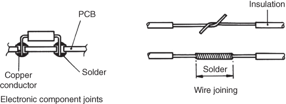
Figure 16.3 Soldering examples.
16.4 Brazing
Brazing is similar to soldering in that the metals to be joined are not heated above their melting temperature. A non‐ferrous filler material is used that has a melting temperature above 450°C. Since the parent metal is not melted the filler material must obviously be of a different composition, usually an alloy of copper, silver or aluminium. A flux, or inert atmosphere, is used to help ensure a clean joint. The filler material is drawn into the space in the joints through capillary action, thus necessitating a good close fit between the components to be brazed, see Figure 16.4. Almost all metals can be joined by brazing; less heating is required when compared to welding, therefore less distortion of the workpiece occurs and the process can be mechanised. A major disadvantage, however, is that if heated above the brazing temperature the joint may be destroyed; this limits its application to areas where high temperatures are not expected. It is a stronger joint than a soldered one, but less strong than one that is welded.

Figure 16.4 Typical brazed joints.
16.5 Welding
In welding, two materials are joined together by the use of temperature or pressure, or a combination of both. The materials are usually metal but some welding of plastics is also carried out. The descriptions that follow apply to the welding of metals unless otherwise stated. At the joint the material fuses together to form a solid structure. Figure 16.1 shows the three main weld groupings, that is, fusion, resistance and solid state.
In fusion welding the metals to be joined are brought together and heat is applied to the joint. The edges of the parent metal are often prepared by machining, thus necessitating the use of additional ‘filler’ metal. The heat melts the parent and filler material at the interface, so allowing a strong homogeneous joint to be formed. In resistance welding the passage of an electric current across the joint interface causes local heating and melting; pressure is applied at the same time and a strong joint results. In solid state welding, pressure is often used in conjunction with appropriate metallurgical conditions; the parent metal is not melted.
16.5.1 Joints and Welds
Four of the basic joints used in welding are shown in Figure 16.5, that is, butt, corner, tee and lap. There are various types of weld used to create these joints and Figure 16.5 shows the fillet and butt welds, which are the most common types. The structure and nomenclature of a fillet weld is shown in Figure 16.6. The edges of the material to be joined require no special preparation. The fusion zone, that is, the area within which the metal is melted, consists mainly of the filler metal with a little of the parent metal. Fillet welds are often used to fill a corner and are very common in structural work, for example, stiffening ribs for a ship's hull may be welded in this way.
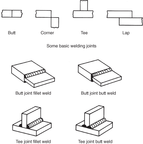
Figure 16.5 Some basic welding joints and welds.
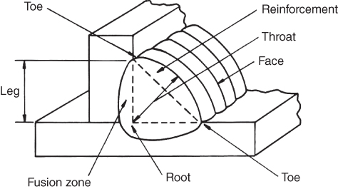
Figure 16.6 Fillet weld terminology.
A butt weld is shown in Figure 16.7. Where maximum strength is required on thicker materials, some sort of edge preparation of the parent metal is usually necessary, Figure 16.7 shows a ‘V’ preparation. This preparation is created either by the torch used in originally cutting the plate, or by machining using a single point cutting tool in a planing machine. When welding mild steel, using mild steel for the filler material, it is possible for the welded joint to be stronger than the parent metal.

Figure 16.7 Butt weld terminology.
16.5.2 Gas Welding
A number of welding processes employ the burning of a mixture of fuel gas and oxygen as the heat source for melting the joint. Additional material fed into the weld pool from a filler rod is usually necessary. Although this process can produce good quality welds there is a problem with distortion, and this prevents its widespread use in industry.
Acetylene is a common fuel gas used. An oxyacetylene welding torch is shown in Figure 16.8a. As can be seen in the sketch the oxygen and acetylene, supplied via flexible tubes from pressurised metal bottles, are combined within the handle of the torch. The resulting mixture is ignited at the tip. The ratio of fuel gas to oxygen is controlled using the flow control valves and the three types of flame that can be obtained are shown in Figure 16.8 b. Excess fuel gas produces the reducing flame that can be used to weld low carbon and some alloy steels. With equal amounts of fuel gas and oxygen, the neutral flame is produced. This is the most widely used flame as it has the least harmful effect on hot metal. The oxidising flame is produced when the proportion of oxygen is higher. This can be used to weld copper and copper alloys. Gas welding is used for welding thin metal sheets and car repairs. It can also be used for welding cast iron. The equipment is portable and relatively inexpensive.
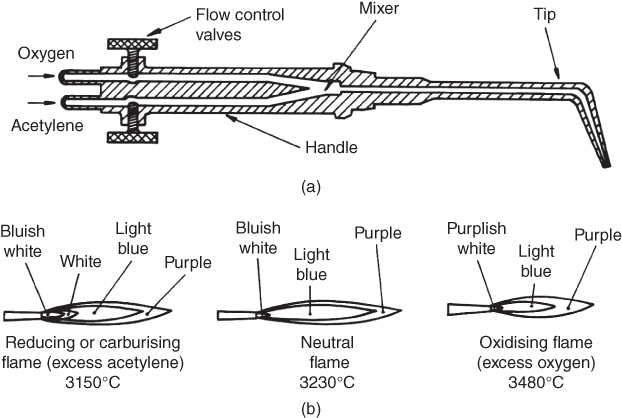
Figure 16.8 (a) Simplified section of an oxyacetylene welding torch. (b) Three types of oxyacetylene flame.
16.5.3 Shielded Metal Arc Welding
Shielded metal arc, manual metal arc or ‘stick’ welding are all different terms for the same process. Figure 16.9a shows the equipment necessary and Figure 16.9 b shows the operation of the process. Stick welding is a very common method of welding because of its portability, flexibility and wide range of applications. In the process the heat created by an electric arc struck between an electrode and the work melts the electrode tip and the parent metal. The current is of low voltage and high amperage. Molten globules of metal from the electrode are carried across the arc into the pool of molten metal at the joint. The pool follows the electrode as it is drawn along the joint, leaving behind solidified seam.

Figure 16.9 (a) Basic equipment for shielded metal arc or ‘stick’ welding. (b) The shielded metal arc process.
In this process the electrode is coated in a material which provides various functions. The electrode is often called the welding ‘rod’ or ‘stick’ and the coating ‘flux’. The flux provides; a protective atmosphere that prevents oxidation, arc stabilisation, separation of impurities from the melt, a protective slag that absorbs impurities, reduced weld spatter and alloying elements.
16.5.4 Flux Cored Arc Welding
In ‘stick’ welding the process has to be interrupted every time the electrode is consumed down to the stub. This causes the welder to lose potential production time as he replenishes his rod in the gripper. The problem could be overcome if the stick could become a length of wire that could be coiled and fed into the weld pool. This is not possible with the normal configuration as the outer coating of flux will crack when deformed. Thus the solution to the problem is to make the electrode a hollow wire containing flux internally in a powdered form. Figure 16.10 shows the principle of flux cored arc welding. It is used in similar applications to stick welding, for example, shipbuilding, general fabrication and construction work.
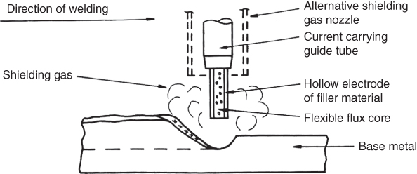
Figure 16.10 Flux cored arc welding.
The process can be self‐shielding, where the protective atmosphere comes only from the flux core compounds that generate a gaseous shield during welding, or it can use auxiliary gas shielding, where additional protection is provided by supplying a shielding gas from an external source.
The advantages of flux cored welding are that it provides a relatively high rate of metal deposition with small diameter welding wires; it can be used for a wide range of metal thicknesses from about 1.5 mm upwards; the process is simple and easy to use and it can be used in any position with the smaller diameter wires, for example, for overhead welding. One disadvantage with the process is that a considerable amount of welding fumes are emitted during operation. This means that additional equipment has to be provided for drawing off the fumes, especially when welding indoors.
16.5.5 Gas Metal Arc Welding
Another name for this is Metal Inert Gas or ‘MIG’, welding. The process is shown in Figure 16.11. A bare continuous wire electrode is fed through the welding torch from a coil. The torch is water cooled. An inert gas is fed down the annulus of the torch to form a cloud around the arc and weld pool that protects the weld from atmospheric contamination. The gas is often carbon dioxide though other gases can be used. The process provides relatively high deposition rates. The fact that the wire can be fed, and the process monitored, automatically means that it is suitable for use in conjunction with industrial robots. In fact robotic arc welding is now one of the most popular applications for robots.
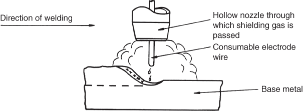
Figure 16.11 Gas metal arc welding.
16.5.6 Gas Tungsten Arc Welding
Tungsten inert gas and ‘TIG’ welding are alternative names for this process. It is similar to MIG welding except that a non‐consumable electrode is used, a hand fed filler rod usually being necessary to supply additional metal to the weld pool. The inert gas in this case is usually Argon or Helium. The process is shown in Figure 16.12. It can be used for welding a wide range of often difficult to weld materials such as cast iron, aluminium alloy, magnesium, titanium, stainless steels and so on. The process is ideal for welding thinner sheets of metal under 1 mm thick.

Figure 16.12 Gas tungsten arc welding.
16.5.7 Plasma Arc Welding
Deep and narrow welds in most metals, usually less than 6 mm thick, can be produced by this process. Gas is heated to an extremely high temperature by an electric arc, then forced across to the weld area. The arc temperature can reach 33 000°C and the gas is ionised, that is, it becomes a plasma. The two methods of using this process are shown in Figure 16.13a,b. In Figure 16.13 a the arc is transferred across from the electrode to the workpiece, in Figure 16.13 b the arc occurs between the electrode and the nozzle, and it is the plasma gas alone that carries the heat across to the joint; this latter method is easier to control though slightly more expensive. Just as in MIG and TIG, an inert shielding gas is also provided. High welding speeds, narrow heat affected zones and reduced distortion are some advantages of this process. A disadvantage is that it can create considerable noise and fumes. This means that measures have to be taken to ensure a safe working environment for the welder and other people in the area.
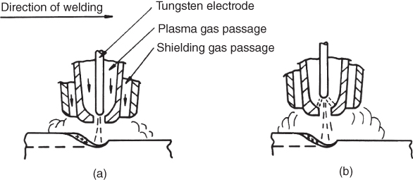
Figure 16.13 Plasma arc welding: (a) transferred and (b) nontransferred.
16.5.8 Submerged Arc Welding
Operating in a similar manner to stick welding this process can be applied to much thicker materials. The joining of steel plates for ships' hulls is a typical example. The main differences in the process are that the electrode is continuous, the flux is supplied in a powder form through a dispensing tube and the path of the arc is within the molten flux so preventing contamination from the atmosphere. Figure 16.14 shows the principle. The process is often carried out automatically; the welding head is suspended from a gantry as it traverses the joint. Rate of welding, feed rate of the electrode wire and flow of flux are all controlled automatically. The welds produced are usually of high quality. A large metal deposition rate is possible but stronger joints are created if a number of smaller welding runs are made rather than a single large one.
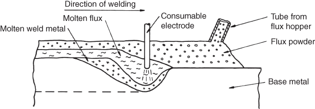
Figure 16.14 Submerged arc welding.
16.5.9 Resistance Welding
The previous welding techniques were all fusion types in that the parent metals were melted along the joint. In resistance welding the flow of an electric current across the interface between the two metals to be joined creates the heat necessary for a localised coalescence. The metals to be joined are almost always thin sheet steel.
In resistance spot welding, shown in Figure 16.15, the two overlapping pieces of metal to be welded are placed between two water cooled copper electrodes. The system is constructed so that one of the electrodes can be held steady while the other can exert downward pressure onto the joint, as shown in the figure. The pressure at the point of contact is high, as the moving electrode is actuated by a powerful pneumatic or hydraulic cylinder and the surface area of both electrodes is reduced at the point of contact. The combination of carefully controlled pressure and current flow causes the formation of a weld nugget at a spot between the electrodes at the interface of the metals to be joined. The equipment necessary for carrying out this type of welding is not usually very portable. A very common application is in motor car assembly, where the spot welding guns are often wielded by large industrial robots. Almost all joints on the body of a car are spot welded.

Figure 16.15 Resistance spot welding.
In resistance projection welding a weld nugget is again created at the interface between the metals to be joined. Again it is made by a combination of pressure and resistance heating from the flow of current across the interface. However, in this case the small contact area across which the current flows is created by forming projections on one of the metal sheets to be joined. The principle is shown in Figure 16.16. The equipment is often mounted on a pedestal similar to some used in spot welding. The electrodes in projection welding are wide and flat, whereas those used in spot welding are narrow, with a small contact area. Strip and sheet metal components and wire mesh products such as supermarket trolleys are welded in this way as the small contact areas at the intersection of wires constitute projections.
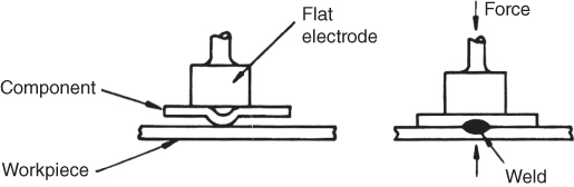
Figure 16.16 Resistance projection welding.
16.5.10 Solid State Welding
In solid state welding the material to be joined is not melted directly by an external heat source. For example, in the fusion welding processes only heat was added to form a joint, in the resistance welding methods heat and pressure were used to create a joint. Now, in solid state welding, we consider some of the welds that can be created by using pressure and sometimes heat, but without raising the temperature of the metal above its melting point.
Diffusion welding is used mainly for joining dissimilar or relatively expensive metals. Components for military aircraft using the advanced materials, such as superalloys, can be fabricated in this way. The process involves careful cleaning and preparation of the contacting faces of the parts to be joined. The parts are then placed against each other and pressure is applied for a considerable length of time. Heat is also applied by carrying out the process in an oven; the temperature may be about half of the melting temperature of the material. During the process the weld is formed by the migration of atoms across the boundary at the interface between the two metals. This means that the process is slow and hence relatively expensive.
Explosive welding is used mainly for cladding, that is, joining sheets of metals with one type of property to those of another. For example, armour plating or thin sheets of corrosion resistant material can be bonded to softer and cheaper structural plates of (say) mild steel in this way. The process is shown in Figure 16.17. An explosive charge is placed on top of the metals to be joined. The charge is usually of sheet form and is progressively detonated from one end. On detonation a stress wave is formed that compresses the metal sheets together as it travels along the length of material to be joined. The kinetic energy in the pressure wave is so intense that mechanical bonding takes place between the metals. The process is of course dangerous and must be carried out under carefully controlled conditions.

Figure 16.17 Explosive welding.
Friction welding is used for the rapid joining of two components where at least one has rotational symmetry. It also produces strong joints between dissimilar metals. The process is shown in Figure 16.18. One of the components to be joined is held in a chuck and rotated at high speed. The other component is then brought into contact with the spinning piece and an axial force applied. The friction created generates heat sufficient to cause fusion of the two metals at the area of contact. Typical applications of the process are; joining of motor car transmission shaft elements, joining of bolt heads to bolt shanks and construction of engine valves.

Figure 16.18 Friction welding.
Ultrasonic welding is used for joining thin sheets, foil and wire of similar or dissimilar materials, and it is also used for joining plastics. The process is shown in Figure 16.19. The workpiece is subjected to a downward static force from the mass shown. It is also subjected to an oscillating lateral movement generated by the vibrating transducer that operates at several kHz. The combination of movement and force at the interface of the materials creates a temperature of up to half the material melting point and breaks up any layers of oxides or contaminants. Thus, the combination of pressure and temperature allows the creation of a very strong bond.
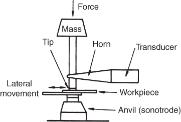
Figure 16.19 Ultrasonic welding.
There are many other welding processes, but those that have been shown here should be adequate to convey an idea of the variety of applications.
16.6 Adhesive Bonding
Although adhesives have been in use for decades, recent advances in their design have led to a wide range of adhesive types, and consequently a wide range of applications. Adhesive bonding has many advantages over other joining techniques. For example, the load at the joint interface can be distributed over a large area, reducing stresses in the joint. Adhesives are lightweight. Completely dissimilar materials can be joined together. The structure of the materials being joined is not disturbed in any way by having holes drilled for mechanical fastening or being melted during welding. Thin, fragile or porous materials can be easily joined. As the temperatures at which bonding takes place are relatively low, no distortion or, if metal, damaging metallurgical effects happen to the material. Adhesives are inexpensive when compared to other joining methods. Products joined by adhesives generally look better than those that have been welded or mechanically fastened. The disadvantages are that the adhesive will fail if subjected to too high a temperature; surface preparation of the materials to be joined is critical, therefore this part of the process can be time consuming; the time to cure the joint may also be long and finally, some adhesives are unpleasant or dangerous to work with in an enclosed area.
16.6.1 Joint Loading and Design
Figure 16.20a shows the loading conditions that may be experienced by an adhesive joint and in Figure 16.20 b examples of different types of joint. As can be seen, adhesive joints that are subjected to compression loads have the best strength, those in tension and shear are acceptable, but those in cleavage or peel have poor strength. Therefore, when designing a product adhesive joints should be positioned so that they experience compressive forces and tension or shear if necessary, but cleavage and peel conditions should be avoided. The joint design itself should be such that as large a surface area of adhesive as possible is employed. Mechanical strengthening also helps, for example, the use of a glued dowel adds considerable strength.

Figure 16.20 Adhesive bonding. (a) Adhesive joint loading conditions and (b) designing adhesive joints.
16.6.2 Adhesive Types
A wide variety of adhesive types exist, each one designed to be suitable for certain applications and materials. Four types are briefly noted here as typical examples.
Anaerobic adhesives are used for making gaskets, thread locking on bolted or screwed components, pipe sealing and so on. They are widely known as ‘sealants’ or ‘locking compounds’. They increase the strength of mechanical joints, which should be close fitting as the adhesive cures in the presence of metal and the absence of air.
Cyanoacrylates are used for the assembly of plastic and electronic components. They cure through reaction with moisture present on the surfaces of the materials being joined. Close fitting joints are necessary, but curing speed may be measured in seconds and a high strength joint is obtainable.
Epoxies are used for large joints and in tough applications such as the bonding of carbide tool tips. They are versatile and give strong hard joints with most materials. They are often in two parts, that is, an epoxy resin and a hardener, which when mixed together produce the adhesive.
Toughened variants are used in critical applications such as in aircraft construction. The anaerobics and cyanoacrylates are acrylic based, the epoxies are obviously epoxy based and the toughened variants are acrylic and epoxy based. A rubber material is incorporated in the toughened variant material to provide high peel strength and shock resistance. They also have a fast cure rate.
This chapter has shown the most popular methods of joining materials together to form sub‐assemblies, assemblies or complete products. The choice of the most suitable method for a particular task should take into account the aesthetics of the product, its functional performance and the manufacturing processes available. This again illustrates the need for a team approach to decision making, the selection of the joining method possibly relying on input from, for example, an industrial designer, a mechanical engineer and a manufacturing engineer.
Review Questions
- 1 Briefly list the five main categories of joining processes used in manufacturing, and state the general type of application to which each is suited.
- 2 What is ‘welding’ and what conditions are necessary for it to occur?
- 3 What is the difference between a fillet weld and a butt weld, and under what conditions would each be used?
- 4 Describe the welding process that is most likely to be used for making minor repairs to the sheet metal body of a car.
- 5 Why is ‘stick’ welding so widely used?
- 6 What advantage is gained by putting the flux in the core of the electrode in shielded metal arc welding?
- 7 What is gas metal arc welding and why has it become so popular for automated welding installations?
- 8 Describe an arc welding process suitable for welding cast iron or aluminium alloy.
- 9 What are the advantages of the plasma arc welding process? Name one disadvantage.
- 10 Describe the process you would choose for welding together thick steel plates such as those used for ships' hulls.
- 11 Describe the welding process widely used in the car industry for fabricating car bodies.
- 12 What do diffusion, explosive, friction and ultrasonic welding have in common? Name one application for each.
- 13 Why has adhesive bonding become popular as a joining process?
- 14 Name one type of adhesive and a typical application.
- 15 Are joining processes necessary? What can be done to eliminate them?