
19
The Building Blocks of Automated Systems
In this chapter, we will consider some of the components commonly found in automated manufacturing systems. These examples show how actuation of these systems can be obtained, how control of movements can be effected and how information on the system can be fed back to the controllers.
19.1 Cams
A purely mechanical component cams are probably one of the earliest control devices; these are used to control the movements of cam followers, which are in turn connected to linkages. These linkages are used to move cutting tools, pick and place devices, inspection probes and so on. Three types of cam are shown in Figure 19.1. The cam profile is machined around the perimeter or into the surface of the cam, which is usually made of steel, and it is the profile of the rotating cam that determines the movement of the follower. Cams may still be found in hard automation such as screwcutting machines where the product is produced in high volumes and is unlikely to change over a period of years. However, where product volume is not so high and product changes are more frequent, then it is easier and cheaper to control movements by microprocessor‐based programmable systems.
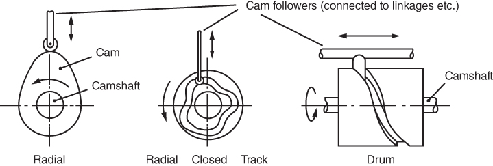
Figure 19.1 Three types of cam used in dedicated ‘hard’ automation.
19.2 Geneva Mechanism
Another mechanical device this is used to produce a rotary indexing movement in, for example, a worktable or toolhead of a turret lathe in a hard automation system. Its principle of operation is shown in Figure 19.2. The slotted Geneva plate has equispaced radial slots. An indexing plate has a fixed pin which engages with the slots as it rotates. Since the Geneva plate shown has six slots (other numbers of slots could be used), one revolution of the indexing plate will cause the Geneva plate to rotate one sixth of a revolution, that is, 60°. After each index the locking plunger will hold the mechanism in position until the rotating pin engages again. The number of steps per revolution is therefore determined by the number of slots in the Geneva plate.
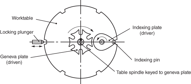
Figure 19.2 A Geneva mechanism.
19.3 Transfer Systems
Transfer of parts between workstations in an automated system is effected by rotary or linear transfer machines and linear transfer lines. The workstations themselves may involve machining, handling, assembly or inspection operations. Linear systems can be used for any number of workstations, but rotary machines are limited to applications where only a small number of operations are involved. The heads of these systems are constructed from basic elements, for example, pneumatic and hydraulic actuators with grippers or inspection probes attached, or cutting tools driven by electric motors. The rotary or linear movement of the parts can be effected by a variety of means such as the Geneva indexing mechanism for rotary machines or the pawl type linear transfer system. A pawl system is used to produce a linear indexing movement and the principle of operation is shown in Figure 19.3. Reciprocation of the transfer bar can be effected by a pneumatic or hydraulic piston or via an electric drive. Since the movement is equal to the spacing of the workheads, the work carriers will be indexed the desired distance along the line with reciprocation. This type of transfer system may be found in various applications, one example being the transfer of large sheet steel car components through presswork operations in automobile manufacture.
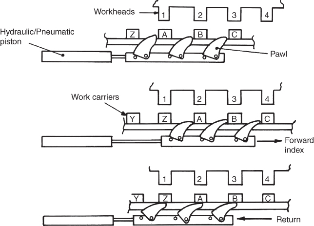
Figure 19.3 A linear transfer system.
These configurations are often found in hard automation systems, where each workstation has been specially designed to carry out one operation before the parts are passed on to the next station in ‘line’. They are therefore ‘dedicated’ machines, since they would need to be completely dismantled and rebuilt for a change in product.
Linear transfer lines, such as those used for car assembly, are not as inflexible as a purpose built linear transfer machine used for, say, machining engine blocks. These lines have workstations located along their length that use a variety of dedicated equipment such as surface treatment plant, reprogrammable equipment such as spot welding robots and human labour used for work that is impractical to automate.
19.4 Conveyors
These come in many forms. For example, roller conveyors are popular for transporting individual units such as boxes or components; the rollers may be powered by electric motors or free running. For bulk material, small components and foodstuffs, powered belt conveyors are often used. A roller conveyor system is shown in Figure 19.4.
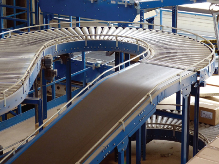
Figure 19.4 Conveyor system. Source: Reproduced with permission of Pixabay.
19.5 Limit Switches
These are simple electromechanical devices found in almost all automatic systems. They are made in various configurations and three are shown in Figure 19.5. They incorporate a small micro‐switch operated by a mechanical plunger. This plunger is caused to move by a variety of means depending on the application. When the switch is operated it sends an electrical signal to the system controller to initiate some action. These switches are used in many applications, for example to limit the travel of a handling device, sense the presence of components on a conveyor line or detect the opening of a safety barrier.
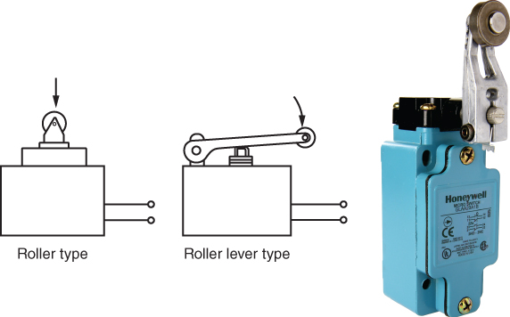
Figure 19.5 Some limit switch configurations.
Source: Image courtesy of Honeywell.
19.6 Fluid Power Components
Pneumatic and hydraulic systems use the fluids of air and hydraulic ‘oil’, respectively. Pneumatic devices that use compressed air at a pressure of between 1 and 7 kilopascals (kPa) and hydraulic devices that use fluid pressurised to between 70 and 170 kPa are used to drive many automatic systems; for example, hydraulic or pneumatic actuators would be used to operate the pawl mechanism mentioned earlier. Hydraulics are useful where very high loads have to be moved or sudden shock loads are experienced, but due to the problems associated with the high pressures and the possibility of leakages hydraulic machines are now less common in manufacturing systems. Pneumatics, however, are very popular. These devices are cheap, fast, clean, safe and easy to work with. Almost all factories have an air compressor and compressed air system installed (they are also found outside industry for powering ‘animatronic’ tableaus of characters and dinosaurs etc.).
Pneumatic and hydraulic devices work on the same principle, a pressurised fluid is forced through connecting tubes to an actuator that does the work. The fluid is pressurised by a compressor in the case of air and a pump in the case of hydraulics. The flow of the fluid is controlled in both cases by valves. In automatic systems these valves incorporate electromagnets called solenoids that allow the valves to be opened or closed by electrical signals from a controller. With hydraulic systems much more complex control of speeds and forces can be obtained by using servo‐valves that regulate the flow of fluid based on instructions from an electronic control system. The reason hydraulics allow better control is that hydraulic fluid is incompressible while air is not; this means that pneumatic actuators are used for simple movements where the load or actuator can be pushed against a fixed stop. A sketch of some pneumatic components is shown in Figure 19.6 and a simple system is shown in Figure 19.7. The control valve in Figure 19.7 is shown according to a convention that indicates symbolically the two possible positions of the valve that allows air to flow into or out of the pneumatic cylinder.
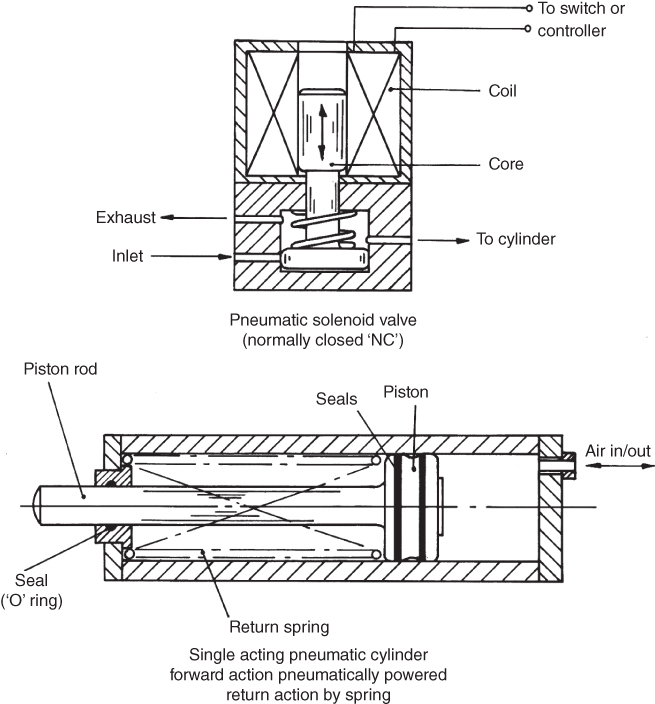
Figure 19.6 Simple pneumatic control valve and piston.
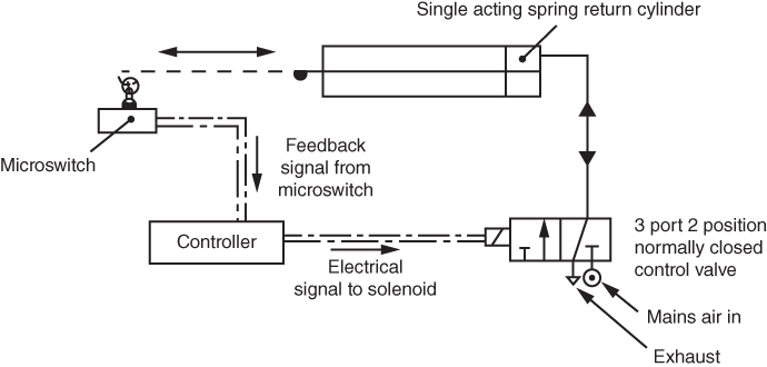
Figure 19.7 Simple pneumatic circuit.
19.7 Electric Motors for Actuation
For complex control of automated machines, such as numerically controlled machine tools or industrial robots, special electric motors are used. These are called servomotors because they incorporate some sort of ‘feedback’ device that sends a signal back to the controller indicating the actual response of the motor to a command signal. Two types of servomotors are common, that is, the permanent magnet (PM) direct current (DC) motor and the brushless motor. Electric motors operate on the principle of passing an electric current through conductors in a magnetic field and so producing a torque. In servo‐motors the magnetic field is produced by the permanent magnets and the conductors are created by the motor coils; schematic sections of them are shown in Figure 19.8.

Figure 19.8 Typical electric servomotors used in manufacturing automation.
The PM DC motor has been the most common due to relatively simple control; however, brushless motors are now popular as the cost of their control has decreased. Brushless motors do not have carbon brushes to wear and so replacement costs and downtime due to maintenance are reduced; they also dissipate heat better and are simpler in construction. These motors are usually controlled by a method called ‘pulse width modulation’; this allows control of the current passed to the motor coils thus controlling the motor torque and hence the speed of rotation.
For moving very light loads non‐servoed stepper motors are used; these do not need feedback devices. They ‘step’ round one increment, say 1.8°, for every pulse received from the motor controller. Thus if the controller counts the number of pulses sent to the motor the angle of the motor shaft will be known at any point in time; also by monitoring the rate at which the pulses are sent it can calculate the speed of the motor.
19.8 Feedback Devices
These devices, used widely in soft automation systems, provide feedback information on displacement and speed to the controller. There is a wide range of types; we will consider just three here: the potentiometer and the tachogenerator, both analogue devices, and the digital optical shaft encoder. Analogue devices produce an infinitely variable signal proportionate to the quantity being measured, whereas digital devices produce a series of discrete pulses whose rate or pattern provides the necessary control information.
A potentiometer is used to provide information on angular displacement. It is essentially a calibrated rotary variable resistor, its principle of operation being shown in Figure 19.9. A direct current supply of volts (V) is applied across a resistance R. The output voltage is measured by tapping over a distance, r. The distance, r, and hence the output voltage, v, will vary depending on the angular displacement of the wiper arm as it rotates about the central shaft thus the voltage, v, indicates the angle of rotation. The shaft is usually attached to the part of the automatic device whose movement is being measured.

Figure 19.9 The potentiometer, an analogue device for displacement measurement.
A tachogenerator operates as a motor in reverse, that is, it generates a current when its coils are rotated in a magnetic field when made integral with a motor by mounting it on the same shaft. The location of the tachogenerator on a motor was shown in Figure 19.8 , it produces a voltage signal proportionate to the speed of rotation, see Figure 19.10. One disadvantage of the tachogenerator is the small dead spot in the middle of the graph where there is a poor response to low speeds.

Figure 19.10 The tachogenerator, an analogue device for measuring rotational speed.
The optical shaft encoder is a very popular means of obtaining feedback information on angular displacement. Its principle of operation is shown in Figure 19.11. It is composed of a glass disc that may be transparent with opaque sections or opaque with transparent apertures. The disc is mounted on a shaft, for example, the shaft of an electric brushless motor or a joint on an industrial robot. An array of LEDs (light emitting diodes) is located on one side of the disc while an array of light sensitive sensors is located on the other. These photosensors produce a voltage when exposed to light. As the sections or apertures pass the light sources so the sensors register the pulses of light by creating corresponding voltage pulses that are sent to the controller. Since the pattern of sections or apertures is known, for example, say 360 apertures per revolution, by counting the number of pulses the angle of the shaft will be known. By noting the number of pulses per second, the speed of the shaft will be known and by noting the change in speed with respect to time, the acceleration or deceleration of the shaft can be determined.

Figure 19.11 The optical shaft encoder, a digital device for displacement measurement.
A microprocessor‐based controller is usually used with these devices. Shaft encoders are of two types, the incremental encoder and the absolute encoder. The incremental type simply sends a train of pulses to the controller; this means that if power is removed from the system, even for a short time, then the encoder will not know where it is in absolute terms when power is restored. Therefore, when they are used for example on industrial robots, the robot has to be taken to a ‘home’ or reference point every time power is restored to it. Absolute encoders do not have this problem; they have a coded pattern of sections or apertures that uniquely defines the angular displacement of the disc. Thus if power is lost then restored, the unique pattern of signals from the photocell array will inform the controller of the exact position of the shaft.
19.9 The Vibratory Bowl Feeder
This is the most popular part holding and feeding device for automated systems, being found in almost every factory engaged in automated assembly work. Its construction is shown in Figure 19.12. It basically comprises a cylindrical bowl with a slightly convex base and a helical track running from the base of the bowl up around the internal wall to the rim, where it meets a delivery chute. The bowl is supported on three leaf springs inclined at an angle; these springs are fixed to a heavy base. Between the bowl and the base is a powerful electromagnet. In operation, the bowl is partially filled with the parts that are to be fed. When power is supplied the electromagnet is switched on and off at high frequency. During each instant that the magnet is on it pulls the bowl downwards in a twisting action caused by the inclined springs. Thus as the bowl vibrates at high frequency the parts in the bowl are shaken down the convex base to the bowl wall, where some will rest on the helical track. The high frequency vibratory twisting action causes the parts on the track to be left momentarily suspended in air; they then drop down onto the surface of the track at a point slightly ahead of where they left it. In this way, the parts move up the track to the delivery chute. Once they reach the chute they slide down to the work station under the force of gravity. Careful design of the bowl track can ensure that only parts at the desired orientation are fed to the delivery chute, see Figure 19.13 for an example.
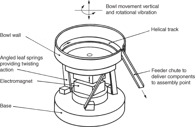
Figure 19.12 A vibratory bowl feeder.

Figure 19.13 An example of bowl feeder track design.
19.10 Programmable Logic Controllers (PLCs)
Programmable logic controllers (PLCs) are microprocessor‐based and are used across a wide range of applications both within and without industry. They can have digital and analogue inputs and outputs and can carry out sequencing, timing, logic and calculations. In the manufacturing context they are used to control and monitor equipment and processes and are designed for ease of interfacing and to withstand the rigours of the industrial environment. Both dedicated and reprogrammable automated systems are often connected to PLCs to enable interfacing with sensors and safety equipment. Figure 19.14 shows the basic elements of a PLC and a typical physical configuration although their form can vary widely. The Central Processing Unit or CPU is capable of carrying out all of the decision making, logic and mathematical functions, and also supervision of all the input and output signal. The memory contains the instructions as to how the PLC is to control the external equipment. The low voltage power supply provides power to the controller and for the output signals. A program input device is also required, for example, a keyboard or touchpad.

Figure 19.14 A programmable logic controller (PLC) elements are shown on the left and a basic PLC is shown on the right.
Source: Image courtesy of Siemens.
19.11 Control of Automated Machines
Finally, a brief discussion on how automatic control is obtained on an automated machine or system. The factors that usually need to be controlled are: the sequence of movements, the speed of movement and, in some cases, the path followed by the mechanism. The control of the sequence of movements can be obtained by sending trigger signals from a microprocessor system, such as a computer or a PLC, to the control valves or motors of the machine. However, speed and path control is more complex and usually involves control of electric current to a motor for electrically powered systems or to a valve that subsequently regulates the flow of fluid in systems that are fluid powered. Terms that are used in describing control systems include: open loop, closed loop, feedback and servo‐control.
- Open‐loop control is the type of control found, for example, on cam operated machines or machines under computer control that are subjected to small loads. In this type of control, the machine is expected to operate exactly as commanded by the system controller and no automatic verification is made. This can be used only where light loads are involved and there is a high degree of confidence that the desired action will take place.
- Closed‐loop control is the type used in almost all computer or microprocessor‐controlled machines. It is found in numerical controlled machine tools, industrial robots and automated guided vehicles; outside the factory it is found in such things as advanced SLR cameras, car fuel management systems and aircraft autopilots. All of these artefacts have a common attribute – they are ‘mechatronic’ devices. A mechatronic device is one that is composed of mechanical, electrical and electronic elements under the control of a microprocessor.
- Implicit in the term ‘closed‐loop control’ is the concept of feedback this signifies that a signal is sent back from the device being controlled to the controller. This signal contains information on how the device is responding to the controller's commands; the controller can then use this information to modify its commands to ensure that the device performs as required. For example, assume that the controller sends a signal to an amplifier to send a specific current to an electric motor that should cause the motor to rotate at a desired speed. The feedback device on the motor, for example, a shaft encoder, sends a signal back to the controller that the motor is moving too slowly. The controller will then modify its output signal to cause the current to the motor to be increased.
- This type of control is often called servo‐control. Essentially, servo‐control implies a system that involves amplification of a control signal, for example, the braking system in a car where the manual force applied to the brake pedal is amplified by the brake servo‐system to produce a larger force at the brake pads. In the types of machines we are concerned with, this type of control is always present since the low power command signal is usually a low voltage signal from the controller. However, in industrial applications servo‐control is usually synonymous with feedback and closed‐loop control.
Review Questions
- 1 Describe with the aid of a sketch the operation of purely mechanical automation device, the purpose of the device should also be stated.
- 2 What is a ‘limit switch’ and where might it be found?
- 3 Provide a sketch of a simple pneumatic circuit.
- 4 What is a servomotor and what advantages does the brushless type have over the more traditional brushed motor?
- 5 Describe an analogue device for measuring displacement and an analogue device for measuring speed.
- 6 Describe a digital device for measuring rotational displacement and state how this can be used to also provide speed and acceleration information.
- 7 State the purpose of a vibratory bowl feeder and provide a brief description of its operation.
- 8 Briefly discuss the elements of a PLC and give an example of its application.
- 9 Explain the terms open‐loop and closed‐loop control.