
6
Materials for Manufacture
6.1 Introduction
A design and manufacturing engineer must have a good knowledge of the types and properties of materials from which a product can be manufactured. The material must not be so expensive as to make the product uncompetitive in the market place, yet it must possess all the characteristics necessary for the functioning of the product. Factors such as cost, strength, hardness and how easily it can be worked must be considered carefully by the designer. Although there is already a wide range of materials available, research and development ensure that new ones are constantly being created. In plastics alone it is estimated that hundreds of new variants are developed each year. Advances in various areas of technology can often stimulate the need for new materials. For example, the possibility of building spacecraft created a requirement for materials, including metals, which could withstand extremes of temperature, pressure and vibration.
We will mainly concern ourselves with metals and polymers that are the most common engineering materials. Other materials, such as composites and ceramics, are also noted. These materials are gaining in importance as more is learned about how to manipulate their structures to obtain desired properties.
One way of grouping materials is shown in Figure 6.1, that is, into metals and non‐metals. Metals are essentially chemical elements, such as iron, copper, gold and aluminium, or alloys of elements, such as steel and bronze. They are often lustrous when smoothed or polished, are usually good conductors of electricity and heat and are likely to have a good strength to weight ratio. They can be further classified into the iron‐based metals, that is, the ferrous and non‐ferrous metals. The ferrous metals include the steels widely used in the construction of a broad range of products from pins and paper clips, through to motor cars, ships and bridges. The non‐ferrous materials are also used in a variety of familiar applications, for example, electrical wiring made from copper and strong light‐weight aircraft components from aluminium.
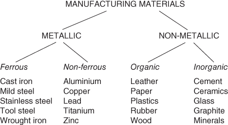
Figure 6.1 A simple materials classification.
The non‐metallic materials can be split into organic and inorganic materials. Originally the organic materials were only those that had their origin in living organisms, for example, wood and leather. Now organic materials are regarded as those based on carbon compounds generally, though it is interesting that the basic ingredients for even the synthetic polymers or ‘plastics’ are obtained from oil, natural gas or coal, which in turn come from long‐dead living matter. The inorganic materials come originally from the earth in the form of minerals. In the past they were used more in the construction industry than in manufacturing, but developments in ceramics and cements are producing many new manufactured products.
Where strength at relatively low cost is required metals are still by far the most common material used. Other materials, especially the plastics, are steadily gaining in ground in properties and popularity. For instance, it is claimed that the volume of plastics sold is now greater than that of metals. Very approximately, as the percentages can vary, a typical family car will be comprised of over 75% metals and around 15% plastics with the remainder made up of rubber, glass, leather/fabric, ceramics and fuel, oil, coolant and so on. The metals will mostly be steel used in the body of the car, with cast iron or aluminium alloy used in the engine block, lead in the battery and copper for the wiring. More expensive cars will have aluminium used in the body and the most expensive may have carbon fibre bodies for very high strength to weight ratios. However, the predominant material in manufactured products where strength at relatively low cost is required remains metal, and in particular steel, in the form of various alloys. We will now therefore consider how metals are structured as this is necessary for an understanding of how they can be manipulated to manufacture products.
6.2 The Structure of Metals
6.2.1 Atomic Bonding
At this fundamental level we find that there are two ways in which atoms can be held together, that is, primary and secondary bonding. Secondary bonding is a weak bonding, which is not necessary to consider here. The primary bonding is important as it is strong. Primary bonding has three types: (i) the ionic bond in which electron transfer occurs, (ii) the covalent bond in which electrons are shared and (iii) the metallic bond in which there is a structure of positive ions surrounded by universally shared wandering electrons. These electrons provide metals with their relatively high thermal and electrical conductivity. The structure can be deformed without the bonds breaking; this allows metallic bond materials to be changed in shape yet retain their original strength. The metallic bond is therefore of most relevance here; the covalent and ionic bonds will be mentioned later when ceramics are discussed.
6.2.2 Atomic Arrangement
This tells us how the atoms arrange themselves in a material. There are three types of structure: (i) molecular as in water, (ii) amorphous as in glass and (iii) crystal as in metals and most minerals. In crystal structures the atoms are arranged in a regular geometric array known as a space lattice. When metals solidify by cooling they adopt a crystalline structure and the atoms group themselves into one of these lattices. The three main types of lattice are body centred cubic (BCC), face centred cubic (FCC) and hexagonal close packed (HCP), see Figure 6.2. This structure helps determine how easily the material can be worked or deformed, for example, FCC metals can usually be easily deformed without fracturing, whereas HCP metals are difficult to work.
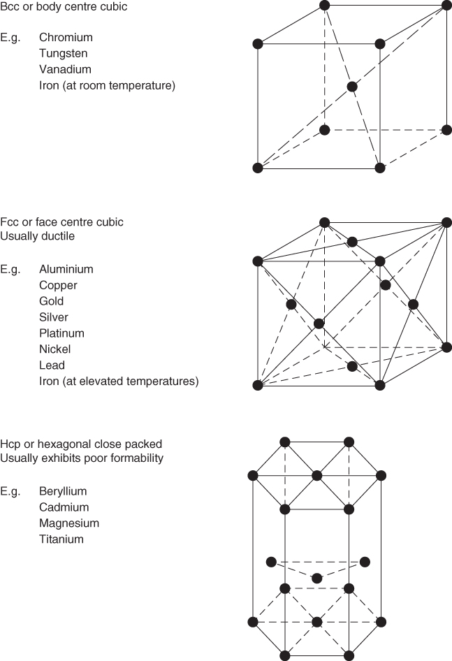
Figure 6.2 Three main types of crystal structure.
6.2.3 Grain Formation
As described before, when a metal solidifies atoms arrange themselves geometrically to form a crystalline structure. The initial lattices that appear become the nuclei or seeds from which the crystals of metal will grow. Many of these nuclei form in the initial stages of solidification but the direction in which each lies is random. As the crystals grow, the lattice pattern of the source seed is maintained as successive lattices align themselves with their predecessors. Eventually, when one growing crystal comes into contact with another of different orientation, growth of both will stop. The surfaces where they meet will be irregular in nature and will form part of a ‘grain boundary’. This process is illustrated in Figure 6.3. It is interesting to note that some high quality jet turbine blades are made from metal consisting of a single large crystal. This unusual and expensive material gives good performance at high temperatures.
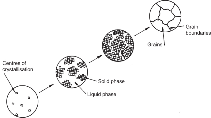
Figure 6.3 Crystal formation and grain growth.
6.2.4 Recrystallisation
This is an important feature in manufacturing with metals. When a metal composed of many crystals, that is, a ‘polycrystalline metal’, is deformed the crystals are twisted and strained. If the metal is now heated to a high enough temperature new equiaxed and unstrained crystals will be formed from the original distorted grains. This process is known as recrystallisation and is illustrated in Figure 6.4. The temperature at which it occurs is different for each metal and varies with the amount of cold deformation that has previously taken place; that is, the more deformation the lower the temperature at which recrystallisation will occur. The recrystallisation process tends to produce uniform grains of comparatively small size. As properties of metal tend to diminish as grain size increases, good control is important to keep the grain size small or at the optimum level for the application. Generally, if metals are allowed to cool slowly after being taken above their recrystallisation temperature, large crystals will form; if they are cooled rapidly, small crystals will result.
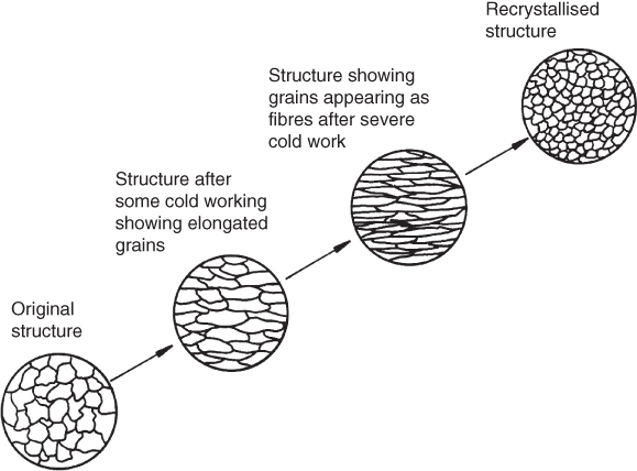
Figure 6.4 Effect on grain structure of cold working and recrystallisation.
When metals are deformed below their recrystallisation temperature, cold working is said to take place. The structure consists of distorted grains and the metal is strain hardened; this can make it difficult to work the metal further. When deformation takes place above the recrystallisation temperature, hot working occurs. A recrystallised structure continually forms and no strain hardening is present. As metals may fracture if deformed too much it is common practice to recrystallise metal at intervals during cold working processes. This restores ductility and prepares the metal for further deformation; this process is known as recrystallisation annealing.
6.2.5 The Importance of Grain Structure
The grain size of a metal depends on the rate at which it was cooled and the extent and nature of the hot or cold working process. A metal with small, fine grains will have better strength and toughness compared to the same metal with large, coarse grains. This is due to the atoms being closer together in the smaller grained metal and causing more interference in the lattice structure when a force is applied. Larger grained metals are characterised by easier machining, more uniform hardenability during heat treatment, but with a greater tendency to crack when cooled by quenching. Additives can be added to a molten metal to promote a specific grain size, for example, aluminium may be added to steel to promote fine grains.
Both hardness and grain size are affected by the temperature history of the metal. Quenching a hot metal quickly from a high temperature will usually harden it, whereas cooling it slowly will give it maximum softness. Annealing is the slow cooling of a metal from high temperature to increase the softness, toughness and ductility while also removing internal stresses.
When a metal is deformed the grains become elongated in the direction of metal flow. This gives the metal the appearance of having a fibre structure, similar to the grain structure in wood. Due to the creation of strain hardening and the fact that the intergranular boundaries will no longer be randomly oriented, the strength and other mechanical properties of the metal will not be the same in all directions, see Figure 6.5. This fact is exploited by engineers, with processes such as rolling and forging being used to impart such properties.

Figure 6.5 The effect of grain direction on component strength.
6.2.6 Alloys
Alloys are formed when metals combine with other metals and, occasionally, with non‐metals. The metals involved usually dissolve in each other in the liquid state to form a completely homogeneous liquid solution. In engineering, metals are normally used in the form of alloys. The most useful alloys contain a large quantity of one metal combined with a much smaller quantity of one or more added elements. These alloys are said to be based upon the metal that predominates in amount, for example, iron or copper based.
Each alloying element has its own unique effect on a metal, the whole effect of two or more elements generally being greater than their individual sum. Carbon is an alloying element with iron that forms steel. The properties of steel are significantly affected by varying the quantity of carbon. Plain carbon steels are therefore referred to as being low (0.05–0.3% C), medium (0.3–0.6% C), or high (0.6–1.4% C) ‘carbon’. Below 0.05% C are the wrought irons and above 1.4% C are the cast irons. In the steels, tensile strength, yield strength and hardness increase with carbon content, whereas impact strength and ductility are decreased.
6.2.7 Some Typical Engineering Metals
- Wrought iron. Though first made as long ago as the late eighteenth century, wrought iron is still a useful material where toughness and resistance to shock is required at relatively low cost. It usually has between 0.02% and 0.03% carbon, and may be used for such things as anchor chains and crane hooks.
- Cast irons. These are relatively cheap materials, made with various alloying elements, to give a range of types with differing properties. The carbon content varies from 2.0 to 3.6%, depending on the particular cast iron being made. Alloying materials, such as silicon to improve fluidity and hence ease of casting, and manganese to increase hardness and strength, are used. In comparison to steel, cast irons are usually of lower strength and more brittle, but easier to cast. They absorb vibrations well and are often found as parts of the structure of machine tools.
- Mild steel. This is the most popular ferrous material and is widely used in the manufacture of motor cars, ships and household goods such as washing machines. It is relatively cheap, is easy to machine, and is available in a wide variety of shapes and sizes. It is normally in the ‘low carbon steel’ category described previously. ‘Medium carbon steel’ provides higher strength and may be used for parts such as gears, axles and other mechanical parts.
- High carbon steels. These steels can be hardened and tempered to give precise hardness, strength and wear resistance characteristics. Cutting tools, screw drivers, press tools, cutlery, chisels, drills and saws are some uses of this material.
- Alloy steels. Although all steels are alloy steels, that is, they all contain carbon and other elements, such as molybdenum that increases strength and hardness, the ‘alloy steels’ have had a number of additional alloying elements added. Control of the manufacturing process is more precise than in the previous types to ensure a high quality metal that closely conforms to specification. Only a few of the possible alloying elements are noted here. The addition of nickel improves toughness and impact resistance. Chromium increases resistance to wear, abrasion and corrosion; it also improves hardenability. Molybdenum increases hardenability and toughness. Vanadium improves impact and fatigue resistance. At high temperatures added tungsten will form hard tungsten carbides. When tungsten and vanadium are combined in steel the resulting material is known as High Speed Steel (HSS), which is used for cutting tool materials.
- Tool steel. This is an alloy steel able to be heat treated to give very good hardness for use in metal forming and cutting dies. Such steel may contain over 18% tungsten and will retain its hardness at high temperatures.
- Stainless steel. This is an alloy steel with more than 12% chromium and usually also containing nickel. It has very good resistance to corrosion and is used for cutlery, food processing equipment, sink units, valve and pump components, dies and so on.
These are only some of the wide range of ferrous materials commonly available. The non‐ferrous materials also provide a wide variety of characteristics. Like the ferrous materials they are most useful in engineering in their alloyed forms.
- Aluminium alloys. These are used where a light weight is required. In its pure form aluminium has good electrical conductivity and corrosion resistance. The alloyed form is much stronger but less corrosion resistant. Alloying elements such as copper, silicon, manganese and zinc are commonly used. For special applications, such as satellite construction where lightness and stiffness are required, lithium has been used. However, lithium reacts explosively with water thus necessitating more expensive manufacturing procedures.
- Copper. Copper has extremely low electrical resistance and is corrosion resistant. However, it is both soft and expensive in its pure form. It is therefore usually alloyed to provide bronze, brass and other materials.
- Bronze. Bronze is an alloy of copper with tin, aluminium, manganese or silicon. It is corrosion resistant and relatively strong.
- Brass. Brass is an alloy of copper with zinc. It has good corrosion resistance, is easily machined and cast, but can be less strong than bronze.
- Titanium. Titanium and its alloys, though expensive to produce, have generally high strengths up to 500°C and are highly resistant to corrosion. This makes them a cost‐effective solution to many problems in the aerospace and chemical industries.
6.2.8 Heat Treatment of Metals
The final mechanical properties exhibited by a metal product are usually the result of three factors, that is, the alloying materials, the way in which the metal was worked and the heat treatment processes used. The first factor has already been explained, the second will become apparent as the various processes are studied later; heat treatment is briefly considered here. Heat treatment is usually employed to relieve internal stresses built up during cold working of the material, or to harden or soften the material to a specific value to suit a particular application.
- Annealing. The main purposes of annealing are to restore ductility and softness to a metal and relieve internal stresses after it has been hardened by cold working or rapid quenching from a high temperature. It is carried out by slowly heating the metal to an appropriate temperature, keeping it at this temperature for a specified time then allowing it to cool slowly. The annealing process follows the stages of stress relief, recrystallisation and grain growth, as was shown previously in Figure 6.4 .
- Hardening. Steels with a carbon content greater than 0.3% can be hardened by raising them to a high temperature, then rapidly cooling them in a liquid such as cold water. The temperature to which the steel needs to be raised depends on its carbon content and ranges between 720 and 1100°C.
If the steel has a carbon content lower than, say, 0.3% then its surface can be hardened using a process known as carburising. Here the steel is heated to above 900°C in contact with a substance rich in carbon. The carbon in the substance will diffuse into the surface of the steel, forming a skin containing around 0.8% carbon. The carburising substance may be gas, liquid or solid. When the steel is quenched it will be said to have been ‘surface hardened’. It should now have a tough core and hard outer shell that will be wear resistant. In this process, surface areas of the steel that do not require hardening can be protected against carbon penetration by a surface coating such as copper plating.
- Tempering. When steel is fully hardened throughout, it is brittle and is likely to contain internal stresses. It is therefore necessary to reduce this hardness to that required for the application; this ‘tempering’ process will also restore toughness to the structure. Steel is tempered after hardening by reheating it to a specific temperature, usually below 550°C and then cooling it. The exact temperature to which it is reheated determines the final hardness of the metal. For example, a fully hardened chisel made entirely from high carbon steel would be too brittle to use, its edge would crack easily if dropped and, when hit by a hammer, the head would be liable to chip and cause an eye injury from flying particles. The chisel is therefore tempered, the edge is raised to a temperature high enough to remove the possibility of cracking yet ensuring that sharpness is maintained in use, and the head is raised to a higher temperature producing a softer but tougher composition that will not fracture.
Heat treatment of non‐ferrous materials is often restricted to annealing to remove the effects of cold working. Some aluminium and copper base alloys can be hardened using a process called ‘precipitation hardening’.
Where high strength is required at reasonable cost, metals are still the most likely engineering choice. Where special properties of light weight, heat resistance and high strength to weight ratios are required materials such as polymers, ceramics and composites are becoming more popular. However, metals continue to be improved and new forms are always emerging from the world's laboratories. High stiffness steels capable of being useful in very thin light‐weight sheets for car bodies and ultra‐high carbon superplastic steels capable of 1000% deformation have been developed.
6.3 Plastics
6.3.1 Plastics and Polymers
A ‘plastic’ is an engineering material that can easily be moulded into a desired shape, usually at an elevated temperature. After cooling the plastic retains its new shape. In the case of thermoplastics, reheating will allow the plastic to be remoulded. Thermosetting plastics retain their moulded shape even when reheated. Plastics can be transparent, translucent or opaque. They can be produced in any colour or finish desired. They can be used for wrapping chocolate bars, housing computers, replacing human organs or armour plating a tank. On average one new plastic is being created almost every day. In fact, plastics are now so widely used and the variety is so great that major producers provide computer programs, free of charge to users, to assist with the appropriate plastic selection.
Plastics are generally synthetic polymers. Natural polymers have been used for many years. Latex is the sap of ‘rubber trees’ that, when mixed with certain chemicals and allowed to coagulate, can be processed with sulfur and placed in a mould. When the mould is heated a chemical reaction takes place called ‘vulcanisation’; the product is a rubber product that has considerable mechanical strength and has the shape of the mould. Horn is another example. Horn when heated becomes soft and can be moulded. It was used for buttons and in thin translucent sheets it was used as we now use glass. In fact the word ‘lantern’ comes from the term ‘lanthorn’, an early application of the natural polymer.
6.3.2 The Chemical Structure of Plastics
Plastics are synthetic polymers made from organic molecules using the process of synthesis. An organic molecule has carbon atoms as its base; an example of this is the ethylene molecule shown in Figure 6.6a. In the production of plastics this ethylene molecule is known as a ‘monomer’, which means ‘one part’. In the process of synthesis used to manufacture the plastic, conditions of high temperature and pressure may be created, causing one of the links in the central double bond to break. This allows the individual monomers to link up and form a chain, or ‘polymer’, as shown in Figures 6.6 b and c. Around 1000–20 000 of these monomers combine to form one polymer of ‘polyethylene’, which is a simple plastic composed only of carbon and hydrogen atoms. By introducing other atoms or groups of atoms plastics with different properties can be created. For example, chlorine is used to produce polyvinylchloride or PVC and fluorine can be used to create polytetrafluoroethylene or PTFE.
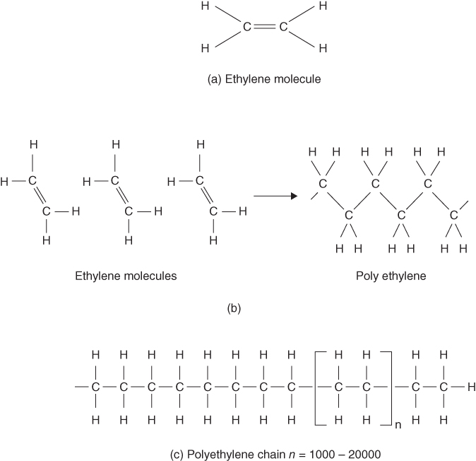
Figure 6.6 Organic molecules.
The manner in which the polymer chains arrange themselves with respect to each other influences the properties of the final plastic. In the thermosetting plastics the molecular chains are designed so that further chemical linking can occur between the chains themselves. This produces a three‐dimensional network structure that forms as the plastic is being moulded under heat, see Figure 6.7a. This produces a very strong plastic with good hardness and stiffness but is usually brittle. Such plastics do not soften on reheating.

Figure 6.7 Polymer chains: network, linear and branched polymers.
In the thermoplastics there is considerable scope for organisation of the chains to provide different properties. Plastics such as PVC, polyethylene and the acrylics and nylons have linear structures, see Figure 6.7 b. Since the chains are linear they can slide over each other, thus providing a certain flexibility to the plastic. Polyethylene is so flexible it can be used as wrapping film, whereas PVC is relatively rigid unless a ‘plasticiser’ is used. Plasticisers are liquid or semi‐liquid additives that tend to separate out the polymer chains, thus allowing them to slide over each other more easily. Thermoplastics can also have branched structures, see Figure 6.7 c, which are less dense and have an apparently higher strength than the linear ones. Both linear and branched structures often exist together in the one plastic. It is also possible to introduce a crystalline structure into plastics during processing. This improves hardness and stiffness, increases density and decreases ductility.
6.3.3 Some Common Plastics and Their Properties
Generally, plastics provide light‐weight, corrosion resistance, low electrical and thermal conductivity and a low cost to weight ratio. It is also possible to produce plastic products directly in any colour or degree of transparency and with any type of surface finish desired, with no need for secondary operations such as machining or painting. As mentioned earlier, new plastics are being introduced at the rate of a few hundred per year; we therefore concern ourselves with only a few basic types that highlight typical properties available.
Thermosetting plastics now include a wide range of materials. For example, there are the epoxies. These have very good mechanical and electrical properties, good elasticity, toughness, resistance to heat and chemicals and strong adhesive qualities. They are often fibre reinforced and used in structural components such as tanks for holding chemicals. Another group are the phenolics. These are relatively strong and hard but brittle. Widely used for products such as telephone cases, handles and electrical insulators, they are available in many forms; for example, sheet, rod or tube. There are many other thermosetting plastics, for example, alkyds, aminos, polyamides and silicones, all exhibiting their own individual combinations of properties.
Thermoplastics are available in an extremely broad range and some of them are considered next.
- Acrylics. These plastics have good strength properties, especially impact strength, and have very good optical transparency. They can be used for vehicle windshields, goggles, lenses, windows and so on.
- Polyamides. These include the nylons and aramids. Nylon is tough, has good abrasion resistance and is self‐lubricating. It is therefore used for gears, bearings, fasteners and so on. In monofilament form it is used for fishing lines and climbing ropes. Aramids have high tensile strength and stiffness and are used in bullet proof vests and pneumatic tyres.
- Polycarbonates. These have high strength and toughness and good impact resistance. Safety helmets, bottles and machinery guards are some applications.
- PVC. A relatively inexpensive plastic, PVC has a wide range of properties and can be made either rigid or flexible. It does not have high strength or heat resistance. Rigid PVC can be used for items such as signs and pipes. Flexible PVC can be used for flexible tubes, cable insulation, floor tiles and so on.
- Polyethylene. This has good electrical and chemical resistance with mechanical properties dependent on the particular type used. Two of the types are low density, LDPE, used for litter bins, toys, bottles and so on, and high density, HDPE, used for products as diverse as canoes and machine components that require good wear resistance.
Just as with the thermosetting plastics, there are many other thermoplastics. Examples of some are polypropylenes, polystyrenes, polysulfones and polyesters. The variety of types and properties of all plastics is now so vast that selection of an appropriate material for a specific application is best done using the material supplier's own updated computer program or product information catalogues.
6.4 Ceramics
Ceramics, first developed over 7000 years ago for making clay pots, are now used today to protect the surface of spacecraft re-entering the atmosphere. With the demand for materials that can function at increasingly high temperatures and speeds and yet retain their properties of strength, hardness and electrical and chemical resistance, there has been a resurgence of interest in ceramics. Even at normal temperatures ceramics can provide a combination of hardness, lightness, stiffness and resistance to corrosion that most other materials could not better. The main disadvantage, however, is that they are brittle.
Ceramics have been widely used for some time now as electrical insulators in electrical power systems and in items such as sparking plugs where high temperature strength is required. Other applications have been in cutting tools using tungsten carbide and grinding wheels using silicon carbide as an abrasive. Now many new applications are seen due to improved understanding of ceramic constituents, and strict quality controls during manufacture produce less brittle ceramics.
The structure of a ceramic material is a compound of metallic and non‐metallic elements. The covalent and ionic bonds that hold the atoms together in a ceramic material are much stronger than metallic bonds, thus giving the ceramic greater hardness and thermal and electrical resistance than, for example, steel. The structure of a ceramic may be single crystal, or polycrystalline where the smaller the grain size the better the strength and toughness.
Examples of more recent ceramic products are ball bearings and turbine blades. Motor car manufacturers are particularly interested in using them. Ceramic exhaust liners, coatings for pistons and catalytic converters are already in wide use, but in the future it is hoped that much more of a car's engine will be made out of ceramics. Conventional piston engines that can run at high temperatures without the need of a radiator or ceramic gas turbine power units are some of the possibilities.
6.5 Composites
The composites are probably the materials with the highest strength to weight ratio of all the types previously considered. They are relatively expensive compared to metals but in many applications the extra cost is acceptable. One of the first and least expensive composites is glass fibre, which is widely used for boat hulls and less frequently now some car components. The simplest form has short fibres of glass randomly oriented in a matrix of plastic. By using longer fibres and arranging them all to run in the same direction within the matrix greater strength is obtained. By using sheets of these, and laminating them so that each layer has fibres running in different directions, structural aircraft components can be made. Further strength and stability can be obtained by using, within the plastic matrix, fibres that have been woven into a three‐dimensional pattern; this is used in products such as skis. The plastic matrix is usually an epoxy or a polyester. This supports the fibres, protects the fibres from damage, acts as a crack arrestor and transfers stresses to the fibres. The fibres themselves are usually high strength stiff materials, but are sometimes brittle. A composite therefore exhibits the best properties of the plastic matrix and the integral fibres to give a tough, strong and light‐weight structure.
Other examples of other typical fibres used are carbon and the organic aramid ‘Kevlar’. Carbon fibre reinforced plastics are widely used due to their high strength to weight ratio. Applications can be found in aircraft, cars, boats, windmills, satellites, golf club shafts, sports racquets and fishing rods. Kevlar, either on its own or combined with other materials, is used to reinforce many products such as bullet proof vests, cut resistant gloves, bicycle and car tyres, walking boots and military helmets.
Some composites use a variety of materials such as metals, polymers and ceramics. They may be used as the fibres or as the matrix. For example, silicon carbide fibres in a matrix of titanium, a metal matrix composite, is suitable for high speed aircraft structures. Advanced ceramic, metal and polymer matrix composites are expensive, but they are attractive materials for high performance machines, motor cars and aircraft.
6.6 Properties and Testing of Materials
Engineers are normally interested in the physical, chemical and mechanical properties of materials. Typical physical properties are (i) density, this is important for weight, for example, a good strength to weight ratio is imperative in aircraft structures; (ii) thermal and electrical conductivity; (iii) melting point, which is important in manufacturing as it determines the ease with which the material can be cast and also the amount of energy required for the process; (iv) magnetic properties; (v) colour and (vi) coefficient of thermal expansion. Chemical properties such as the ability to resist corrosion are also important. However, it is the mechanical properties that often have the greatest influence on the manufacturing methods used to work the materials. Tensile, compressive and shear strength, hardness, ductility and impact and fatigue resistance are all relevant. They are described more fully next.
6.6.1 Stress, Strain and the Strength of Materials
It is essential to understand the meaning of these the terms ‘stress’ and ‘strain’ before proceeding further. When a material is subjected to an axial load, as shown in Figure 6.8, two things happen to it: (i) it becomes deformed; this deformation is termed ‘strain’ and is defined quantitively as the change in length divided by the original length; (ii) internal forces are set up within the material to resist the applied forces; this is called ‘stress’ and it is defined quantitively as the force exerted by the load divided by the cross sectional area of the material.
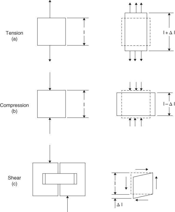
Figure 6.8 Tensile, compressive and shear loading and the resulting strain effects.
A simplified stress strain diagram for a low carbon steel is shown in Figure 6.9. Up to the proportional limit the material obeys Hooke's Law, which states that stress is directly proportional to strain; this ratio is known as Young's Modulus or the modulus of elasticity. Either on or just above the proportional limit, the elastic limit occurs; beyond this point increases in strain do not require proportionate increases in stress. Elongation is now unrecoverable and is known as plastic deformation; usually when this happens the metal is said to have ‘failed’. It is in this plastic region, before rupture occurs, that plastic deformation is used to shape a metal product in many manufacturing processes.
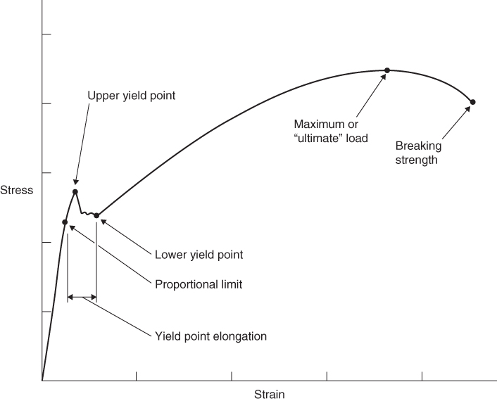
Figure 6.9 Stress/strain diagram for a low carbon steel.
6.6.2 Tensile Strength
This is the strength exhibited by a material when it is being pulled apart from two opposing directions. Tensile strength is determined by pulling on the two ends of a specimen machined, as shown in Figure 6.10. When the specimen is pulled the smaller diameter section necks down from an area A to an area A′, and the gauge length increases from L to L′. For most engineering purposes the area A is used in all calculations since A′ is difficult to measure. From the data collected while pulling the specimen, a curve can be plotted from the two values of stress and strain where:
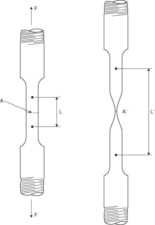
Figure 6.10 A tensile test specimen.
The value of stress where necking begins is called the Ultimate or Tensile Strength of the material.
6.6.3 Compressive and Shear Strengths
Figure 6.8 b,c shows the effects of compressive and shear forces on a material. The compressive strength of a material shows its ability to resist squeezing forces without crumbling or cracking. Shear strength is exhibited by a material when resisting slightly displaced opposing forces, tending to cause adjacent parallel planes of the material to slip over one another; shear strength is often about 50% of the tensile strength. There is also torsional strength; this is exhibited when a material resists a twisting force and is often about 75% of the tensile strength. To ascertain these strengths the material can be subjected to compressive, shear and torsional stresses and strains, and in each case the appropriate load values noted at point of failure.
6.6.4 Hardness
There are several techniques used for determining the hardness of a material, but most industrial methods measure the resistance of the material to penetration of a small sphere, cone or pyramid. Initially, the penetrator and material are forced into contact with a predetermined initial load. An increased load is then applied to the penetrator and the hardness reading is obtained by noting the difference in penetration caused by the final load as compared to the initial load. One of the more common scales used is the ‘Rockwell’ test in which the load applied and shape of the penetrator are specified, see Figure 6.11.
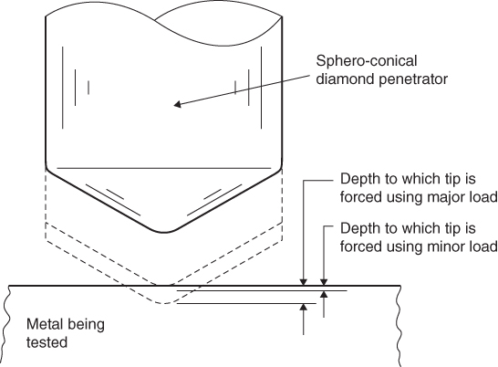
Figure 6.11 Rockwell hardness test.
6.6.5 Ductility
The ductility of a material indicates how much it can be bent, drawn, stretched, formed or permanently distorted, without rupture. Normally a material that has high ductility will not be brittle or very hard. Conversely, hard materials are often brittle and lack ductility. The tensile test can be used as a measure of ductility by calculating the percentage elongation of the specimen upon fracture.
6.6.6 Impact Resistance
A material may be hard and have a high tensile strength, but it may still be unsuitable for an application that requires it to withstand impact or sudden load. A number of tests are used to determine this impact resistance. Two common tests are the Izod test and the Charpy test, in which a notched specimen is struck by an anvil mounted on a pendulum. The energy required to break the specimen is an indication of the impact resistance of the material. For some common engineering materials this energy can vary quite dramatically with temperature, even at temperatures close to ambient. The Izod test is illustrated in Figure 6.12.
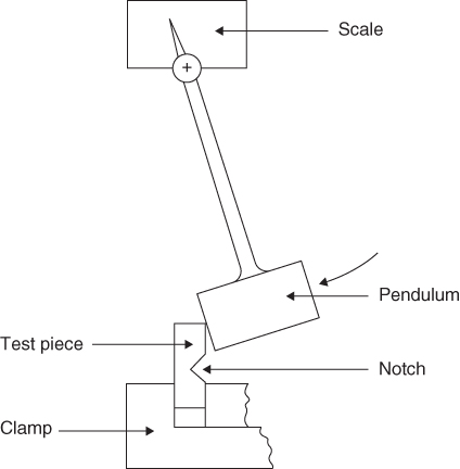
Figure 6.12 Izod impact test.
6.6.7 Fatigue Resistance
The yield strength is useful for designing components that are subjected to a static load, but for cyclic or repetitive loading the endurance or fatigue strength has to be known. This is found by loading the part and subjecting it to repetitive stress. Usually, a number of specimens of a material are tested at various loadings and the number of cycles to failure are noted.
6.7 Conclusion
The variety of materials available to the engineer is vast. He or she must make optimum use of them if his product is to be competitive in the market place. A knowledge of materials is therefore essential not only for product design but also for consideration of how the product will be manufactured. The next chapter now describes how some of these materials are produced from natural resources.
Review Questions
- 1 Give an example of each of the following types of material together with a typical use: (a) ferrous, (b) non‐ferrous, (c) organic, (d) inorganic.
- 2 What type of atomic bonding is exhibited by metals and what implication has this with respect to their properties?
- 3 What is meant by ‘grain formation’ in metals?
- 4 Discuss the significance of grain structure and the importance of recrystallisation.
- 5 What is an alloy?
- 6 In steels, how are properties generally affected by carbon content?
- 7 Describe two ferrous alloys and their uses.
- 8 Why are ferrous metals hardened and tempered?
- 9 What are polymers and why are they useful?
- 10 What is the main difference between a thermoplastic and a thermosetting plastic?
- 11 Describe two polymers and their uses.
- 12 What combination of properties makes ceramics attractive for today's product designers?
- 13 Why have ‘composites’ become desirable for products such as the structural elements of aircraft?
- 14 What do the terms ‘stress’ and ‘strain’ imply when materials are subjected to an axial load?
- 15 Briefly review the types of material properties of interest to product designers and manufacturers.