
8
Casting
8.1 Introduction
Casting is the process of pouring or injecting molten metal into a mould and then allowing it to solidify. Products weighing many tonnes or just a few grams can be produced in a variety of surface finishes and accuracies; internal cavities are also possible. It may be that casting is only the first process in a series of operations that will lead to the finished product, or the desired item may be cast with such precision that it can be fully utilised immediately in the ‘as cast’ condition.
The process is probably one of the earliest, dating from about 4000 BC. However, in recent years much refinement has taken place and a variety of techniques have been devised to satisfy different needs. There are still some problems experienced generally with castings due to their metallurgical structure, as relative to other processes they tend to have lower toughness and ductility and porosity can occur.
As the metal cools in the mould from the molten state and solidifies, it also begins to contract. This means that, if parts of the casting cool before others, depressions can appear on the surface and cavities can occur internally. The problem can be decreased by ensuring that there is always molten metal available to fill the spaces as they begin to grow. This is achieved by providing a ‘head’ of metal in reservoirs in the case of gravity fed moulds and injecting the metal under pressure in the die casting processes.
8.2 Ingot Casting
This is a preliminary process in which the metal is cast in the form of ingots. These are usually further worked by rolling, forging or extrusion to produce sheet, strip, rod, tube or other forms such as ‘T’ beams for the construction industry. Any type of metal may be cast into ingots but steel is primarily considered here.
Steel ingots are often cast into large iron moulds. These hold several tonnes of metal and are tapered slightly so that the mould can be lifted clear of the cooled ingot. A phenomenon that appears here is ‘piping’. This happens because of the relatively rapid cooling of the metal in contact with the mould surface; as the metal cools from the outside in so the shape shown in Figure 8.1a is formed. These ‘pipes’ are undesirable as impurities tend to gather in the vicinity of the pipe surface; this surface also tends to oxidise. When the ingot is further worked, say by rolling, then this surface may become an internal feature of the rolled component and thus be a source of weakness in the finished product. Slow pouring of the metal can lessen the problem, or for smaller ingots reversing the mould and mounting it on trunnions to allow it to be rotated for ingot removal and using a ‘hot top’ as shown in Figure 8.1 b also provides good results. In both methods the top region must be cut off and rejected due to the high impurity content.

Figure 8.1 Ingot casting and effect of mould orientation on piping.
8.3 Continuous Casting
Continuous lengths of slabs, bar and other sections are produced in ferrous and non‐ferrous alloys using this process. The product may be used as cast or further worked to give stronger directional properties. Continuous casting is a process that is popular for producing steel slabs for rolling work. It is more efficient for this than casting ingots, transporting them to energy hungry ‘soaking pits’ that reheat them to hot working temperature before being rolled by a massive rolling mill into slabs. It also removes the problem of rejecting the top part of the casting because of impurities, the problems of piping and mould spatter and the cost of the ingot mould.
Continuous casting installations often comprise part of an integrated steel plant as described in Chapter 7. The molten metal is poured into a water cooled mould open at the top and bottom, as shown in Figure 8.2. There are a number of variations in the process but the two methods shown illustrate the basic principle. The retractable base is drawn downwards at a rate that allows the metal to solidify and yet keeps pace with the metal being poured. As the metal passes through the water cooled moulds it is transported along a path using rollers. Careful control must be maintained over the cooling rate and speed of casting as the material uses its solidified skin to support itself. The mould is often made of copper and to ease the movement of the casting it is usually vibrated and lubricated with a graphite type material.

Figure 8.2 Two methods of continuous casting.
8.4 Sand Casting
There are essentially two types of sand casting; these are ‘green sand’ and ‘dry sand’. In the former the moist sand contains between 2 and 8% water. This is the most common method used to produce castings weighing from under half a kilogram to around 4 tonnes, and where high precision and surface finish are unimportant. It can be used for ferrous and non‐ferrous metals and the easy collapsibility of the mould reduces the stress and strain induced in the casting, so making it suitable for intricate work. The dry sand technique is used for large and very heavy castings. The sand is strengthened by giving the mould surfaces a refractory coating, which is dried before pouring the molten metal. This section is primarily concerned with green sand casting.
Figure 8.3 illustrates the principal elements necessary for the green sand casting of the pipe shown in Figure 8.3 a. First a wooden pattern is made by a patternmaker. This pattern, shown in Figure 8.3 b, includes an allowance for contraction of the metal in the mould and if necessary a slight taper or ‘draft’ on the surface to allow easy removal of the pattern from the sand. As a hollow section is required a ‘core’ must be made. This necessitates the construction of the core box shown in Figure 8.3 c.

Figure 8.3 Sand casting elements. (a) Required component, (b) upper and lower patterns, (c) core box, (d) an assembled mould and (e) view of mould section A – A.
The sand for the main mould must have the following properties. It must be able to withstand high temperature, that is be refractory. It must be able to retain its given shape, that is, be cohesive. And it must be able to permit gases to escape, that is, be permeable. Most of the sand, up to 90%, is composed of silica that provides the refractoriness, between 4 and 8% is clay to provide cohesiveness and the remainder may be composed of iron oxide, coal dust and water, which contribute to the permeability once subjected to the heat of the molten metal. The core produced in the core box is composed of similar sand to the main mould, but it is further strengthened by additional bonding agents.
Figure 8.3 d and e shows an assembled mould. The moulding box containing the green sand mould has an upper portion, the ‘cope’, and a lower, the ‘drag’. The two parts are held in precise relation to each other by means of the locating dowels.
As well as the mould cavity it can be seen that there is also a pouring basin, a sprue, runner and gate system and a riser. The pouring basin provides a facility for efficient entry of the molten metal, the sprue provides a reservoir and ‘head’ of metal, the runner is designed to carry ample supplies of molten metal rapidly to all areas of the mould cavity, and the gate is designed to provide a controlled flow of molten metal into the cavity and a point at which the casting can easily be broken off from the rest of the sprue and runner material. The riser accepts the overflow of metal from the cavity and again acts as a reservoir and ‘head’ of metal.
To produce the mould as shown, the cope and drag halves are initially made separately. The bottom pattern half is laid flat side down on a moulding board with the drag half of the moulding box around it. Moulding sand is then riddled over the pattern and rammed down sufficiently for the particles to adhere together; the sand is then cut level with the edge of the box. The box is turned over and the pattern removed. This process is repeated with the top half of the pattern and wood forms to make the runners, risers and so on. After making the sand core in the core box the core is laid in the impressions formed by the core prints in the drag section. A fine layer of dry, clay free, parting sand is sifted onto the sand surface; this prevents the cope from adhering to the drag. The upper half is then placed on the lower and the pouring of the molten metal can begin. When the casting has cooled and has been removed the sand core is broken up and shaken out, thus leaving the completed hollow pipe. Although a simple product has been shown here the same technique is followed for most products made by this casting process.
The advantages of sand casting are that almost any metal can be used, there is virtually no limit on the size and weight of product, high complexity is possible, tooling costs are low and the route is direct from pattern to mould. The disadvantages are that some machining is usually necessary, surface finish is poor, it is difficult to achieve close tolerances and it is not practical to cast long thin sections.
8.5 Centrifugal Casting
Long, hollow, cylindrical castings are commonly produced without the use of a central core using this process. The permanent cylindrical metal mould is rotated at a high speed, usually between 300 and 3000 rpm, while molten metal is poured into it. The centrifugal force created by the spinning, which pushes the molten metal against the cylindrical surface of the mould; this produces a hollow cylinder of uniform wall thickness. A good dense structure is obtained with all of the lighter impurities concentrated on the inner face, thus allowing them to be easily removed by machining the bore.
The advantages of the process are that the centrifugal force facilitates complete filling of the mould, the gases and impurities concentrate on the inner surface for easy removal, a good solid outer surface is obtained and the mould is relatively simple. The main disadvantages are that the process is limited to symmetrical products and that if alloys of separable compounds are being cast these compounds may not be evenly distributed.
8.6 Shell Moulding
This is essentially a sand casting process in which the clay used for bonding in the green sand process is replaced by a synthetic material of the phenol‐ or urea‐formaldehyde type. Figure 8.4 shows the five stages of the process. The patterns must be made of metal due to the relatively high temperature required for the setting of the bonding material. The process is carried out as follows. (1) The pattern and plate are heated to around 250°C and coated in silicone oil to aid stripping. The dump box containing the sand and the thermosetting resin mixture is attached. (2) The box, which is mounted on trunnions, is rotated and the sand mixture falls over the pattern. The resin melts and hardens, the resulting thickness of the shell depending on the pattern temperature and the length of time the sand is allowed to remain in contact with the pattern. (3) The box is again inverted and the uncured sand falls back into the box; the partially cured material is left adhering to the pattern. The shell thickness is usually about 3 mm. The shell and pattern are then removed from the box and placed in an oven for about two minutes at 315°C; this finally cures the shell. (4) The hard shell is stripped from the pattern. (5) Two shells are fixed together to form the completed mould. They are usually placed in a pouring jacket and supported by sand or shot. The molten metal is then poured in. This process provides a rapid production rate, a good grain structure and a good surface finish and accuracy, thus minimising finishing operations. However, it does require expensive patterns, equipment and resin binder, and there is a limit to the size of part that can be made.
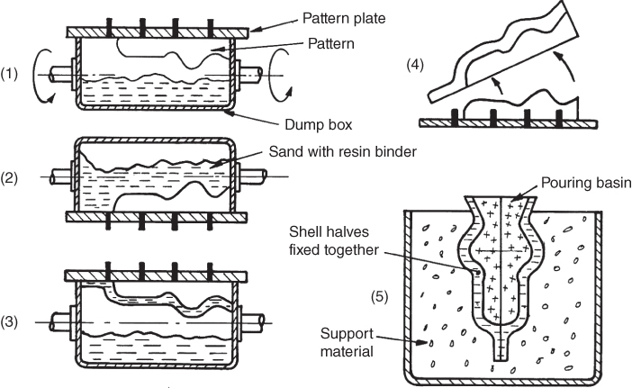
Figure 8.4 Stages in shell moulding.
8.7 Full Mould Process
A consumable polystyrene pattern is used in this process. Complex product shapes, together with the pouring basin, sprite and runner systems are formed in foamed polystyrene. The patterns are packed in sand and when the molten metal is poured they instantaneously vaporise. Though originally a one off type process suitable for prototype production, the process has been applied for large volume production using metal dies for mass producing the polystyrene patterns.
The process has the advantages that expensive wooden patterns do not have to be made and that as the pattern does not have to be withdrawn, the need for taper or draft on the pattern is eliminated. Some machining is usually required to achieve the desired precision and surface finish, though this has been reduced due to improvements in the process.
8.8 Investment Casting
Expendable patterns are again used here. However, in contrast to the full mould process high precision products with good surface finishes are obtained in large volume production. The ‘lost wax’ investment casting process is described visually in Figure 8.5.
- A metal die is made with a cavity conforming to the desired shape of the component. Wax is injected or poured into the die cavity. When the wax has cooled the die is opened and the wax pattern is removed. A large number of patterns are usually made.
- The wax patterns are welded onto a wax sprue and runner system to form a ‘tree’.
- The wax tree is dipped into a fine slurry of refractory material and plaster. This will provide the smooth interior surface of the finished mould, which is capable of replicating intricate detail.
- The tree is now further coated by dipping or spraying with a coarser refractory material to give the mould additional strength. This step is repeated a number of times to increase the wall thickness.
- The tree is placed upside down in an oven at a temperature of approximately 95°C. This melts out the wax and dries out the investment or coating.
- The mould is now preheated in a furnace to a temperature of between 650 and 1050°C. This allows the poured molten metal to flow freely into all corners of the mould. It also promotes sympathetic contraction of the mould and casting thus providing better dimensional control. When the casting has cooled the mould is broken away leaving the finished components attached to the sprue and runner system.

Figure 8.5 Investment or ‘lost wax’ casting process.
The process provides high dimensional accuracy and an excellent surface finish, components of extreme intricacy can be produced in almost any metal, a good size range is available from a few grams to around 40 kg. The main disadvantages of the process are the high cost of the metal dies and the time consuming manufacture of the moulds.
8.9 Die Casting
For high volume production of non‐ferrous and some ferrous items, die casting is the most likely casting process to be used. In this process molten metal is injected under high pressure into precision made metal dies. These dies have sprue, runner and gate systems just as in the other casting processes. The metal is held in the die under pressure until solidification takes place; the finished item is then automatically ejected. The machines and dies are expensive and are therefore financially viable only where large numbers of castings are required. The machines come in two forms, that is, ‘hot chamber’ and ‘cold chamber’; these are shown schematically in Figures 8.6 and 8.7. In both sketches the hydraulic rams and toggle arrangement for clamping the moving portion of the die to the fixed die during metal injection would be located to the right of the chamber.
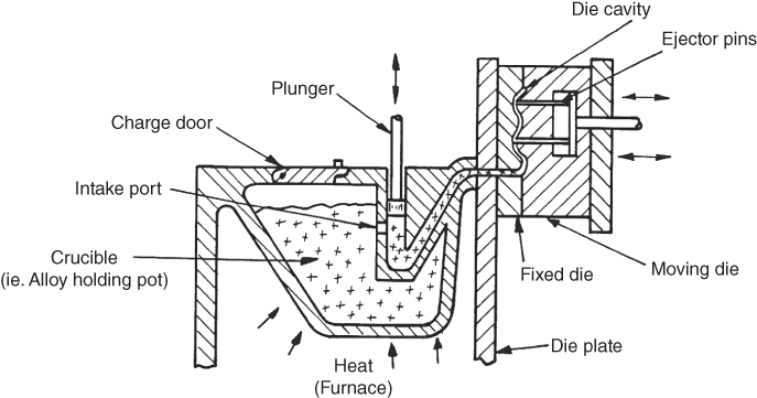
Figure 8.6 The hot chamber die casting process.

Figure 8.7 The cold chamber die casting process
In the hot chamber process a ‘gooseneck’ duct is partially submerged in the molten metal held within the crucible. There is an intake port opening from the crucible into the duct. A plunger is shown operating vertically. On the downward stroke of the plunger the molten metal is forced into the die. When the plunger returns to its original position the chamber is refilled with the molten metal flowing through the intake port. This produces a fast operation and short cycle times are obtained. The direct injection of the molten metal from the melting pot into the die chamber makes this a relatively efficient process. It is not used with the higher melting point metals but is commonly used for the zinc and tin based alloys. It is also suited to automated operation.
For the higher melting point alloys, such as those of aluminium, magnesium and copper, the cold chamber process is used. In this process the molten metal is ladled into the ‘shot’ chamber; it is then pushed forward by the plunger and injected into the die cavity.
Due to the high pressures involved, for example, in the hot chamber process, the metal is injected at about 15 MPa and in the cold chamber between 20 and 70 MPa; large forces must be applied by the machines to keep the dies closed during operation. Thus, die casting machines are rated according to the force they can apply, typically they range from about 25–3000 tonnes or approximately 200–27 000 kN.
The advantages of die casting are: high production rates, high precision, high quality surface finishes, high integrity castings with low porosity and good grain structure, and complex castings with thin walls can be made. These advantages have to be paid for in the expensive machines and tooling that are required. It is therefore not a viable process to select if quantities and production rates are not high enough to produce an adequate return on investment.
8.10 Defects in Castings
A number of defects can occur in casting; the more common are listed next with a comment on their likely causes.
- Shrinkage. This is evidenced as internal porosity or cavities, or as depressions on the surface of the casting. Improvements and additions to the risers in the mould design should remove the problem.
- Scabs. These are rough lumps of excess metal on the surface of sand castings. Probably caused by poorly rammed sand or sand with insufficient binding material.
- Fins. This is the term given to the excess metal occurring along mould parting lines. It is caused by poor fitting of the mould halves and possibly other mould components such as cores and inserts.
- Blow holes. Internal cavities in the casting caused by gas. The gas is originally present in the molten metal and as the metal solidifies it is rejected from solution so producing the cavities. Commercial degassing agents should be added to the melt.
- Blows. Cavities on or near the casting surface. They are caused by poor mould venting and, in the case of sand casting, caused by gases emanating from the mould due to excess moisture and poor permeability.
- Inclusions. These are slag, oxide or sand particles evident in a finished sand casting. They are caused by poor skimming or fluxing of the melt prior to pouring, and poorly made sand moulds lacking cohesiveness.
- Cold shuts. ‘Seam’ like discontinuities in the casting. They are formed when two metal streams meet inside the mould but have insufficient fluidity to allow them to break the oxide films that separate them. Improved mould design is necessary to ensure that the runner and gating system carries the molten metal rapidly enough to all areas of the mould cavity.
- Misruns. Incomplete castings caused by the molten metal not penetrating throughout the mould. Usually caused by the metal being poured or injected at too low a temperature or pressure.
- Hot tears. Cracks in the casting. Caused by stresses set up during contraction of the casting through poor mould design and in the case of sand casting through the use of cores lacking in collapsibility.
- Porosity. This is said to exist if fluids can be transferred through the metal even though the pores are invisible. May be caused by contamination of the metal.
- Warping. This is distortion of the finished casting due to poor mould design.
8.11 Cleaning of Castings
When the casting is removed from the mould it is attached to the sprue, runner and riser system. It must be separated from these and in addition any ‘fins’ or other surface protrusions must be removed. The sprue and runner system is removed at the gating points by hammering, flame cutting, grinding or sawing. Pneumatic chisels may be used on larger castings. This initial process is termed ‘fettling’. The sand left adhering to sand castings can be removed by vibration or shot/sand blasting. For polishing and cleaning the casting surface and removing fins and rough edges, tumbling the castings in a cylindrical steel drum is sometimes used.
8.12 When to Use Casting
There are a number of indicators that would suggest when it would be advantageous to select a casting process in preference to another manufacturing technique. These are outlined next.
- When the product required has large heavy sections of complex shapes, a process such as sand casting may be more efficient than fabrication and machining.
- When using materials that are difficult to machine, for example refractory materials, casting to fine tolerances using investment casting may be an attractive solution.
- When large production volumes of small to medium sized complex components are required in zinc or aluminium alloys, then pressure die casting is often appropriate.
- When the desired component has a complex structure, possibly with re‐entrant angles and internal cavities, then casting could be the only technique possible.
- When vibration effects have to be absorbed, for example, the damping of machine tools to decrease the effects of mechanical vibration and noise, then sand casting of components in grey cast iron is often carried out.
- When it is necessary to produce items, such as machine pedestals and base plates, in which masses of metal have to be strategically placed, casting is usually preferable to fabrication.
- When single items are required quickly, as in the case of prototypes, then the ability to produce a pattern rapidly, as in the full mould process, makes casting attractive.
- When directional strength properties are not desired in the finished component.
- When valuable or precious metals are to be used, casting provides a technique that minimises wastage.
- When it is possible to design or redesign the product in such a manner that components that were originally separate can be integrated into one unit.
Review Questions
- 1 What is the phenomenon called ‘piping’ in ingot casting and why is it undesirable?
- 2 Continuous casting is now more popular for making steel slabs than the rolling process. Discuss why this is so.
- 3 What is the difference between ‘green sand’ and ‘dry sand’ casting?
- 4 Describe three requirements for a good moulding sand.
- 5 State one further requirement of the moulding sand necessary during and after the casting has cooled.
- 6 What is the function of a ‘core’ in sand casting and how is it made?
- 7 Explain the function of the following casting elements: sprue, runner, gate and riser.
- 8 State why the structural integrity of products made by centrifugal casting is generally good.
- 9 Describe, with the aid of sketches where necessary, the stages of the shell moulding process.
- 10 Give two reasons why the full mould process is particularly suited to prototype manufacture.
- 11 Describe, without the aid of sketches, the lost wax process.
- 12 Discuss the differences between the hot and cold chamber die casting process, and state under what conditions each may be used.
- 13 List six defects commonly found in castings and discuss how they could be avoided.
- 14 What is meant by the term ‘fettling’ and how is it carried out?
- 15 State the casting processes you would select to produce the following items and give reasons for your answer in each case:
- 1. Small complex steel components, 50 mm × 40 mm × 10 mm; a tolerance of ±0.05 mm and a good surface finish is required; quantities will be 2000 per week.
- 2. Motor car wing mirror mountings. A tolerance of ±0.1 mm and a special textured surface finish is required; the material will be a zinc alloy and 2000 per week are required.
- 3. Bowl shaped stainless steel pump casings for nuclear reactors. The outside diameter is 1 m and the wall thickness is 150 mm. The tolerance is ±2.5 mm as the component will be finished by machining; 4 per month are required.
- 4. A seamless, steel, pressure vessel 2.5 mm long, 0.5 m diameter, with a wall thickness of 10 mm; the tolerance required is ±1 mm; 500 are required and a good sound casting with no internal flaws is necessary.
- 5. A pedestal to hold a prototype cutting machine; accuracy and surface finish is unimportant, the material will be grey cast iron.