
11
Pressworking
Presswork involves carrying out the processes of shearing, bending and drawing in a press that usually holds a press tool. Presswork is the most economic method of mass producing components from sheet metal. Historically, the use of presses allowed the economic production of products so that they could be sold at affordable prices. Products such as clocks, cash registers and adding machines were totally dependent on their components being produced in press tools. However, although products utilising electronics have largely replaced the old mechanical and electromechanical designs, there is still a demand for components made from pressed steel, aluminium and brass. The ubiquitous motor car would be far too expensive for wide ownership if it was not for the pressed steel panels from which its body is constructed. Frames and panels used for ‘white goods’ such as domestic washing machines, fridges and cookers are made in by presswork. The chassis, electrical tags and connectors, and other sundry components found within televisions, phones, computers and other electronic goods are made in presses. Also kitchen utensils, hinges, radiator panels and many other products are all made from pressworked components.
Presses are capable of very high production rates since the time to produce one component is simply the time for one up and down cycle of the ram carrying the press tool, and the time it takes to feed into the press a new portion of material. In fact, using tools with multiple dies can allow many smaller components to be produced every second. Most press operations are carried out with the material in its cold state. The press itself consists of a machine frame (see Figure 11.1), supporting a bed and a ram, a mechanism to make the ram move at right angles to the bed and a means of powering the mechanism. The power may come from electric motors or hydraulic rams. For fast operations such as punching, blanking and trimming, a press that uses an electric motor to drive a large flywheel is ideal. The energy from this flywheel is transferred to the ram through mechanisms such as cranks, eccentrics or gears. For slower operations such as those involved in squeezing or drawing hydraulic power is better.

Figure 11.1 The basic configuration of a gap press
Some of the operations carried out by presswork are shown in Figure 11.2. In cropping, the material is sheared across its whole width. It is important to remember that when designing and manufacturing the tool that in blanking, an aperture is created by shearing, the material that is removed is the required part and it takes the dimensions of the die (there always needs to be clearance between the punch and the die). Holes in components are created by piercing the dimension of the hole taking the dimensions of the punch. In bending, two‐dimensional deformation takes place, care being required in the tool design to prevent cracking and maintain dimensional accuracy. In drawing, the material is stretched in three dimensions to typically produce a cup shape and careful design of the tooling is again required to prevent wrinkling or rupturing of the metal.

Figure 11.2 Some pressworking operations: (a) cropping, (b), piercing and blanking, (c) bending and (d) drawing.
For most products the press is fitted with a ‘press tool’ that is in two parts, see Figure 11.3 in which a very simple piercing and blanking tool is shown. The top part is fitted to the ram of the press and is therefore free to reciprocate vertically, it is often fitted with the ‘punch’. The bottom part is fixed to the bed of the press and usually contains the ‘die’ it may have a through hole to allow punched blanks or components to fall through the bed of the machine into a bin or conveyor belt. Assuming the press has adequate capacity it is easy to change from one product to another by simply changing the press tool. The tools themselves can be very expensive depending on their complexity. The top and bottom ‘sets’ may be made from cast iron and the punch plate from steel. The punches and bottom die will be made from hardened steel as would be the pressure plate which prevents the hardened punches being pushed into the top set. The alignment between top and bottom parts is maintained by pillars set into the bottom die and bushes in the top die.
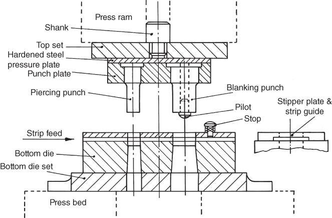
Figure 11.3 A simple piercing and blanking tool.
A strip of cold rolled material is fed through the stripper plate in the direction shown until it is midway between the piercing punch and the blanking punch. In this case the stripper plate, which pulls the material off the punches, is fixed and integral with the strip guides. The material may be fed by hand while the system is immobilised, but usually an automatic feed is used. On the first downward movement of the top tool the piercing punch creates the central hole of the washer. When ram with the top section of the tool has risen the material strip is then fed forward until it reaches the spring loaded stop. In the simple configuration shown this stop may be temporarily pushed down by hand while the press will be immobilised. In the case of hand‐fed material the press is immobilised by a failsafe method such as a light guard (see Chapter 28). On the next downward movement of the tool the pilot on the blanking punch locates on the previously pierced hole before the punch comes down and punches out the finished washer. The purpose of the pilot is to ensure concentricity of the inner hole with the outer circumference of the washer. The strip is then fed the pitch length shown between each stroke of the press.
The press tool described here is a two stage tool but far more complex multi‐stage or ‘progression’ tools are commonly used. These have multiple punches and a large number of stages through which the material is fed before the first component is produced. It is apparent that after the material has passed through the final stage each press stroke produces a component and this is why presswork can produce such high volumes of components at such rapid rates and why it remains such a useful process. Other tools, called ‘combination’ tools, combine a number of operations in the one stage, for example, blanking and drawing. These can be used for producing components that are dish, cup or tube shaped.
The component shown in Figure 11.4 will have been produced in a progression tool where initial operations will have involved the piercing of the holes, the strip will then have been progressed through the press tool for subsequent operations such as drawing and blanking and creating the 90° bend.
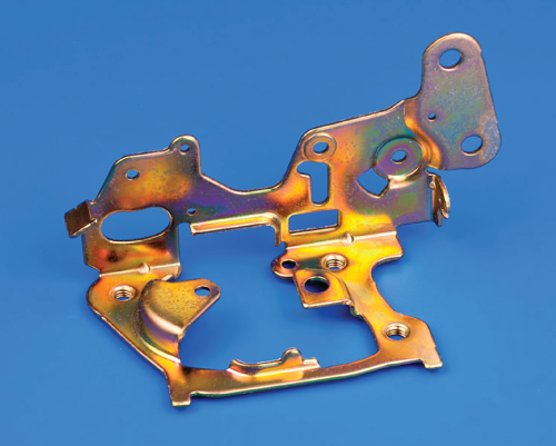
Figure 11.4 A typical small component produced by presswork.
In the car industry body panels such as those shown in Figure 11.5 are produced in large transfer presses. In these operations the body panels are blanked from sheet steel or aluminium, they are then lifted and transferred mechanically to the next pressing operation and so on until the panels are completely formed.

Figure 11.5 A car body panel produced by presswork.
Source: Image Courtesy of Audi.
The selection of the specific pressing process and the design of the press tools require much skill and experience. Knowledge of the properties of the material that is being worked regarding shear strength and ductility is essential. The actual clearance between the punch and the die is important. It is clear that the punch has to be smaller than the die and the amount by which this is necessary is generally dependant on the shear strength and the thickness of the material being worked. Typically, this will be between 10 and 35% of the material thickness. As the punch first enters the material it produces a slight curvature on the surface of the surrounding material and smooth sides on both the pierced and blanked surfaces. As it passes further downward the material fractures and a slightly wider and rougher surface on the sides is apparent. The width of the part pushed out by the punch will be that of the die and the width of the hole left by the punch will be that of the punch. If the part has not been put through another process, such as tumbling to remove burrs and sharp edges, or a shaving operation where a small amount of material is additionally removed from the sides to improve accuracy, then it is possible to see the smooth and rough witness marks and so understand the direction in which the part was formed.
This chapter is intended to illustrate the principles of presswork and introduce some types and operations. However, just as parts produced by pressworking are ubiquitous and numerous so also are the varieties of presswork available – many more than are mentioned here. They are likely to be the major source of low cost, mass produced, sheet metal part for many decades to come.
Review Questions
- 1 State reasons for the continuing popularity of presswork as a means of producing components.
- 2 Name four types of operation that are commonly carried out by presswork.
- 3 Briefly hand sketch a simple piercing and blanking tool.