
12
Plastics Processing
12.1 Introduction
This chapter is concerned with the manufacturing processes used for making plastic components. Plastic materials were discussed in section Chapter 6, where their importance to modern technology was also noted, and the production of plastic was described in Chapter 7.
One of the major advantages of plastics is that, by choosing a suitable moulding or forming process, a complete component can be produced that requires little or no finishing operations. As the number of options available to the engineer when selecting the process is large, the optimum will be found only by considering the advantages and limitations of each process, the design of the component to be made, the tool or mould design and the processing characteristics of the plastic being used. A few of the main thermoplastic moulding and forming processes are now explained.
12.2 Extrusion
This is a continuous process in which one or more Archimedean feeder screws are mounted within a cylinder as shown in Figure 12.1. This cylinder is heated and as the screws rotate they plasticise and convey the plastic along their threads from the feeder hopper to a die. The section of this die determines the cross sectional shape of the extrusion. Extrusion machines come in a range of sizes with screws ranging in diameter from 25 to 200 mm.

Figure 12.1 The polymer extrusion process and typical polymer sections.
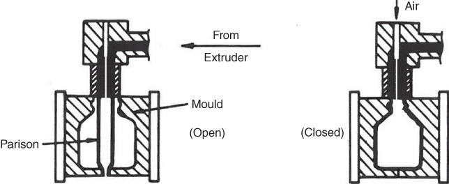
Figure 12.2 The blow moulding process.
Typical products are tubes, rods, sheets and continuous lengths of almost any profile. By modifying the process it is possible to produce products with a combination of materials, for example, by incorporating pressure rolls just after the die the extruded plastic can be bonded to a substrate of another material such as a fabric, paper or metal. By modifications to the die it is possible to include metal sections or wire within the extrusion. In the dual extrusion process plastics of different properties can be combined so that, for example, an extruded strip may be produced, one side of which is rigid and suitable for attachment to (say) a refrigerator door and the other side flexible, thus suitable for forming a seal. Extruded sections are important in providing the plastic in a suitable form for processes such as blow moulding and blown film production. Since extrusion is a relatively fast process, it is suitable for high volume production. To cut the material to length as it emerges from the extruder a flying saw is often used that travels with the material as it cuts. The range of size and sections able to be produced is wide and component surface finish and precision is very good. The machines themselves are expensive, but once the initial investment is made a wide variety of sections can be produced by simply changing the die.
12.3 Blow Moulding
This is used to produce hollow products such as plastic bottles this process utilises short lengths of extruded tube called parisons as shown in Figure 12.2. After extrusion, while the plastic is still hot, an appropriate length of the parison is located in the mould. When the mould closes the bottom end of the parison is closed and compressed air is passed in through the open top. The parison inflates and adopts the shape of the mould cavity. By maintaining the air pressure the plastic is held in contact with the water cooled cavity surface until its shape is stable.

Figure 12.3 Calendering.
Bottles of a multitude of shapes, sizes and transparent, translucent or opaque colours are produced by this method. Soft drinks, detergents, cosmetics, shampoos and so on are all contained in blow‐moulded bottles. Many other lightweight hollow components are produced by this method, although the surface finish is not usually as good as that produced by injection moulding. However, relatively good quality products can be produced at high production rates.
12.4 Calendering
Continuous production of sheet and film plastic is obtained by this process. Beginning as a thick melted paste, the plastic is formed into sheet by passing it between and around a series of nip rollers as shown in Figure 12.3. A calender usually comprises four temperature controlled rolls. A polymer, which may be plastic or synthetic rubber, is fed to the first pair of rolls where the roll separation controls the feed rate. The separation of the following rolls determine the final sheet thickness. Plastic film and plastic and rubber sheets are produced by this process, and a particular advantage is that plastic or rubber can be laminated to other plastic films, sheets of paper, fabrics or metal foil.
12.5 Vacuum Forming
Products of relatively simple form are produced by this process from thin thermoplastic sheets as shown in Figure 12.4. The plastic is clamped in a support frame and exposed to radiant heat until it reaches a pliable state. The frame is then drawn down over a pattern and hermetically sealed to the chamber walls, as shown in Figure 12.4 . A vacuum pump now withdraws air from between the pattern and the plastic, thus causing atmospheric pressure to force the plastic against the surface of the pattern. The combination of the vacuum and the mechanical action on the plastic as it is pulled over the pattern causes the plastic to adopt the shape of the pattern. The plastic, cooled rapidly by air, becomes rigid again and the pattern is withdrawn.

Figure 12.4 Vacuum forming.
Products such as margarine tubs, egg containers, disposable drinking cups and larger items are produced by this method. Care has to be taken with pattern design as the stretching of the plastic tends to create thin walls at component corners.
12.6 The Blown Film Process
In this process, a tube is extruded vertically while at the same time it is inflated by the introduction of compressed air (see Figure 12.5). The extrusion is drawn upwards and through nip rolls as shown, these rolls prevent the air escaping immediately. The air flow is controlled to produce a constant bubble size and wall thickness. The film is flattened by the rolls as it is drawn onto a wind up unit. Between the rolls and wind up unit there may be perforating blades, heat welding clamps and handle cutting punches, these being used to produce the rolls of disposable ‘plastic bags’ widely found in supermarkets. Larger bags and sacks for refuse disposal and holding agricultural products are also produced by the process.
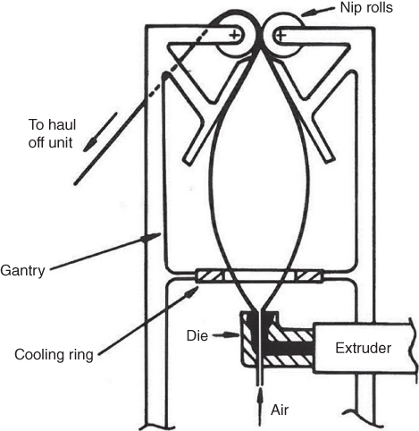
Figure 12.5 The blown film process.
12.7 Injection Moulding
For high volume production, injection moulding is the most widely used and economic of all the thermoplastic processes. Figure 12.6 shows the basic elements of an injection moulding machine, and Figure 12.7 shows the process schematically. The plastic, which is in powder or granular form, is loaded into the feed hopper. This may be done manually, or automatically via tube conveyors from bulk storage bins. The plastic falls from the hopper into the heated machine barrel; this barrel contains a rotating and reciprocating screw, which acts as both a plasticiser and an injection unit. As the plastic passes along the screw flight the root diameter of the screw increases, this compresses the plastic. The shearing action between the particles of plastic generates heat, thus changing the plastic to a semi‐fluid state. Heat is also added in a controlled manner via the heater bands around the barrel. Immediately in front of the screw is a chamber for receiving the compressed plastic. As the chamber is filled, the screw is forced backwards until it trips a limit switch that signals the control system to cause the hydraulics to force the screw forward. This causes injection of the plastic into the cavity of the mould, the plastic being prevented from flowing back by a one way valve in the nozzle of the moulding machine.

Figure 12.6 Main elements of an injection moulding machine.
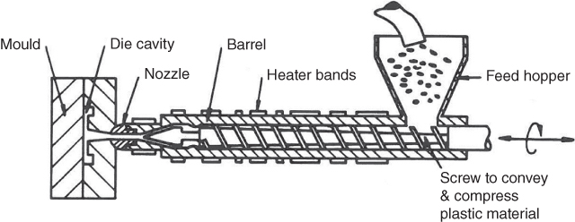
Figure 12.7 A reciprocating screw injection system.
The process is used to produce very large production quantities of components of widely ranging size. Production rates are also high and the components may have an excellent surface finish. With thermoplastic materials there is no waste since the runners and sprues can be regranulated and reused. Disadvantages are that the moulding tools and machines are expensive, closed containers cannot be made without additional assembly work and complex shapes and re‐entrant angles in a design further escalate the tooling costs.
12.7.1 Injection Moulding Tool Design
Due to the importance and widespread use of injection moulding in manufacturing, a little more detail is given here on the design of the moulding tools. The purpose of the tool is first to form the plastic to the desired shape and second to cool the formed product. Figure 12.8 shows a simplified sectional sketch of a two plate injection moulding tool.

Figure 12.8 A two‐plate mould for injection moulding.
The locating ring on the fixed half ensures that the mould is properly located relative to the moulding machine and the guide pins ensure that both mould halves are kept in alignment with each other. The plastic is injected into the fixed half of the mould, the nozzle from the injection moulding machine barrel mating with the tool sprue bush. The other half of the tool is attached to the machine clamping system and can move in the directions shown. When the halves are clamped together the plastic flows into the mould cavities through a central sprue and runner system. The plastic then cools as water flows through internal channels in both mould halves. After the cooling period is completed, the moving half is pulled back. The moulded components, together with sprue and runners, remain with the moving mould half. This is due to the plastic in the sprue having flowed into the notch of the sprue puller shaft and the slight contraction of the cooled plastic also tending to make the components stick to the convex surfaces of the moving mould. As the mould moves back the ejector plate hits against the fixed stop thus causing the ejector pins to move forward relative to the mould; this pushes the moulding forward and off the mould surface. The moulding may then be allowed to fall down into a bin or conveyor or it may be lifted out of the machine by an industrial robot. These handling robots are sometimes equipped to separate the components from the sprue and runner system.
The example discussed refers to a multiple cavity mould. It is also possible to have single cavity moulds that do not require a runner system. The decision whether to use single or multiple cavity moulds is an economic one. Factors that influence this are: number of components to be produced and rate of production – multiple cavity moulds will be best where these factors are high; the precision required in each component; the type of plastic; the capacity of the moulding machine and the position of the mould parting line. The decision on where to place the parting line depends on a number of factors, including the shape of the article and the number of mould cavities. Components with re‐entrant shapes that cannot be released in the normal direction of the mould opening require moulds with more than one parting line. To allow these components to be made facilities such as side or rotating cores may need to be used. Figure 12.9 shows a cam operated side core. As the mould opens right to left the slide rides up the pin shown in the right mould half. This causes the side core to be withdrawn from the moulded component, so allowing a hole to be created at right angles to the normal direction of tool movement.

Figure 12.9 A method for creating a hole at right angles to the direction of travel of the moving half of a moulding tool.
One method of achieving internal screw threads in a component for high volume production is shown in Figure 12.10. As the mould moves linearly over the screw it causes rotation of gear A, which is internally threaded onto the fixed screw. This causes gear B, which is keyed to a shaft with the threaded core at one end, to rotate. The shaft is also threaded and runs in a screw threaded bore of the same pitch as the core. Thus movement of the mould causes rotation and extraction of the core.
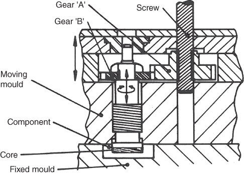
Figure 12.10 A method for creating internal screw threads using a rotating core.
The surface finish of the cavity should be created with great care since every scratch or mark on the surface will be transmitted to the component. Unless a textured surface is desired most mould cavities are highly polished and this is an expensive process.
The designer of the multi‐cavity injection moulding tool must also carefully consider the layout of the sprue runner and gating system. The ‘gate’ is the small aperture where the material from the runner enters the mould cavity; it is also the point where the finished component is broken off from the runner. Figure 12.11 shows an end view of these elements.
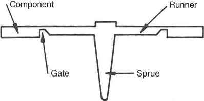
Figure 12.11 A sprue, gate and runner system.
The runner system should be arranged in such a manner as to allow each cavity simultaneously to receive an equal amount of pressurised plastic at each injection. Thus the tool design should provide the shortest possible flow route for the plastic between the sprue and each cavity. Figure 12.12a shows a poor layout since the two cavities nearest the sprue will be filled first; this makes it almost impossible to produce mouldings of uniform quality, since these two cavities will receive extra pressure as the injection continues. Figure 12.12 b shows a better layout, where each cavity receives an equal share of plastic simultaneously; also the cold slug wells at the end of the runners trap partly cooled polymer. A bad cavity layout should always be avoided since it can cause problems such as stress build up in a component, differences in component sizes and mould release problems. It is also important to give close attention to the position and size of the gates. This is because gates determine the flow pattern of the plastic within the cavity and therefore, since plastics evidence molecular orientation in the direction of flow, their positioning and size will also affect the mechanical properties of the finished component.

Figure 12.12 A runner system design for optimum flow: (a) poor and (b) better.
12.7.2 Plastic Component Design for Injection Moulding
Figure 12.13 shows the use of metal inserts in a plastic moulding. These are inserted into the component either by placing them in the moulding tool and allowing the plastic to flow around them before cooling or by press fitting them into the previously moulded component. These allow high strength features to be added where necessary, although very large metal inserts should be avoided as differences in thermal expansion create stresses.

Figure 12.13 Metal inserts in a moulding, the flanges and the knurled head fix or ‘key’ then inserts into the mould.
Just as with any component design functional requirements such as load bearing, resistance to adverse environmental conditions, dimensional constraints, service life, ergonomic and aesthetic specifications must always be met. The designer of injection moulded components must also be familiar with the constraints and advantages of the polymer material being used, the capabilities and limitations of the injection moulding process and the implications of the component design for the mould tool design. Additionally, the plastic product designer should also consider the following points.
- Large flat surfaces should be avoided as they tend to warp. Corrugated, grooved or curved surfaces are better. If flat surfaces must be used warping can be minimised and the surface strengthened by the use of ribs. Care needs to be taken when designing ribs, however, as they can cause light sink marks on the opposite surface to where they are located. This is due to the rib creating an additional mass of material that contracts more than the surrounding thinner material. Sink marks can be minimised by ensuring that rib thicknesses do not exceed two‐thirds the thickness of the main wall and their height does not exceed three times the thickness.
- Corners should be rounded since as well as producing lower stress concentrations than sharp corners they also offer less flow resistance to the injected plastic.
- The component wall thickness should be kept constant as much as possible; where changes in section are necessary, these should be made as gradual as possible.
- Consider that as the plastic in the mould cools it also contracts. Therefore, should the sides of the component be made parallel in the direction of mould opening, it will be evident that the moulding will tend to shrink onto the convex portions of the mould and so make removal difficult. For this reason, a slight taper, called ‘draft’, must always be provided in the component design. This is more apparent on large components as they require greater draft.
- Re‐entrants, or undercuts, should also be avoided or at least kept to a minimum, as they will add extra expense to the manufacture of the injection moulding tool. This is obvious from the earlier section where it was shown that re‐entrants often demand the use of cam operated side cores or complex rotational cores. Even small re‐entrants such as engraved characters should be avoided and replaced with transfers.
Figure 12.14 shows a fictitious component exhibiting poor and improved design. The points mentioned previously are included, along with some additional ones. For example, the rectangular hole in the back wall is expensive to make since it requires a rectangular cam operated side core. A circular opening would be cheaper and changing the opening to a slot completely removes the need for a side core. Large masses of solid plastic, like the pillars in the sketch, cause sink marks – hollows are better. In the component on the right there is a threaded hole that is threaded right up to where the hole meets the surface. This causes a knife edge, which is easily damaged; a recessed thread is better and in this case the thread form has been rounded. In conclusion, as with any design, the simplest component design will be the best one.

Figure 12.14 Some aspects of plastic component design.
Review Questions
- 1 What four factors does an engineer need to consider to ensure that the optimum manufacturing process is selected for making a plastic component?
- 2 Describe the process used to produce continuous lengths of plastic product of constant cross section.
- 3 Describe the blow moulding process, and the type of product to which it is most suited.
- 4 What is the calendering process used for?
- 5 Describe the vacuum forming process and give examples of typical products produced by it.
- 6 Describe the process used to produce disposable plastic bags and refuse sacks.
- 7 Why is the injection moulding process best suited to high volume production?
- 8 Explain how the injection moulding process works (no sketches are necessary).
- 9 Describe the basic construction of an injection moulding tool.
- 10 Why is it advisable to eliminate re‐entrants in an injection moulding design?
- 11 Explain why the designer has to pay particular attention to the manner in which the plastic is transferred from the moulding machine nozzle to the mould cavity.
- 12 Why are ribs necessary in some plastic mouldings and why are their width and height important?
- 13 What is the purpose of ‘draft’ in a plastic component?