
One of the cost effective solution for mobile robot navigation is differential drive systems. It's one of the simplest drive mechanisms for a mobile robot that is mainly indented for indoor navigation. The differential drive robot consists of two wheels mounted on a common axis controlled by two separate motors. There are two supporting wheels called caster wheels. It ensures stability and weight distribution of the robot. The following diagram shows a typical differential drive system:
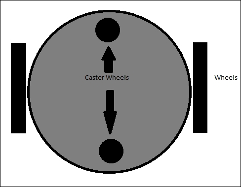
Differential drive system
The next step is to select the mechanical components of this robot drive system, that is, mainly motors, wheels, and robot chassis. Based on the requirements, we will first discuss how to select the motor.
Motors are selected after looking at their specifications. Some of the important parameters for motor selection are torque and RPM. We can compute these values from the given requirements.
Assume the required robot's speed as 0.35 m/s. We saw the speed of robot must be within 0.25 m/s to 1 m/s, as per the requirement. Take the diameter of the wheel as 9 cm because according to the requirement, the ground clearance should be greater than 3 cm. Using the following equation, we can calculate the RPM of motors:
RPM = ((60 * Speed /(3.14 * Diameter of Wheel)
RPM = (60 * 0.35 )/(3.14 * 0.09) = 21 / 0.2826 = 74 RPM
Tip
You can also take a look at http://www.robotshop.com/blog/en/vehicle-speed-rpm-and-wheel-diameter-finder-9786 for computation.
The calculated RPM with 9 cm diameter wheel and 0.35 m/s speed is 74 RPM. We can consider 80 RPM as the standard value.
Let's calculate the torque required to move the robot:
- No of wheels = Four wheels including two caster wheels.
- No of motors = Two.
- Let's assume the coefficient of friction is 0.6 and radius of wheel is 4.5 cm.
- Take total weight of robot = weight of robot + payload = (W = mg) = (~ 100 N + ~ 50 N) W= ~ 150 N, whereas total mass = 15 Kg
- The weight acting on the four wheels can be written as 2 * N1 + 2 * N2 = W, that is, N1 is the weight acting on each caster wheel and N2 on each motor wheel.
- Assume that the robot is stationary. The maximum torque is required when the robot starts moving. It should also overcome friction.
- We can write the frictional force as robot torque = 0 until the robot moves. If we get the robot torque in this condition, we get the maximum torque as follows:
µ * N * r - T = 0, where µ is the coefficient of friction, N is the average weight acting on each wheel, r is the radius of wheels, and T is the torque.
N = W/4 ( assuming that the weight of the robot is equally distributed on all the four wheels)
Therefore, we get:
0.6 * (150/4) * 0.045 - T = 0
Hence, T = 1.0125 N-m or 10.32 Kg-cm
After design, we calculated the following values:
- Motor RPM = 80
- Motor Torque = 10.32 kg-cm
- Wheel diameter = 9 cm
After computing the robot's motor and wheel parameters, we can design the robot chassis or robot body. As required, the robot chassis should have a provision to hold food, it should be able to withstand up to 5 kg payload, the ground clearance of the robot should be greater than 3 cm and it should be low in cost. Apart from this, the robot should have a provision to place electronics components such as Personal Computer (PC), sensors, and battery.
One of the easiest designs to satisfy these requirements is a table-like design. The TurtleBot (http://www.turtlebot.com/) design is a kind of table-like design. It has three layers in the chassis. A robot platform called Roomba is the drive mechanism of this platform. The Roomba platform has motors and sensors inbuilt, so no need to worry about the designing of robot hardware. The following figure shows the TurtleBot robot chassis design:

TurtleBot Robot
We will design a robot similar to TurtleBot with our own moving platform and components. Our design will also have a three layer architecture. Let's see what all tools we want before we start designing.
Before we start designing the robot chassis, we need to know about Computer-aided design (CAD) tools. The popular tools available for CAD are:
- SolidWorks (http://www.solidworks.com/default.htm)
- AutoCAD (http://www.autodesk.com/products/autocad/overview)
- Maya (http://www.autodesk.com/products/maya/overview)
- Inventor (http://www.autodesk.com/products/inventor/overview)
- Google SketchUp (http://www.sketchup.com/)
- Blender (http://www.blender.org/download/)
- LibreCAD (http://librecad.org/cms/home.html)
The chassis design can be designed using any software you are comfortable with. Here, we will demonstrate the 2D model in LibreCAD and the 3D model in Blender. One of the highlights of these applications is that they are free and available for all OS platforms. We will use a 3D mesh viewing tool called MeshLab to view and check the 3D model design and use Ubuntu as the main operating system. Also, we can see the installation procedures of these applications in Ubuntu 14.04.2 to start the designing process. We will provide tutorial links to install applications in other platforms too.