
In Chapter 2, Mechanical Design of a Service Robot, we saw the ChefBot chassis design and now we have got the manufactured parts of this robot. In this chapter, we will see how to assemble this robot using these parts and also the final interfacing of sensors and other electronics components of this robot to Tiva C LaunchPad. We have already discussed interfacing of individual robot components and sensors with Launchpad. In this chapter, we will try to interface the necessary robotic components and sensors of ChefBot and program it in such a way that it will receive the values from all sensors and control the information from the PC. Launchpad will send all sensor values via a serial port to the PC and also receive control information (such as reset command, speed, and so on) from the PC.
After receiving sensor values from the PC, a ROS Python node will receive the serial values and convert it to ROS Topics. There are Python nodes present in the PC that subscribe to the sensor's data and produces odometry. The data from the wheel encoders and IMU values are combined to calculate the odometry of the robot and detect obstacles by subscribing to the ultrasonic sensor and laser scan also, controlling the speed of the wheel motors by using the PID node. This node converts the linear velocity command to differential wheel velocity. After running these nodes, we can run SLAM to map the area and after running SLAM, we can run the AMCL nodes for localization and autonomous navigation.
In the first section of this chapter, Building ChefBot hardware, we will see how to assemble the ChefBot hardware using its body parts and electronics components.
The first section of the robot that needs to be configured is the base plate. The base plate consists of two motors and its wheels, caster wheels, and base plate supports. The following image shows the top and bottom view of the base plate:
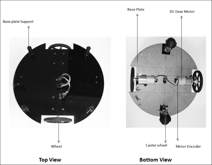
Base plate with motors, wheels, and caster wheels
The base plate has a radius of 15cm and motors with wheels are mounted on the opposite sides of the plate by cutting a section from the base plate. A rubber caster wheel is mounted on the opposite side of the base plate to give the robot good balance and support for the robot. We can either choose ball caster wheels or rubber caster wheels. The wires of the two motors are taken to the top of the base plate through a hole in the center of the base plate. To extend the layers of the robot, we will put base plate supports to connect the next layers. Now, we can see the next layer with the middle plate and connecting tubes. There are hollow tubes, which connect the base plate and the middle plate. A support is provided on the base plate for hollow tubes. The following figure shows the middle plate and connecting tubes:
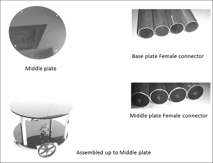
Middle plate with connecting tubes
The connecting tubes will connect the base plate and the middle plate. There are four hollow tubes that connect the base plate to the middle plate. One end of these tubes is hollow, which can fit in the base plate support, and the other end is inserted with a hard plastic with an option to put a screw in the hole. The middle plate has no support except four holes:
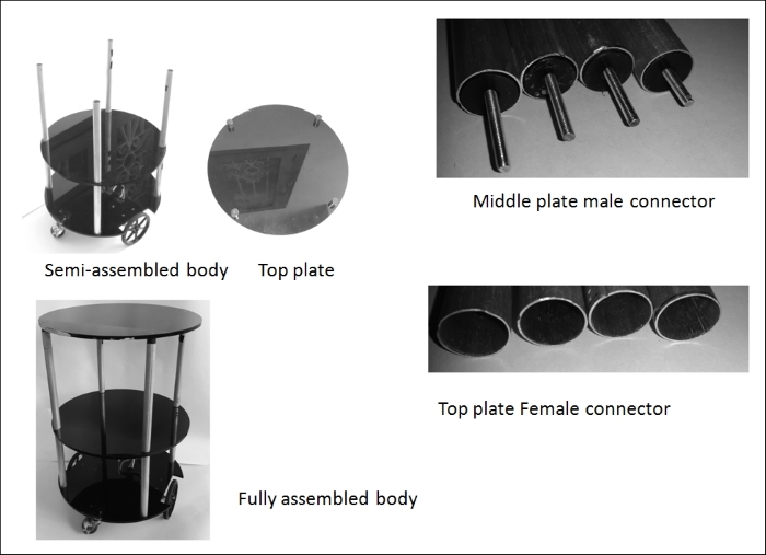
Fully assembled robot body
The middle plate male connector helps to connect the middle plate and the top of the base plate tubes. At the top of the middle plate tubes, we can fit the top plate, which has four supports on the back. We can insert the top plate female connector into the top plate support and this is how we will get the fully assembled body of the robot.
The bottom layer of the robot can be used to put the Printed Circuit Board (PCB) and battery. In the middle layer, we can put Kinect and Intel NUC. We can put a speaker and a mic if needed. We can use the top plate to carry food. The following figure shows the PCB prototype of robot; it consists of Tiva C LaunchPad, a motor driver, level shifters, and provisions to connect two motors, ultrasonic, and IMU:
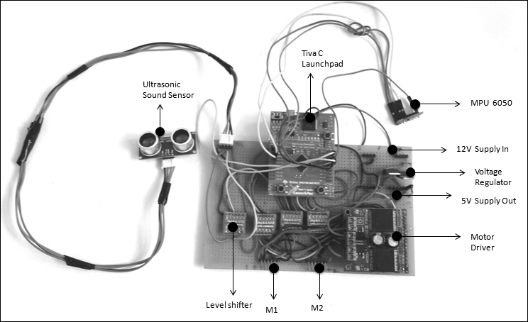
ChefBot PCB prototype
The board is powered with a 12 V battery placed on the base plate. The two motors can be directly connected to the M1 and M2 male connectors. The NUC PC and Kinect are placed on the middle plate. The Launchpad board and Kinect should be connected to the NUC PC via USB. The PC and Kinect are powered using the same 12 V battery itself. We can use a lead-acid or lithium-polymer battery. Here, we are using a lead-acid cell for testing purposes. We will migrate to lithium-polymer for better performance and better backup. The following figure shows the complete assembled diagram of ChefBot:

Fully assembled robot body
After assembling all the parts of the robot, we will start working with the robot software. ChefBot's embedded code and ROS packages are available in GitHub. We can clone the code and start working with the software.