
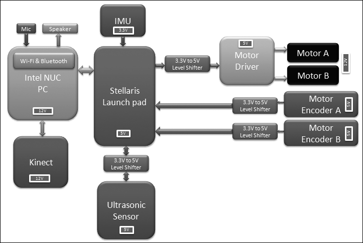
We can explain the working of the ChefBot hardware using the following block diagram. This improved version of our first block diagram mentions the voltage of each component and its interconnection:
The main aim of this chapter was to design the hardware for ChefBot, which included finding the appropriate hardware components and finding the interconnection between each part. The main functionality of this robot is to perform autonomous navigation. The hardware design of robot is optimized for autonomous navigation.
The robot drive is based on differential drive system, which consists of two motors and two wheels. There are caster wheels for supporting the main wheels. These two motors can move the robot in any pose in a 2D plane by adjusting their velocities and direction.
For controlling the velocity and direction of the wheels, we have to interface a motor controller, which can do these functions. The motor driver we chose should able to control two motors at a time and change the direction and speed.
The motor driver pins are interfaced to a microcontroller board called Tiva C LaunchPad, which can send the commands to change the direction and speed of the motor. The motor driver is interfaced into Launchpad with the help of a level shifter. The level shifter is a circuit, which can shift voltage levels from 3.3 V to 5 V and vice versa. We are using a level shifter because the motor driver is operating at 5 V level, but the Launchpad is operating at 3.3 V.
Each motor has a rotation feedback sensor called the encoder, which can be used to estimate the robot's position. The encoders are interfaced into the Launchpad along with the level shifter.
Other sensors interfaced into Launchpad include ultrasonic sound sensor and IMU. Ultrasonic sound sensor can detect objects that are close by, but cannot be detected by the kinect sensor. IMU is used along with the encoders, to get a good robot pose estimation.
All sensor values are received on the Launchpad and sent to PC via USB. The Launchpad runs a firmware code that can receive all sensor values and send to the PC.
The PC is interfaced to kinect, Launchpad, Speaker, and Mic. The PC has ROS running on it and it will receive kinect data and converted to data equivalent to laser scanner. This data can be used to build the map of the environment using SLAM. The speaker/mic is used for communication between the user and robot. The speed commands generated in ROS nodes are sent to Launchpad. Launchpad will then process the speed commands and send appropriate PWM values to the motor driver circuit.
After designing and discussing the working of the robot hardware, we will discuss the detailed interfacing of each component and the firmware coding necessary for the interfacing.