An Inertial Measurement Unit (IMU) is an electronic device that measures velocity, orientation, and gravitational forces using a combination of accelerometers, gyroscopes, and magnetometers. An IMU has a lot of applications in robotics; some of the applications are in balancing of Unmanned Aerial Vehicles (UAVs) and robot navigation.
In this section, we discuss the role of IMU in mobile robot navigation and some of the latest IMUs on the market and its interfacing with Launchpad.
An IMU provides acceleration and orientation relative to inertial space, if you know the initial position, velocity, and orientation, you can calculate the velocity by integrating the sensed acceleration and the second integration gives the position. To get the correct direction of the robot, the orientation of the robot is required; this can be obtained by integrating sensed angular velocity from gyroscope.
The following figure illustrates an inertial navigation system, which will convert IMU values to odometric data:
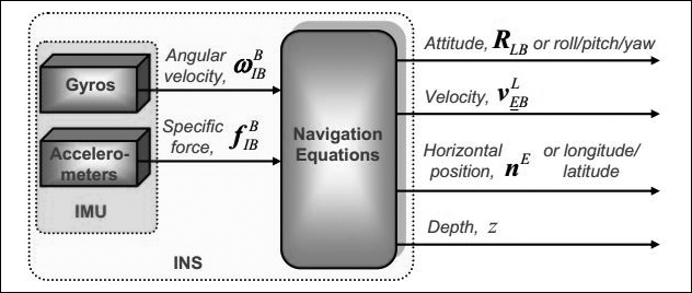
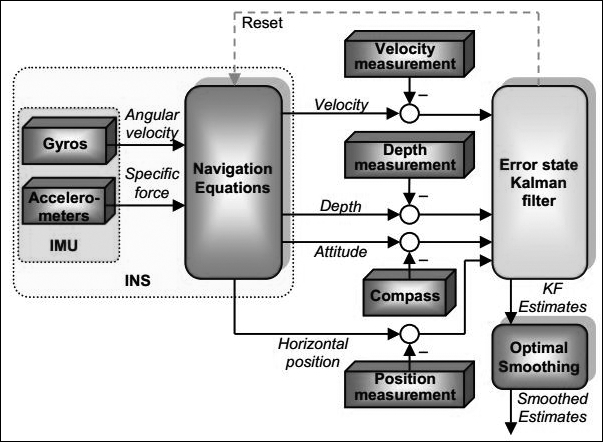
The values we get from the IMU are converted into navigational information using navigation equations and feeding into estimation filters such as the Kalman filter. The Kalman filter is an algorithm that estimates the state of a system from the measured data (http://en.wikipedia.org/wiki/Kalman_filter). The data from Inertial Navigation System (INS) will have some drift because of the error from the accelerometer and gyroscope. To limit the drift, an INS is usually aided by other sensors that provide direct measurements of the integrated quantities. Based on the measurements and sensor error models, the Kalman filter estimates errors in the navigation equations and all the colored sensors' errors. The following figure shows a diagram of an aided inertial navigation system using the Kalman filter:
Along with the motor encoders, the value from the IMU can be taken as the odometer value and it can be used for dead reckoning, the process of finding the current position of a moving object by using a previously determined position.
In the next section, we are going to see one of the most popular IMUs from InvenSense called MPU 6050.
The MPU-6000/MPU-6050 family of parts are the world's first and only 6-axis motion tracking devices designed for the low power, low cost, and high performance requirements of smart phones, tablets, wearable sensors, and robotics.
The MPU-6000/6050 devices combine a 3-axis gyroscope and 3-axis accelerometer on the silicon die together with an onboard digital motion processor capable of processing complex 9-axis motion fusion algorithms. The following figure shows the system diagram of MPU 6050 and breakout of MPU 6050:

The breakout board of MPU 6050 is shown in the following figure and it can be purchased from the following link:
https://www.sparkfun.com/products/110286
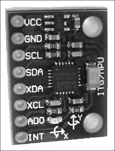
The connection from Launchpad to MPU 6050 is given in the following table. The remaining pins can be left disconnected:
|
Launchpad pins |
MPU6050 pins |
|---|---|
|
+3.3V |
VCC/VDD |
|
GND |
GND |
|
PD0 |
SCL |
|
PD1 |
SDA |
The following figure shows the interfacing diagram of MPU 6050 and Tiva C Launchpad:
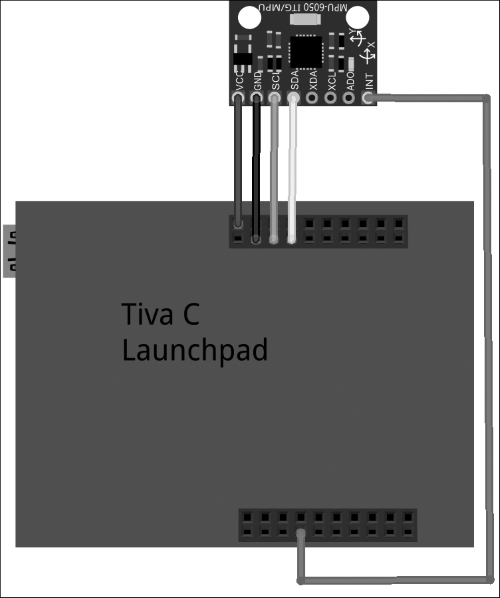
The MPU 6050 and Launchpad communicate using the I2C protocol, the supply voltage is 3.3 Volt and it is taken from Launchpad.
The interfacing code of Energia is discussed in this section. The interfacing code uses the https://github.com/jrowberg/i2cdevlib/zipball/master library for interfacing MPU 6050.
Download the ZIP file from the preceding link and navigate to Preference from File | Preference in Energia, as shown in the following screenshot:
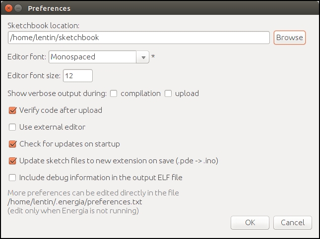
Go to Sketchbook location under Preferences, as seen in the preceding screenshot, and create a folder called libraries. Extract the files inside the Arduino folder inside the ZIP file to the sketchbook/libraries location. The Arduino packages in this repository are also compatible with Launchpad. The extracted files contain the I2Cdev, Wire, and MPU6050 packages that are required for the interfacing of the MPU 6050 sensor. There are other sensors packages that are present in the libraries folder but we are not using them now.
The preceding procedure is done in Ubuntu, but it is the same for Windows and Mac OS X.
This code is used to read the raw value from MPU 6050 to Launchpad, it uses a MPU 6050 third-party library that is compatible with Energia IDE. The following are the explanations of each block of the code.
In this first section of code, we include the necessary headers for interfacing MPU 6050 to Launchpad such as 12C, Wire and the MPU6050 library and create an object of MPU6050 with the name accelgyro. The MPU6050.h library contains a class named MPU6050 to send and receive data to and from the sensor:
#include "Wire.h"

#include "I2Cdev.h"
#include "MPU6050.h"

MPU6050 accelgyro;
In the following section, we start the I2C and serial communication to communicate with MPU 6050 and print sensor values through the serial port. The serial communication baud rate is 115200 and Setup_MPU6050() is the custom function to initialize the MPU 6050 communication:
void setup()
{

  //Init Serial port with 115200 buad rate
  Serial.begin(115200);
  Setup_MPU6050();
}
The following section is the definition of the Setup_MPU6050() function. The Wire library allows you to communicate with the I2C devices. MPU 6050 can communicate using I2C. The Wire.begin()function will start the I2C communication between MPU 6050 and Launchpad; also, it will initialize the MPU 6050 device using the initialize() method defined in the MPU6050 class. If everything is successful, it will print connection successful, otherwise it will print connection failed:
void Setup_MPU6050()
{
   Wire.begin();

      // initialize device
    Serial.println("Initializing I2C devices...");
    accelgyro.initialize();

    // verify connection
    Serial.println("Testing device connections...");
    Serial.println(accelgyro.testConnection() ? "MPU6050 connection successful" : "MPU6050 connection failed");
}
The following code is the loop() function, which continuously reads the sensor value and prints its values through the serial port: The Update_MPU6050() custom function is responsible for printing the updated value from MPU 6050:
void loop()
{

   //Update MPU 6050
    Update_MPU6050();

}
The definition of Update_MPU6050() is given as follows. It declares six variables to handle the accelerometer and gyroscope value in 3-axis. The getMotion6() function in the MPU 6050 class is responsible for reading the new values from the sensor. After reading, it will print via the serial port:
void Update_MPU6050()
{
int16_t ax, ay, az;
int16_t gx, gy, gz;
// read raw accel/gyro measurements from device
accelgyro.getMotion6(&ax, &ay, &az, &gx, &gy, &gz);
// display tab-separated accel/gyro x/y/z values
Serial.print("i");Serial.print(" ");
Serial.print(ax); Serial.print(" ");
Serial.print(ay); Serial.print(" ");
Serial.print(az); Serial.print(" ");
Serial.print(gx); Serial.print(" ");
Serial.print(gy); Serial.print(" ");
Serial.println(gz);
Serial.print("
");
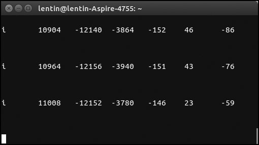
}The output from the serial monitor is shown here:
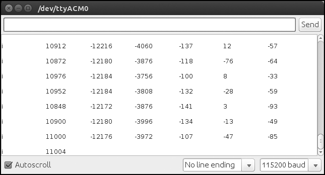
We can read these values using the python code that we used for ultrasonic. The following is the screenshot of the terminal when we run the python script: