
In this chapter, we will discuss the calibration and testing of ChefBot that is necessary before deploying the robot in the work place. The testing can be done using the GUI that we built in the previous chapter. Before the test run, we can calibrate the sensors and address the issues in the ChefBot hardware and software. In the testing procedure, we can build a map of a hotel kind of arrangement and navigate on the map using ROS on ChefBot. We can also see ways to improve accuracy and upgrade the ChefBot prototype in future.
First, we will look at the calibration of sensors such as Kinect, Quadrature encoder, and IMU to improve the accuracy of the robot.
Kinect calibration is required to improve the accuracy of the Kinect data. In this robot, Kinect is used instead of a laser scanner. We can generate data equivalent to that provided by laser scanner by converting Point Cloud data, using a depth image to laser scanner converter package in ROS. This converted data may not be as precise as an actual laser scanner, so in effect, the error from the converted laser scanner can affect robot mapping, navigation, and localization. To reduce the errors to some extent, we can do a calibration prior to our application. Kinect can even work on factory settings without being calibrated, each device has its own camera parameters and these can change from device to device. Some of the camera parameters are focal length, format size principle point, and lens distortion. When we perform camera calibration, we are able to adjust these values.
One of the calibrations used in Kinect is intrinsic calibration. Some of the intrinsic parameters are focal length and distortion model. Using intrinsic calibration, we can correct these values of IR (depth) and RGB camera intrinsic parameters.
Let's see how to perform Kinect intrinsic calibration using ROS and Python.
Before calibrating Kinect using ROS, ensure that the OpenNI driver packages and camera calibration packages of ROS are installed. If they are not installed, we can install them using the following command:
$ sudo apt-get install ros-indigo-openni-launch ros-indigo-camera-calibration
Before the calibration, print an 8 x 6 checkerboard of 0.108 meter in length. We will get a standard 8 x 6 checkerboard file from the following link:
http://wiki.ros.org/camera_calibration/Tutorials/MonocularCalibration
Follow the procedure to calibrate the RGB camera in Kinect:
- Start the OpenNI driver using the following command. This will start Kinect RGB and depth stream images:
$ roslaunch openni_launch openni.launch - After launching drivers, run the calibrator code available on the
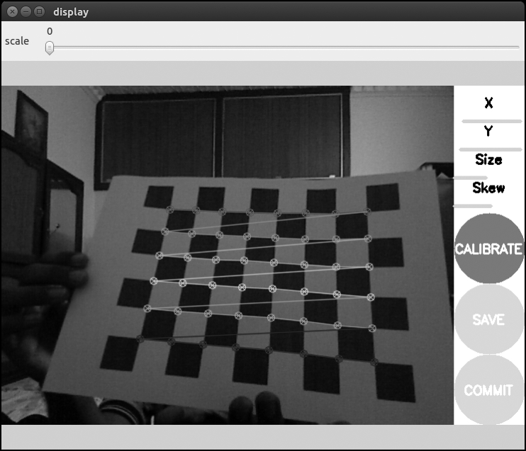
camera_calibrationpackage. Thecameracalibrator.pyfile is the node that performs camera calibration. We have to specify the RGB raw image topic, camera topic, size of the checkerboard and size of the square that we are using. Simply run the calibrator node by using following command:$ rosrun camera_calibration cameracalibrator.py image:=/camera/rgb/image_raw camera:=/camera/rgb --size 8x6 --square 0.108 - The above command will open the following window:

- Assuming that you have a printed checkerboard and you hold it in your hand and show it on the Kinect RGB camera, you can see patterns getting detected, as in the preceeding figure. If it is detected properly, then move the checkerboard to the left, right, top, and bottom of the camera view, as shown in the following figure. There are four bars on the right; the X and Y bar indicate the amount of data collected in the x and y direction and the Size and Skew bars indicate the samples of images, that are, towards/away from the camera and tilted up/down respectively.
- At each step, hold the checkerboard still until the image gets highlighted by the detection pattern in the calibration window. The necessary checkerboard position is shown as follows:

- When we move the checkerboard around the RGB camera, the size of the bars increase and when the calibration program gets enough samples for calibration, the CALIBRATE button will become active.
- We click on the CALIBRATE button to start calibration. The calibration process can take about a minute. The calibration window may be non-responsive for some time, but it will be ready eventually.
After the calibration process is complete, we can see the calibration results in the terminal and the corrected image will be shown in the calibration window.
A successful calibration will result in a rectified image and a failed calibration usually results in a blank or unrecognizable image.
After calibration, we can use the slider on the top of the calibration window to adjust the size of the rectified image. The scale value will show as zero the rectified image, and some pixels in the original image will be discarded. A scale of 1.0 means we can see the original image and the rectified image has black borders where there are no input pixels in the original image.
If you are satisfied with the calibration, click on the COMMIT button to send the calibration parameters to the camera for permanent storage. The GUI exits and you should see writing calibration data to ... in the console.
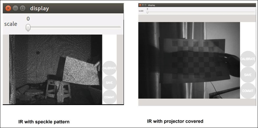
Kinect can detect the depth of the environment using an IR camera and an IR speckle projector, which can perform the same function as a stereo camera. We can calibrate the depth image that we got from Kinect using the checkerboard that we used for the RGB camera calibration.
The difficulty in calibrating a depth image is that the speckle pattern on the depth image can block the accurate detection of the corners of the checkerboard. One possible solution is to cover the IR projector and illuminate it with another IR source such as sunlight, incandescent lamp, and so on. The first figure shows the checkerboard with the speckle pattern and the second figure shows the depth image illuminated by an incandescent lamp and covering the speckle IR projector.
The Python script used for the RGB camera can be used for depth calibration. The following command is used to calibrate the IR camera. Run the calibrator node using the depth image topic; we are using the 8 x 6 checkerboard with a size of 0.108 meter, as shown in the following example:
$ rosrun camera_calibration cameracalibrator.py image:=/camera/ir/image_raw camera:=/camera/ir --size 8x6 --square 0.108
The ROS driver for Kinect cannot stream both IR and RGB images. It will decide which of the two to stream, based on the amount of subscribers. It is best to not run any ROS nodes during the calibration of the depth image, which subscribe RGB frames.
Repeat the same movements of the RGB camera calibration in depth camera too. After calibration, we can press the COMMIT button to save the calibration values to a file. When we press the COMMIT button, the values will be sent to the openni_camera driver package in a form of ROS service call. When openni_camera receives the camera parameters, it will store them to a file with the help of an ROS package called camera_info_manager. The camera_info_manager package can handle these parameters and store them in some location. The default location of intrinsic parameters is $HOME/.ros/camera_info/NAME.yaml and the name of file contains the camera name and device serial number. This file can be moved to any public location we want. The name of the files of RGB and depth calibration will look like rgb_A00362903124106A.yaml and depth_A00362903124106A.yaml.
The content of the RGB camera calibration file is given as follows:
image_width: 640
image_height: 480
camera_name: rgb_A00362903124106A
camera_matrix:
  rows: 3
  cols: 3
  data: [543.275251827696, 0, 286.5024846235134, 0, 544.9622371717294, 270.5536535568697, 0, 0, 1]
distortion_model: plumb_bob
distortion_coefficients:
  rows: 1
  cols: 5
  data: [0.1236660642773772, -0.2974236496563437, 0.008147821573873778, -0.03185623828978901, 0]
rectification_matrix:
  rows: 3
  cols: 3
  data: [1, 0, 0, 0, 1, 0, 0, 0, 1]
projection_matrix:
  rows: 3
  cols: 4
  data: [531.7443237304688, 0, 263.0477918357592, 0, 0, 559.802490234375, 274.1133349321171, 0, 0, 0, 1, 0]
If the files are placed in the default location, the OpenNI driver can automatically take the calibration files from this location. If we want to save them in some other location, we have to use the launch file section given in the following code and mention the path of the camera calibration files as arguments of openni.launch:
<launch>
<!-- Include official launch file and specify camera_info urls -->
 <include file="$(find openni_launch)/launch/openni.launch">
   <!-- provide arguments to that launch file -->
   <arg name="rgb_camera_info_url"
        value="file:///public/path/rgb_ A00362903124106A.yaml" />
   <arg name="depth_camera_info_url"
       value="file:///public/path/depth_ A00362903124106A.yaml" />
 </include>
</launch>