
Calibration is required in odometry to reduce navigational errors. The main parameter needed to calibrate this is the measure of Distance per encoder ticks of the wheels. It is the distance traversed by the robot wheel after during each encoder tick.
The wheel base is the distance between the two differential drive wheels. Distance per encoder ticks is the distance traversed by the wheel on each encoder count. We can calibrate the robot by monitoring encoder counts of each wheel by driving for a fixed distance. The average of these counts is divided by the total distance traveled to get a starting value for the encoder click, which happens per millimeter. The encoder manufacturer may mention an encoder count in one revolution, but in a practical scenario, there will be changes in it.
To calibrate the robot, drive the robot for a fixed distance and note down the encoder counts in the left and right motor. The following equation can give an average count per millimeter:
Counts per millimeter = (left counts + right counts)/2)/ total millimeter traveled
An error from the wheel odometry can result in accumulation of errors in the position of the robot. The odometry value can change when the wheel slips on the ground or moves on an uneven terrain. The odometry error generated while the robot rotates can cause severe errors in the robot's final position. For example, in a 10 meter trip of robot, if both wheels slip by 1 centimeter, it can cause 0.1 percent errors in the total distance and the robot will arrive 1 cm short of its destination.
However, if the slip between two wheels is 1 centimeter, it can cause more errors than the first case that we discussed. This can result in a large error in both X and Y coordinates.
Assume that the robot wheel base is 10 centimeter and a slip of 1 centimeter between two wheels can result in 0.1 radian error, which is about 5.72 degrees. Given here is the equation to find the heading error:
heading error = (left - right) / Wheel base
= (0.01 / 0.1)
= 0.1 radians * (180 / PI) = ~ 5.72 degrees
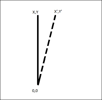
We can find the final position of the robot after 10 meters with a heading error of 0.1 radian, as shown here:
X' = 10 * sin (5.72) = ~ 1 meter
Y' = 10 * cos(5.72) = 9.9 meter
From these calculations, we know that a heading error of 0.1 radian causes a shift of 1 meter in the x direction from the destination position. The illustration of this error is given as follows:
From this analysis, we understood that a small error in θ produces large errors in X and Y. The main error affects the orientation of the robot rather than the distance traveled. There are some methods to reduce this error. These are mentioned in the following section.
From the above analysis, it can be seen that the most important error in the robot's position calculation is the error in heading, the θ calculation. Some of the methods to reduce θ errors are as follows:
- Digital compass: We can deploy a digital compass in the robot to get the heading of the robot and thereby reduce the robot heading error. Digital compass can be used alone but it may encounter problems such as if there is any local magnetic anomaly, it can make a big noise in the reading. Also, the compass must be perfectly inclined to the robot's surface; if the surface is uneven, there will be errors in the compass readings.
- Digital gyroscope: The digital gyroscope provides the rate of change of the angle or angular velocity. If we know the angular velocity, we can find the angle by integrating the values over a period of time. We can find the angular velocity of the robot using gyro; but the gyro value can make errors too. If a robot has to cover a great distance, the error computing from gyro will increase, so gyro can only be used if the robot covers a short distance. If the robot covers a great distance, we can use the combination of a gyroscope and a compass.
- Gyro-corrected compass: In this method, we incorporate the gyro and compass in to a single unit, so that one sensor can correct the other. Combining these sensor values using a Kalman filter can give better heading values for the robot.
In the ChefBot prototype, we are using Gyro alone. In future upgrades, we will replace gyro with the combination of gyro and compass.
We are using an IMU called MPU-6050 by Invense to get the heading of the robot. The following section explains a simple calibration method to reduce the offset of MPU 6050. Here are the procedures to calibrate the sensor.