
The wheel encoder is a sensor attached to the motor to sense the number of rotations of the wheel. If we know the number of rotations, we can compute the displacement, velocity, acceleration, and angle of the wheel.
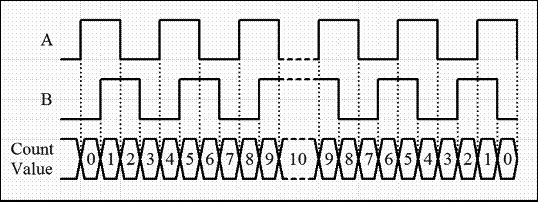
For this robot, we have chosen a motor with an in-built encoder. This encoder is a quadrature type, which can sense both the direction and speed of the motor. Encoders use different types of sensors, such as optical and hall sensors, to detect these parameters. This encoder uses Hall effect to sense the rotation. The quadrature encoder has two channels, namely Channel A and Channel B. Each channel will generate digital signals with ninety degree phase shift. The following figure shows the wave form of a typical quadrature encoder:

Quadrature encoder waveforms
If the motor rotates clockwise, Channel A will lead Channel B, and if the motor rotates counterclockwise, Channel B will lead Channel A. This reading will be useful to sense the direction of rotation of the motor. The following section discusses how we can translate the encoder output to useful measurements like displacement and velocity.
Encoder data is a two channel pulse out with 90 degree out of phase. Using this data, we can find the direction of rotation and how many times the motor has rotated, and thereby find the displacement and velocity.
Some of the terms that specify encoder resolution are pulses per revolution (PPR) or lines per revolution (LPR) and counts per revolution (CPR). PPR specifies how many electrical pulses (0 to 1 transitions) there will be during one revolution of a motor's final shaft. Some manufacturers use the name CPR instead of PPR. Because each pulse will contain two edges (rising and falling) and there are two pulse channels (A and B) with a 90 degree phase shift, the total number of edges will be four times the number of PPR. Most quadrature receivers use the so called 4X decoding to count all the edges from an encoder's A and B channels yielding 4X resolution compared to the raw PPR value.
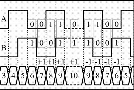
In our motor, Pololu specifies that the CPR is 64 for the motor shaft, which corresponds to 8400 CPR of the gearbox's output shaft. In effect, we get 8400 counts from the gearbox output shaft when the motor's final shaft completes one revolution. The following figure shows how we can compute the count from the encoder pulses:
Encoder waveform with count waveform
In this encoder specification, they give the count per revolution; it is calculated by the encoder channel edge transitions. One pulse of an encoder channel corresponds to four counts. So to get 8400 counts in our motor, the PPR will be 8400 / 4 = 2100. From the preceding figure, we will be able to calculate the number of counts in one revolution, but we also need to sense the direction of the movement. This is because irrespective of whether the robot moves forward or backward, the counts that we get will be same; so sensing the direction is important in order to decode the signal. The following figure shows how we can decode the encoder pulses:
If we observe the code pattern, we can understand that it follows the 2-bit Gray code. A Gray code is encoding of numbers, such that adjacent numbers have a single digit differing by 1. Gray codes (http://en.wikipedia.org/wiki/Gray_code) are commonly used in rotary encoders for efficient coding.
We can predict the direction of rotation of a motor by state transitions. The state transition table is given in the following figure:
|
State |
Clockwise transition |
Counterclockwise transition |
|---|---|---|
|
0,0 |
0,1 to 0,0 |
1,0 to 0,0 |
|
1,0 |
0,0 to 1,0 |
1,1 to 1,0 |
|
1,1 |
1,0 to 1,1 |
0,1 to 1,1 |
|
0,1 |
1,1 to 0,1 |
0,0 to 0,1 |
It will be more convenient if we represent it in a state transition diagram:
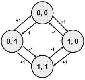
After getting this Gray code, we can process the pulses using a microcontroller. The channel pins of the motor have to be connected to the interrupt pins of the microcontroller. So when the channel has edge transitions, it will generate an interrupt or trigger in the pins, and if any interrupts arrives in that pin, an interrupt service routine or simply a function will be executed inside the microcontroller program. It can read the current state of the two pins. According to the current state of pins and previous values, we can determine the direction of rotation and can decide whether we have to increment or decrement the count. This is the basic logic of encoder handling.
After getting the count, we can calculate the angle of rotation (in degrees) using Angle = (Count Value / CPR) * 360. Here, if we substitute CPR with 8400, the equation becomes Angle = 0.04285 * Count Value, that is, for turning one degree, 24 counts have to be received or 6 encoded channel pulses have to come.
The following figure shows the interfacing circuit of one motor encoder with Tiva C LaunchPad:

Interfacing Motor encoder with Tiva C Launchpad
The maximum level of output pulse is between 0 V to 5 V from the encoder. In this case, we can directly interface the encoder with Launchpad because it can receive input of up to 5 V, or we can use a 3.3 V to 5 V level shifter like we used for motor driver interfacing earlier.
In the next section, we will write a code in Energia to test the quadrature encoder signal. We need to check whether we get a proper count from encoder.
This code will print the count of the left and right motor encoder via a serial port. The two encoders are in 2X decoding scheme, so we will get 4200 CPR. In the first section of the code, we are defining pins for two channel outputs of two encoders and we are declaring the count variable for two encoders. The encoder variable uses a volatile keyword before the variable data type.
The main use of volatile is that the variable with volatile keyword will be stored in the RAM, whereas normal variables are in CPU registers. Encoder values will change very quickly, so using an ordinary variable will not be accurate. In order to get accuracy, we will use volatile for encoder variables, as follows:
//Encoder pins definition

// Left encoder

#define Left_Encoder_PinA 31
#define Left_Encoder_PinB 32

volatile long Left_Encoder_Ticks = 0;

//Variable to read current state of left encoder pin
volatile bool LeftEncoderBSet;

//Right Encoder

#define Right_Encoder_PinA 33
#define Right_Encoder_PinB 34
volatile long Right_Encoder_Ticks = 0;
//Variable to read current state of right encoder pin
volatile bool RightEncoderBSet;
The following code snippet is the definition of the setup() function. In wiring language, setup() is a built-in function used for initialization and for one-time execution of variables and functions. Inside setup(), we initialize the serial data communication with a baud rate of 115200 and call a user-defined function SetupEncoders() to initialize pins of the encoders. The serial data communication is mainly done to check the encoder count via the serial terminal.
void setup()
{
    //Init Serial port with 115200 buad rate
    Serial.begin(115200);
  SetupEncoders();
}
The definition of SetupEncoders() is given in the code that follows. To receive the encoder pulse, we need two pins in Launchpad as the input. Configure the encoder pins to Launchpad as the input and activate its pull-up resistor. The attachInterrupt () function will configure one of the encoder pins as an interrupt. The attachInterrupt () function has three arguments. First argument is the pin number, second argument is the Interrupt Service Routine (ISR), and the third argument is the interrupt condition, that is, the condition in which the interrupt has to fire ISR. In this code, we are configuring PinA of the left and right encoder pins as the interrupt; it calls the ISR when there is a rise in the pulse.
void SetupEncoders()
{
  // Quadrature encoders
  // Left encoder
  pinMode(Left_Encoder_PinA, INPUT_PULLUP);
  // sets pin A as input
  pinMode(Left_Encoder_PinB, INPUT_PULLUP);
  // sets pin B as input
  attachInterrupt(Left_Encoder_PinA, do_Left_Encoder, RISING);

  // Right encoder
  pinMode(Right_Encoder_PinA, INPUT_PULLUP);
  // sets pin A as input
  pinMode(Right_Encoder_PinB, INPUT_PULLUP);
  // sets pin B as input

  attachInterrupt(Right_Encoder_PinA, do_Right_Encoder, RISING);
}
The following code is the built-in loop() function in wiring language. The loop() function is an infinite loop where we put our main code. In this code, we call the Update_Encoders() function to print the encoder value continuously through serial terminal.
void loop()
{
  Update_Encoders();
}
The following code is the function definition of the Update_Encoders() function. It prints two encoder values in a line with a starting character "e", and the values are separated by tab spaces. The Serial.print() function is a built-in function that will print the character/string given as the argument.
void Update_Encoders()
{
  Serial.print("e");
  Serial.print("	");
  Serial.print(Left_Encoder_Ticks);
  Serial.print("	");
  Serial.print(Right_Encoder_Ticks);
  Serial.print("
");
 }
The following code is the ISR definition of the left and right encoders. When a rising edge is detected on each of the pins, one of the ISRs will be called. The current interrupt pins are PinA of each of the encoders. After getting the interrupt, we can assume that the rising PinA has a higher value state, so there is no need to read that pin. Read PinB of both the encoders and store the pin state to LeftEncoderBSet or RightEncoderBSet. The current state is compared to the previous state of PinB and can detect the direction and decide whether the count has to be incremented or decremented according to the state transition table.
void do_Left_Encoder()
{
LeftEncoderBSet = digitalRead(Left_Encoder_PinB);
// read the input pin
Left_Encoder_Ticks -= LeftEncoderBSet ? -1 : +1;
}
void do_Right_Encoder()
{
RightEncoderBSet = digitalRead(Right_Encoder_PinB);
// read the input pin
Right_Encoder_Ticks += RightEncoderBSet ? -1 : +1;
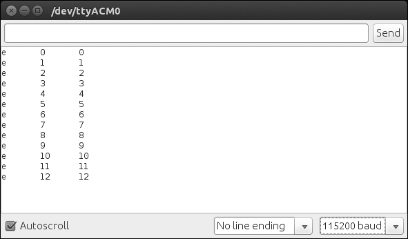
}Upload the sketch and view the output using the serial monitor in Energia. Navigate to Tools | Serial monitor. Move the two motors manually and you can see the count changing. Set the baud rate in the serial monitor, which is the same as initialized in the code; in this case, it is 115200.
The output will look like this:
If we want to upgrade the robot to high accuracy and payload, we have to think about high quality actuators such as Dynamixel. Dynamixels are intelligent actuators, which have in-built PID control and monitoring of the servo and encoder parameters, such as torque, position, and so on.