
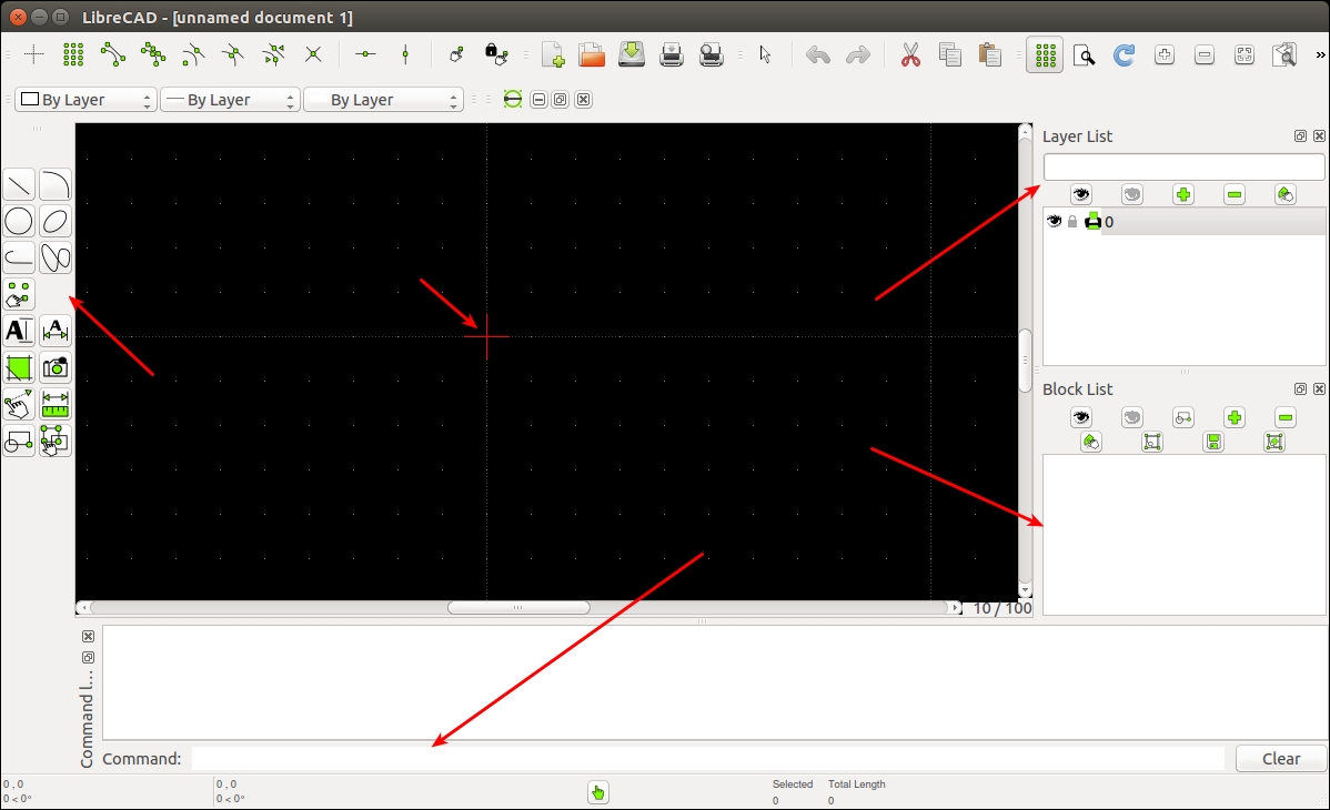
We can take a look at the basic interface of LibreCAD. The following screenshot shows the interface of LibreCAD:
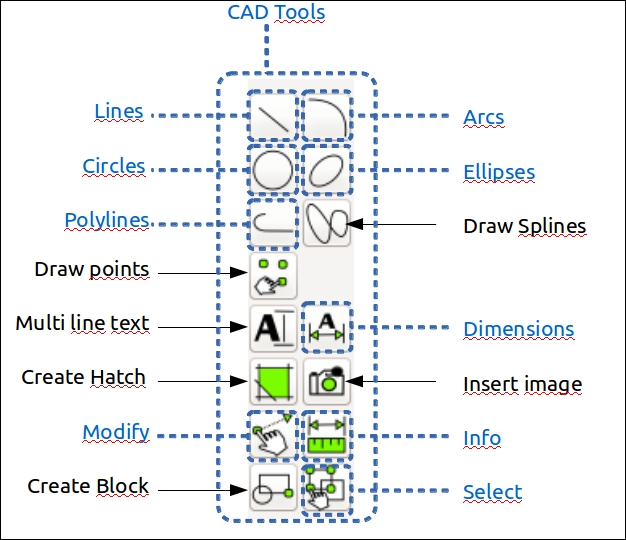
A CAD toolbar has the necessary components to draw a model. The following screenshot shows the detailed overview of the CAD toolbar:
A detailed description of LibreCAD tools is available at the following link:
http://wiki.librecad.org/index.php/LibreCAD_users_Manual.
- Command Box: This is used to draw figures by only using commands. We can draw diagrams without touching any toolbar. A detailed explanation about the usage of the command box can be found at:
http://wiki.librecad.org/index.php/A_short_manual_for_use_from_the_command_line.
- Layer List: This will have layers used in the current drawing. A basic concept in computer-aided drafting is the use of layers to organize a drawing. A detailed explanation of layers can be found at:
- Block: This is a group of entities and can be inserted in the same drawing more than once with different attributes at different locations, different scale, and rotation angle. A detailed explanation of Blocks can be found at the following link:
- Absolute Zero: This is the origin of the drawing (0,0).
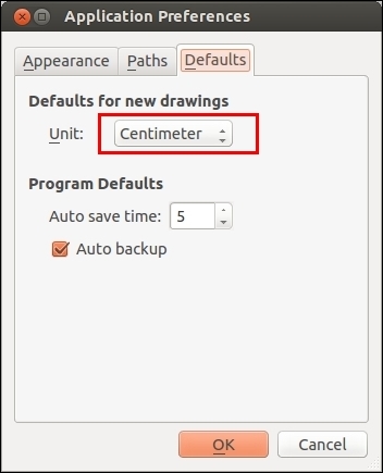
Now, start sketching by setting the unit of drawing. Set the drawing unit to centimeter. Open LibreCAD, navigate to Edit | Application Preference. Set Unit as Centimeters, as shown in the following screenshot:
Let's start with the base plate design. The base plate has provisions to connect motors, place battery, and control board.
The following figure shows the robot's base plate. This plate provides provisions for two motors for differential drive and each caster wheel on the front and back of the base plate. Motors are mentioned as M1 and M2 in the diagram and caster wheels are represented as C1 and C2. It also holds four poles to connect to the next plates. Poles are represented as P1-1, P1-2, P1-3, and P1-4. The screws are indicated as S and we will use the same screws here. There is a hole at the center to bring the wires from the motor to the top of the plate. The plate is cut on the left-hand side and the right-hand side so that the wheels can be attached to the motor. The distance from the center to caster wheels is mentioned as 12.5 cm and the distance from the center to motors is mentioned as 5.5 cm. The center of poles is at 9 cm in length and 9 cm in height from the center. The holes of all the plates follow the same dimensions:
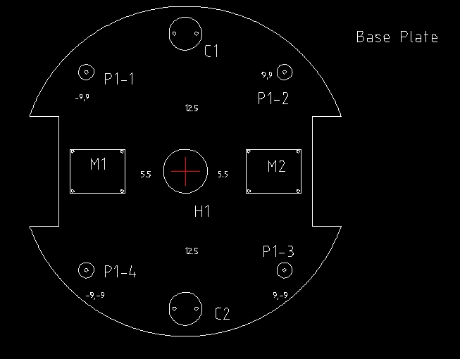
The dimensions are not marked on the diagram; instead, it's mentioned in the following table:
|
Parts |
Dimension(cm)(Length x Height)( radius) |
|---|---|
|
M1 and M2 |
5 x 4 |
|
C1 and C2 |
Radius = 1.5 |
|
S(Screw) |
0.15 |
|
P1-1, P1-2, P1-3, P1-4 |
Outer radius 0.7, Height 3.5 |
|
Left and Right Wheel Sections |
2.5 x 10 |
|
Base plate |
Radius = 15 |
We can discuss more about motor dimensions and clamp dimensions later.
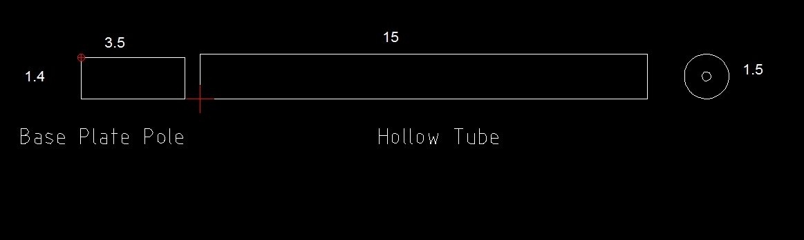
The base plate has four poles to extend to the next layer. The poles are 3.5 cm in length with a radius of 0.7 cm. We can extend to the next plate by attaching hollow tubes to the poles. At the top of the hollow tube, we will insert a hard plastic to make a screw hole. This hole will be useful to extend to the top layer. The base plate pole and the hollow tubes on each pole is shown in the following figure. Each hollow tube a radius of 0.75 cm and length of 15 cm:
We have to decide the diameter of the wheel and compute motor requirements. Here, we are using a typical motor and wheel that we can use if the design is successful:
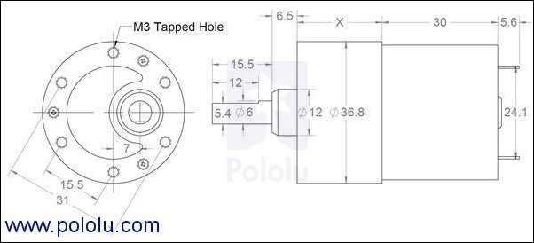
The motor design can vary according to the motor selection; if necessary, this motor can be taken as per the design and can be changed after simulation. The X value in the motor diagram can vary according to the speed and torque of motors. This is the gear assembly of motor.
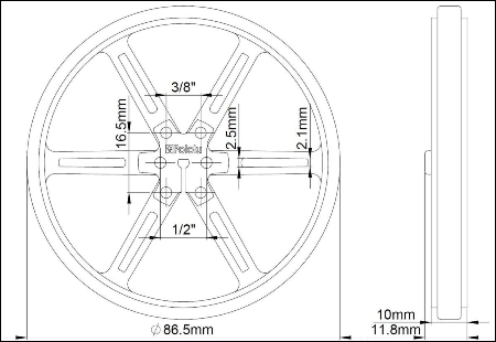
The following figure shows a typical wheel that we can use with a diameter of 90 cm. The wheel with a diameter of 86.5 mm will become 90 mm after placing the grip.
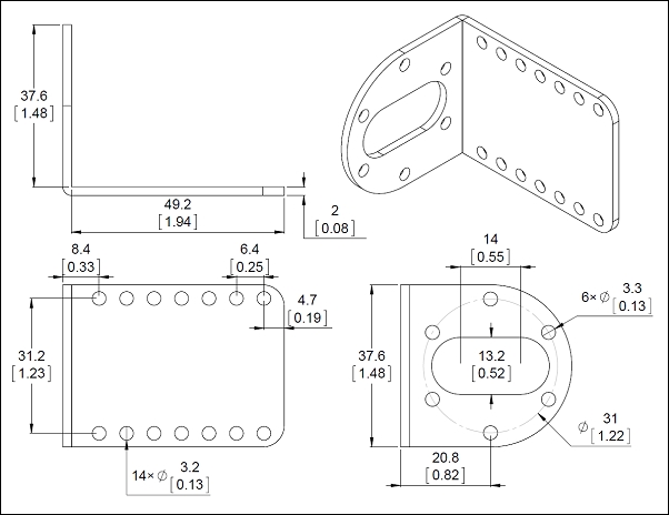
The motor needs to be mounted on the base plate; to mount, we need a clamp which can be screwed onto the plate and also connect the motor to the clamp. The following figure shows a typical clamp we can use for this purpose. It's an L-shaped clamp, with which we can mount the motor on one side and fit another side to the plate:
Caster wheels need not have a special design; we can use any caster wheel that can touch the ground similar to the wheels. The following link has a collection of caster wheels that we can use for this design:
The dimension of this plate is same as the base plate, and the screw size is also similar:
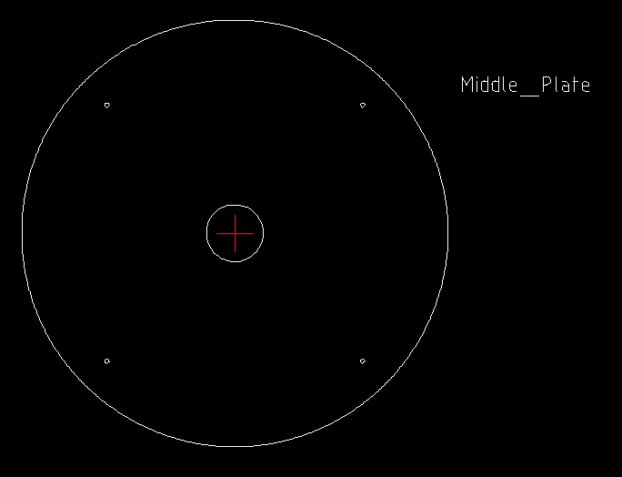
The middle plate can be held above the hollow tubes from the base plate. This arrangement is connected using another hollow tube that extends from the middle plate. The tube from the middle plate will have a screw at the bottom to fix the tube from the base plate to the middle plate, and a hollow end to connect the top plate. The top and side view of the tube extending from the middle plate is shown in the following figure:
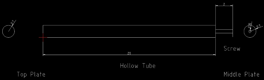
This tube will connect the middle plate to the base plate and at the same time provide a provision to connect the top plate.
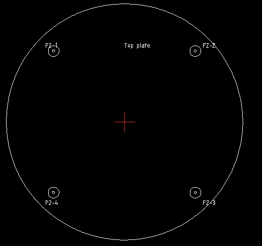
The top plate is similar to other plates; it has four small poles of 3 cm, similar to the base plate. These poles can be placed on the hollow tubes from the middle plate. The four poles are connected to the plate, shown as follows:
After the top plate design, the robot chassis design is almost finished; let's see the 3D model building of this robot using Blender. The 3D model is built for simulation purpose and the 2D design we build is mainly for manufacturing purpose.