
The robot's movement is controlled by two Direct Current (DC) gear motors with an encoder. The two motors are driven using a motor driver. The motor driver is interfaced into an embedded controller board, which will send commands to the motor driver to control the motor movements. The encoder of the motor is interfaced into the controller board for counting the number of rotations of the motor shaft. This data is the odometry data from the robot. There are ultrasonic sensors, which are interfaced into the controller board for sensing the obstacles and measuring the distance from the obstacles. There is an IMU sensor to improve odometry calculation. The embedded controller board is interfaced into a PC, which does all the high-end processing in the robot. Vision and sound sensors are interfaced into the PC and Wi-Fi is attached for remote operations.
Each block of the robot is explained in the following diagram:
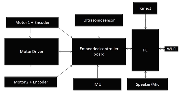
Robot Hardware block Diagram
The robot that we are going to design is a differential drive robot with two wheels, so we require two motors for its locomotion. Each motor consists of quadrature encoders (http://letsmakerobots.com/node/24031) to get the motor rotation feedback.
The quadrature encoder will give a feedback of the rotation of the motor as square pulses; we can decode the pulse to get the number of ticks of the encoder, which can be used for feedback. If we know the wheel diameter and the number of ticks of the motor, we can compute the displacement and the angle of the robot that traversed. This computation is very useful for navigation of the robot.
From the simulation, we got an idea about the robot parameters. On the simulation parameters, we mentioned that the motor torque needed to drive the robot is 18 kg-cm, but the calculated torque is less than this; we are selecting a high torque motor for better performance. One of the economical motors that we might consider using is from Pololu. We can select a high torque DC gear motor with an encoder working at 12 V DC and having speed of 80 RPM according to our design. We are choosing the following motor for the drive system in this robot:
http://www.pololu.com/product/1447
The following figure shows the image of the selected motor for this robot. The motor comes with an integrated quadrature encoder with a resolution of 64 counts per revolution of the motor shaft, which corresponds to 8400 counts per revolution of the gearbox's output shaft.
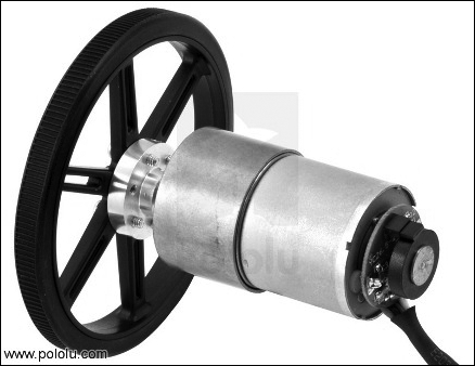
DC Gear motor with encoder and wheel
This motor has 6 pins with different colors. The pin description of this motor is given in the following table:
|
Color |
Function |
|---|---|
|
Red |
Motor power (connects to one motor terminal) |
|
Black |
Motor power(connects to the other motor terminal) |
|
Green |
Encoder GND |
|
Blue |
Encoder Vcc ( 3.5 V - 20 V) |
|
Yellow |
Encoder A output |
|
White |
Encoder B output |
According to our design, we chose a wheel diameter of 90 mm. Pololu provides a 90 mm wheel, which is available at http://www.pololu.com/product/1439. The preceding figure showed the motor assembled with this wheel.
The other connectors needed to connect the motors and wheels together are available as follows:
- The mounting hub required to mount the wheel to the motor shaft is available at http://www.pololu.com/product/1083
- The L- bracket for the motor to mount on robot chassis is available at http://www.pololu.com/product/1084
A motor driver or motor controller is a circuit that can control the speed of the motor. Controlling motors means that we can control the voltage across the motor and can also control the direction and speed of the motor. Motors can rotate clockwise or counter clockwise, if we change the polarity of motor terminal.
H-bridge circuits are commonly used in motor controllers. H-bridge is an electronic circuit that can apply voltage in either direction of load. It has high current handling properties and can change the direction of current flow.
The following screenshot shows a basic H-bridge circuit using switches:
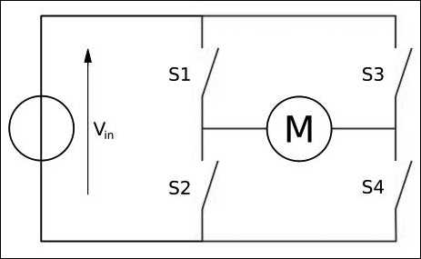
H Bridge circuit
The direction of the motor, depending on the four switches, is given as follows:
|
S1 |
S2 |
S3 |
S4 |
Result |
|---|---|---|---|---|
|
1 |
0 |
0 |
1 |
Motor moves right |
|
0 |
1 |
1 |
0 |
Motor moves left |
|
0 |
0 |
0 |
0 |
Motor free runs |
|
0 |
1 |
0 |
1 |
Motor brakes |
|
1 |
0 |
1 |
0 |
Motor brakes |
|
1 |
1 |
0 |
0 |
Motor shoots through |
|
0 |
0 |
1 |
1 |
Motor shoots through |
|
1 |
1 |
1 |
1 |
Motor shoots through |
We have seen the basics of an H-bridge circuit on the motor driver circuit. Now, we can select one of the motor drivers for our application and discuss how it works.
There are some motor drivers available with Pololu, which are compatible with the selected motor. The following figure shows one of the motor drivers that we will use in our robot:
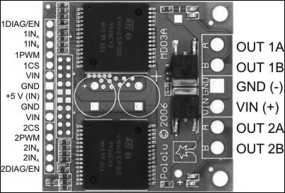
Dual VNH2SP30 Motor Driver Carrier MD03A
This motor driver is available at http://www.pololu.com/product/708.
This driver can drive two motors with a combined maximum current rating of 30 A, and contains two integrated IC for driving each of the motors. The pin description of this driver is given in the upcoming sections.
The following pins are the input pins of the motor driver, by which we can control mainly the motor speed and direction:
|
Pin Name |
Function |
|---|---|
|
1DIAG/EN, 2DIAG/EN |
This monitors the fault condition of motor driver 1 and 2. In normal operation, it will remain disconnected. |
|
1INa, 1INb, 2INa, 2INb |
These pins will control the direction of motor 1 and 2 in the following manner:
|
|
1PWM, 2PWM |
This will control the speed of motor 1 and 2 by rapidly turning them on and off. |
|
1CS, 2CS |
This is the current sensing pin for each motor. |
Controller boards are typically I/O boards, which can send control signals in the form of digital pulses to the H-Bridge/motor driver board and can receive inputs from sensors such as ultrasonic and IR sensors. We can also interface motor encoders to the control board for the motor feedback.
The main functionalities of Launchpad in this robot are:
- Interfacing the motor driver and encoder
- Interfacing the ultrasonic sound sensor
- Sending and receiving sensor values to PC and from PC
We will deal with I/O boards and interfacing with different components in the upcoming chapters. Some of the popular I/O boards are Arduino (arduino.cc) and Tiva C LaunchPad (http://www.ti.com/tool/EK-TM4C123GXL) by Texas Instruments. We are selecting Tiva C LaunchPad over Arduino because of following factors:
- Tiva C LaunchPad has a microcontroller based on 32-bit ARM Cortex-M4 with 256 KB Flash memory, 32 KB SRAM, and 80 MHz operation; however, most of the Arduino boards run below this specification.
- Outstanding processing performance, combined with fast interrupt handling.
- 12 Timers.
- 16 PWM Outputs.
- Two quadrature encoder inputs.
- Eight Universal Asynchronous Receiver/Transmitter (UART).
- 5 V tolerant General-Purpose Input/Output (GPIO).
- Low cost and size compared to Arduino boards.
- Easy programmable interface IDE called Energia (http://energia.nu/). The code written in Energia is Arduino board compatible.
The following image shows the Texas Instrument's Tiva C LaunchPad:
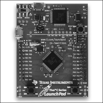
Tiva C Launchpad
The pinout of Texas Instrument Launchpad series is given at http://energia.nu/pin-maps/guide_stellarislaunchpad/. This pinout is compatible with all the Launchpad series. This is also used while programming in Energia IDE.
Ultrasonic sensors are also called ping sensors, and are mainly used to measure the robot's distance from an object. The main application of ping sensors is to avoid obstacles. The ultrasonic sensor sends high frequency sound waves and evaluates the echoes that are received from the object. The sensor will calculate the delay between sending and receiving the echo, and from that, determine its distance from an object.
In our robot, collision-free navigation is an important aspect, otherwise there will be damage to the robot. You will see a figure showing an ultrasonic sensor in the next section. This sensor can be employed on the sides of a robot to detect collision on the sides and back of the robot. The kinect is also mainly used for obstacle detection and collision avoidance. The accuracy of kinect can only be expected from 0.8 m, so that distance in between 0.8 m can be detected using ultrasonic sensor. It is actually an add-on to our robot for increasing collision avoidance and detection.
One of the popular and cheap ultrasonic sensors available is HC-SR04. We are selecting this sensor for our robot because of the following factors:
- Range of detection is from 2 cm to 4 m
- Working voltage is 5 V
- Working current is very low typically 15 mA
We can use this sensor for accurate detection of obstacles; it also works with 5 V. Here is the image of HC-SR04 and its pinout:
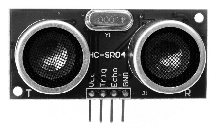
Ultrasonic sound sensor
The pins and description are given as follows:
|
Pins |
Function |
|---|---|
|
Vcc, GND |
These are the supply pins of ultrasonic sensor. Normally, we need to apply 5 V for a normal operation. |
|
Trig |
This is the input pin of the sensor. We need to apply a pulse with a particular duration to this pin to send the ultrasonic sound waves. |
|
Echo |
This is the output pin of the sensor. It will generate a pulse on this pin with a time duration, according to the delay in receiving the triggered pulse. |
We will use Inertial Measurement Unit (IMU) in this robot to get a good estimate of the odometry value and the robot pose. The odometry values computed from the encoder alone may not be sufficient for efficient navigation, it could contain errors. To compensate for errors during the robot's movement, we will use IMU in this robot. We are selecting MPU 6050 for IMU because of following reasons:
- In MPU 6050, the accelerometer and gyroscope are integrated on a single chip
- It provides high accuracy and sensitivity
- There is provision to interface magnetometer for better IMU performance
- The breakout board of MPU 6050 is very cheap
- The MPU 6050 can directly interface to Launchpad, both are 3.3 V compatible and software libraries are also available for easier interfacing
The following figure shows the breakout board of MPU 6050:
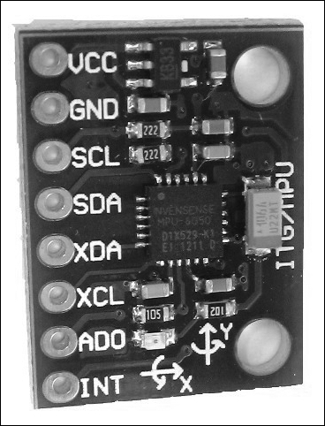
The pins and their descriptions are given as follows:
We can purchase the breakout board from https://www.sparkfun.com/products/11028.
Kinect is a 3D vision sensor, mainly used in 3D vision application and motion gaming. We are using kinect for 3D vision. Using kinect, the robot will get the 3D image of its surroundings. The 3D images are converted to finer points called point cloud. The point cloud data will have all 3D parameters of the surrounding.
The main use of kinect on the robot is to mock the functionality of a laser scanner. The laser scanner data is essential for an algorithm called SLAM, used for building a map of the environment. The laser scanner is a very costly device, so instead of buying an expensive laser scanner, we can convert a kinect into a virtual laser scanner. Another alternative to kinect is Asus Xtion PRO (http://www.asus.com/Multimedia/Xtion_PRO/). This will support the same software written for kinect. The point cloud to laser data conversion is done on the software, so no need to change the hardware parts. After generating a map of the environment, the robot can navigate its surroundings.
The following image shows the various parts of a kinect sensor:
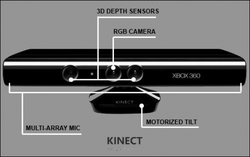
Kinect
The kinect mainly has an IR camera and IR projector and also has an RGB camera. The IR camera and projector generates the 3D point cloud of the surroundings. It also has a mic array and motorized tilt for moving the kinect up and down.
We can purchase kinect from http://www.amazon.co.uk/Xbox-360-Kinect-Sensor-Adventures/dp/B0036DDW2G.
The robot is mainly controlled by its navigational algorithm that is running on its PC. We can choose a laptop or mini PC or netbook for the processing. Recently, Intel launched a minicomputer called Intel Next Unit of Computing (NUC). It has an ultra small form factor (small size), is lightweight, and has a good computing processor with Intel Celeron, Core i3, or Core i5. It can support upto 16 GB of RAM and has integrated Wi-Fi/Bluetooth. We are choosing Intel NUC because of its performance, ultra small form factor, and lightweight. We are not going for a popular board, such as Raspberry Pi (http://www.raspberrypi.org/) or BeagleBone (http://beagleboard.org/) because we require high computing power in this case, which cannot be provided by these boards.
The NUC we are using is Intel DN2820FYKH. Here are the specifications of this computer:
- Intel Celeron Dual Core processor with 2.39 GHz
- 4 GB RAM
- 500 GB hard disk
- Intel integrated graphics
- Headphone/microphone jack
- 12 V supply
The following image shows the Intel NUC minicomputer:
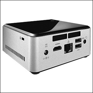
Intel NUC DN2820FYKH
We can purchase NUC from http://goo.gl/Quzi7a.
The main function of the robot is autonomous navigation. We are adding an additional feature in which the robot can interact with users through speech. The robot can be given commands using voice and can speak to the user using a text to speech (TTS) engine, which can convert text to speech format. A microphone and speakers are essential for this application. There is no particular selection for this hardware. If the speaker and mic are USB compatible, then it will be great. Another alternative is a Bluetooth headset.
One of the important hardware component is the power supply. We saw in the specification that the robot has to work for more than 1 hour; it will be good if the supply voltage of the battery is common to the components. Also, if the size and weight of the battery is less, it will not affect the robot's payload. Another concern is that the maximum current needed for the entire circuit should not exceed the battery's maximum current, which it can source. The maximum voltage and current distribution of each part of the circuit is as follows:
|
Components |
Maximum current (Ampere) |
|---|---|
|
Intel NUC PC |
12 V, 3 A |
|
Kinect |
12 V, 1 A |
|
Motors |
12 V,0.7 A |
|
Motor driver, Ultrasonic sensor, IMU, Speakers |
5 V, < 0.5 A |
To meet these specifications, we are selecting a 12V, 9 AH Li-Polymer battery for our operation. This battery can also source maximum current up to 5 Ampere.
The following image shows our selected battery for this robot:
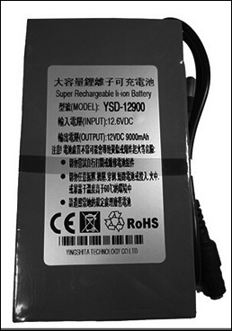
We can buy the following battery from http://goo.gl/Clzk6I.