
In this section, you'll build projects that you'll wear as a part of your clothing or accessories. Hopefully, this will expand your concept of where you might be able to creatively use Arduino. Let's get started.
The project for this section is a wearable pin that will indicate your direction through a circular LED set. You could wear this type of device on an armband, like a watch, or pin it on your clothes, just to prove that you are not only technically savvy, but have a keen fashion sense. However, as we are talking about robots, you can actually add these wearables to your robot to give the outside world some indication of what the robot is thinking.
To start, you'll need an Arduino board built for fashion. For this project, you'll use the FLORA. This was introduced in Chapter 1, Powering on Arduino. It has a different form factor; it looks like the following image:
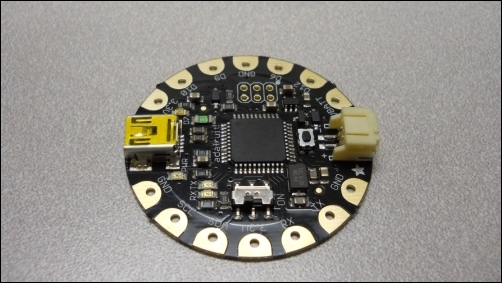
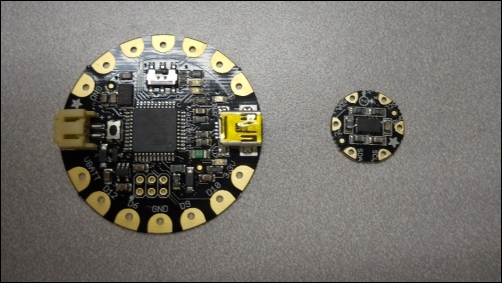
The Arduino FLORA unit is interesting for a couple of reasons. Its form factor is certainly one of them, but it is also designed to go into wearable applications and is even washable (but don't try it with the battery attached). In this particular application, you'll be using the FLORA with two of its accessories to build a device that can indicate direction. To do this, you'll need both a way of finding the direction as well as a way of indicating direction. To find direction, you'll add the FLORA Accelerometer/Compass module, the LSM303, available at www.adafruit.com. The following is an image of this device, with the FLORA on the right-hand side for size comparison:
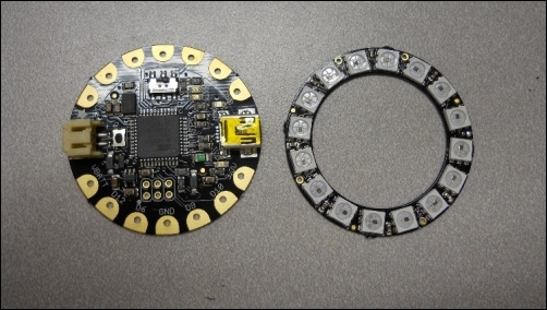
This module was specifically designed to be used with the FLORA processor. For the indicator, you'll use the NeoPixel ring, which is also available at www.adafruit.com. This ring provides lighting in different colors. The following is an image of the ring, again with the FLORA on the right-hand side for size comparison:
Perform the following steps to get the NeoPixel ring working with the FLORA:
- First, make the following connections between the FLORA and the NeoPixel ring:
Flora pin
NeoPixel ring pin
VBATT
Power 5 V DC
GND
Power signal ground
D6
Data input
- Now, you'll need to download, if you have not already done so, the Arduino IDE designed to work with the FLORA. You can download it from learn.adafruit.com/getting-started-with-flora/download-software.
- After you have done this, you'll need to download the library from github.com/adafruit/Adafruit_NeoPixel.
- Install this into the
librarydirectory of your Adafruit Arduino IDE. - Now, bring up a simple example program by navigating to Examples | Adafruit_Neopixel | strandtest.
Upload this program, and your NeoPixel ring should start displaying various colors. Now that the ring is working, let's add a digital compass to the project. Here are the steps:
- You'll need to connect the digital compass to the FLORA. The following are the connections:
FLORA pin
LSM303
3.3 V
3 V
GND
Po
SDA
SDA
SCL
SCL
- Now that you have made the connections, you'll need to download the library that supports the LSM303 device from github.com/adafruit/Adafruit_LSM303DLHC.
- You'll also need to download and install Adafruit's sensor library from github.com/adafruit/Adafruit_Sensor.
- When you have installed these, upload the digital compass example program by navigating to Examples | Adafruit_LSM303DLHC | magsensor. When you open the Serial Monitor tab, you should see the following screenshot:

The device is reporting information on the direction. A more useful way to look at this data is provided by Adafruit at learn.adafruit.com/lsm303-accelerometer-slash-compass-breakout/coding. At the bottom of this page is a listing that will show the actual direction when the device is held flat. Unfortunately, you'll need to make just a couple of changes because of the updates to the drivers. The following is the new sketch:
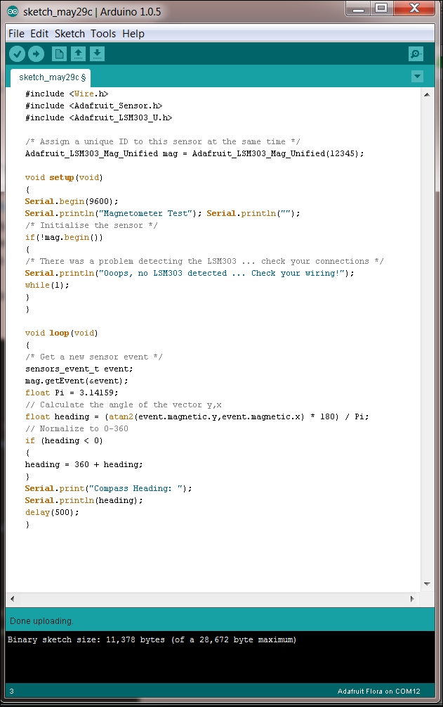
Specifically, you'll need to change #include <Adafruit_LSM303.h> to #include <Adafruit_LSM303_U.h>. You'll also need to change Adafruit_LSM303_Mag mag = Adafruit_LSM303_Mag(12345); to Adafruit_LSM303_Mag_Unified mag = Adafruit_LSM303_Mag_Unified(12345);.
When you upload and run this program, and open the Serial Monitor tab, you should see the following screenshot:
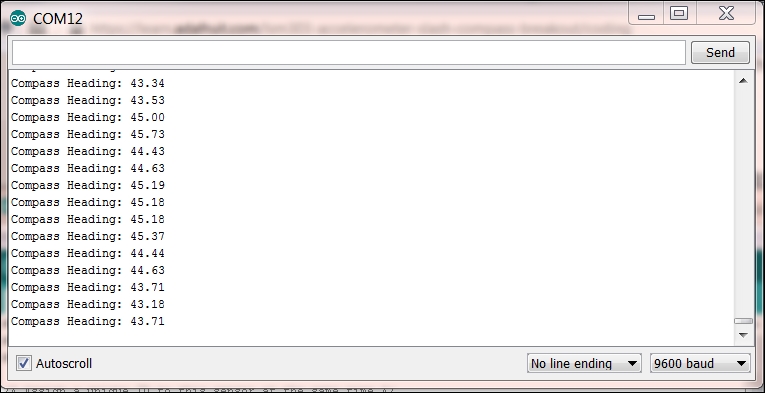
Now, you have access to Compass Heading. The final step is to merge the NeoPixel code with the Compass Heading code. The following is a simple example that changes color based on the direction:

And there you have it! As you move your device around, you should see the color of the ring change. The only step left is to package the device. You can put the pieces together on a button or a write strap, or connect them directly to your robot, and your LED will give you an indication of the direction in which the robot is heading. You could easily change the sensor to one that measures temperature, distance, or light; the possibilities are almost endless.