In this chapter, we will cover:
- Point sprites with the geometry shader
- Drawing a wireframe on top of a shaded mesh
- Drawing silhouette lines using the geometry shader
- Tessellating a curve
- Tessellating a 2D quad
- Tessellating a 3D surface
- Tessellating based on depth
Tessellation and geometry shaders are relatively new additions to the OpenGL pipeline, and provide programmers with additional ways to modify geometry as it progresses through the shader pipeline. Geometry shaders can be used to add, modify, or delete geometry, and tessellation shaders can be configured to automatically generate geometry at various levels of detail and to facilitate interpolation based on arbitrary input (patches).
In this chapter, we'll look at several examples of geometry and tessellation shaders in various contexts. However, before we get into the recipes, let's investigate how all of this fits together.
The following diagram shows a simplified view of the shader pipeline when the shader program includes geometry and tessellation shaders:
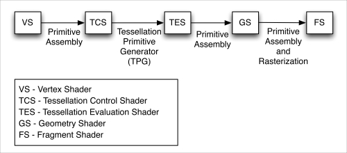
The tessellation portion of the shader pipeline includes two stages: the tessellation control shader (TCS), and the tessellation evaluation shader (TES). The geometry shader follows the tessellation stages and precedes the fragment shader. The tessellation shader and geometry shader are optional; however, when a shader program includes a tessellation or geometry shader, a vertex shader must be included.
Note
Other than the preceding requirement, all shaders are optional. However, when a shader program does not include a vertex or fragment shader, the results are undefined. When using a geometry shader, there is no requirement that you also include a tessellation shader and vice versa. It is rare to have a shader program that does not include at least a fragment shader and a vertex shader.
The geometry shader (GS) is designed to execute once for each primitive. It has access to all of the vertices of the primitive, as well as the values of any input variables associated with each vertex. In other words, if a previous stage (such as the vertex shader) provides an output variable, the geometry shader has access to the value of that variable for all vertices in the primitive. As a result, the input variables within the geometry shader are always arrays.
The geometry shader can output zero, one, or more primitives. Those primitives need not be of the same kind that were received by the geometry shader. However, the GS can only output one primitive type. For example, a GS could receive a triangle, and output several line segments as a line strip. Or a GS could receive a triangle and output zero or many triangles as a triangle strip.
This enables the GS to act in many different ways. A GS could be responsible for culling (removing) geometry based on some criteria, such as visibility based on occlusions. It could generate additional geometry to augment the shape of the object being rendered. The GS could simply compute additional information about the primitive and pass the primitive along unchanged. Or the GS could produce primitives that are entirely different from the input geometry.
The functionality of the GS is centered around the two built-in functions, EmitVertex and EndPrimitive. These two functions allow the GS to send multiple vertices and primitives down the pipeline. The GS defines the output variables for a particular vertex, and then calls EmitVertex. After that, the GS can proceed to re-define the output variables for the next vertex, call EmitVertex again, and so on. After emitting all of the vertices for the primitive, the GS can call EndPrimitive to let the OpenGL system know that all the vertices of the primitive have been emitted. The EndPrimitive function is implicitly called when the GS finishes execution. If a GS does not call EmitVertex at all, then the input primitive is effectively dropped (it is not rendered).
In the following recipes, we'll examine a few examples of the geometry shader. In the Point sprites with the geometry shader recipe, we'll see an example where the input primitive type is entirely different than the output type. In the Drawing a wireframe on top of a shaded mesh recipe, we'll pass the geometry along unchanged, but also produce some additional information about the primitive to help in drawing wireframe lines. In the Drawing silhouette lines using the geometry shader recipe, we'll see an example where the GS passes along the input primitive, but generates additional primitives as well.
When the tessellation shaders are active, we can only render one kind of primitive: the patch (GL_PATCHES). Rendering any other kind of primitive (such as triangles, or lines) while a tessellation shader is active is an error. The patch primitive is an arbitrary "chunk" of geometry (or any information) that is completely defined by the programmer. It has no geometrical interpretation beyond how it is interpreted within the TCS and TES. The number of vertices within the patch primitive is also configurable. The maximum number of vertices per patch is implementation dependent, and can be queried via the following command:
glGetIntegerv(GL_MAX_PATCH_VERTICES, &maxVerts);
We can define the number of vertices per patch with the following function:
glPatchParameteri( GL_PATCH_VERTICES, numPatchVerts );
A very common application of this is when the patch primitive consists of a set of control points that define an interpolated surface or curve (such as a Bezier curve or surface). However, there is no reason why the information within the patch primitive couldn't be used for other purposes.
The patch primitive is never actually rendered, instead, it is used as additional information for the TCS and TES. The primitives that actually make their way further down the pipeline are created by the tessellation primitive generator (TPG), which lies between the TCS and the TES. Think of the tessellation primitive generator as a configurable engine that produces primitives based on a set of standard tessellation algorithms. The TCS and the TES have access to the entire input patch, but have fundamentally different responsibilities. The TCS is responsible for setting up the TPG, defining how the primitives should be generated by the TPG (how many and what algorithm to use), and producing per-vertex output attributes. The TES has the job of determining the position (and any other information) of each vertex of the primitives that are produced by the TPG. For example, the TCS might tell the TPG to generate a line strip consisting of 100 line segments, and the TES is responsible for determining the position of each vertex of those 100 line segments. The TES would likely make use of the information within the entire patch primitive in order to do so.
The TCS is executed once for each vertex in the output patch (specified in the TCS code). It can compute additional information about the patch and pass it along to the TES using output variables. However, the most important task of the TCS is to tell the TPG how many primitives it should produce. It does this by defining tessellation levels via the gl_TessLevelInner and gl_TessLevelOuter arrays. These arrays define the granularity of the tessellation produced by the TPG.
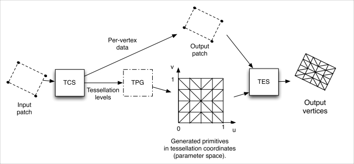
The TPG generates primitives based on a particular algorithm (quads, isolines, or triangles). Each algorithm produces primitives in a slightly different fashion, and we will see examples of isolines and quads in the recipes in this chapter. Each vertex of the generated primitives is associated with a position in parameter space (u, v, w). Each coordinate of this position is a number that can range from zero to one. This coordinate can be used for evaluating the location of the vertex, often by interpolation of the patch primitive's vertices. The primitive generation algorithms produce vertices (and the associated parametric coordinates) in a slightly different fashion. The tessellation algorithms for quads and isolines make use of only the first two parametric coordinates: u and v. The following diagram illustrates the process for an input and output patch consisting of four vertices. In the diagram, the TPG uses the quad tessellation algorithm with inner and outer tessellation levels set at four.
The TES is executed once for each parameter-space vertex that is generated by the TPG. Somewhat strangely, the TES is actually the shader that defines the algorithm used by the TPG. It does so via its input layout qualifier. As stated above, its main responsibility is to determine the position of the vertex (possibly along with other information, such as normal vector and texture coordinate). Typically, the TES uses the parametric coordinate (u,v) provided by the TPG along with the positions of all of the input patch vertices to do so. For example, when drawing a curve, the patch might consist of four vertices, which are the control points for the curve. The TPG would then generate 101 vertices to create a line strip (if the tessellation level was set to 100), and each vertex might have a u coordinate that ranged appropriately between zero and one. The TES would then use that u coordinate along with the positions of the four patch vertices to determine the position of the vertex associated with the shader's execution.
If all of this seems confusing, start with the Tessellating a curve recipe, and work your way through the following recipes.
In the Tessellating a curve recipe, we'll go through a basic example where we use tessellation shaders to draw a Bezier curve with four control points. In the Tessellating a 2D quad recipe, we'll try to understand how the quad tessellation algorithm works by rendering a simple quad and visualizing the triangles produced by the TPG. In the Tessellating a 3D surface recipe, we'll use quad tessellation to render a 3D Bezier surface. Finally, in the Tessellating based on depth recipe, we'll see how the tessellation shaders make it easy to implement level-of-detail (LOD) algorithms.