
When a cartoon or hand-drawn effect is desired, we often want to draw black outlines around the edges of a model and along ridges or creases (silhouette lines). In this recipe, we'll discuss one technique for doing this using the geometry shader, to produce the additional geometry for the silhouette lines. The geometry shader will approximate these lines by generating small, skinny quads aligned with the edges that make up the silhouette of the object.
The following figure shows the ogre mesh with black silhouette lines generated by the geometry shader. The lines are made up of small quads that are aligned with certain mesh edges.

The technique shown in this recipe is based on a technique published in a recent blog post by Philip Rideout (prideout.net/blog/?p=54). His implementation uses two passes (base geometry and silhouette), and includes many optimizations, such as anti-aliasing and custom depth testing (with g-buffers). To keep things simple, as our main goal is to demonstrate the features of the geometry shader, we'll implement the technique using a single pass without anti-aliasing or custom depth testing. If you are interested in adding these additional features, refer to Philip's excellent blog posting.
One of the most important features of the geometry shader is that it allows us to provide additional vertex information beyond just the primitive being rendered. When geometry shaders were introduced into OpenGL, several additional primitive rendering modes were also introduced. These "adjacency" modes allow additional vertex data to be associated with each primitive. Typically, this additional information is related to the nearby primitives within a mesh, but there is no requirement that this be the case (we could actually use the additional information for other purposes if desired). The following list includes the adjacency modes along with a short description:
GL_LINES_ADJACENCY: This mode defines lines with adjacent vertices (four vertices per line segment)GL_LINE_STRIP_ADJACENCY: This mode defines a line strip with adjacent vertices (for n lines, there are n+3 vertices)GL_TRIANGLES_ADJACENCY: This mode defines triangles along with vertices of adjacent triangles (six vertices per primitive)GL_TRIANGLE_STRIP_ADJACENCY: This mode defines a triangle strip along with vertices of adjacent triangles (for n triangles, there are 2(n+2) vertices provided)
For full details on each of these modes, check out the official OpenGL documentation. In this recipe, we'll use the GL_TRIANGLES_ADJACENCY mode to provide information about adjacent triangles in our mesh. With this mode, we provide six vertices per primitive. The following diagram illustrates the locations of these vertices:
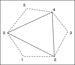
In the preceding diagram, the solid line represents the triangle itself, and the dotted lines represent adjacent triangles. The first, third, and fifth vertices (0, 2, and 4) make up the triangle itself. The second, fourth, and sixth are vertices that make up the adjacent triangles.
Mesh data is not usually provided in this form, so we need to preprocess our mesh to include the additional vertex information. Typically, this only means expanding the element index array by a factor of two. The position, normal, and texture coordinate arrays can remain unchanged.
When a mesh is rendered with adjacency information, the geometry shader has access to all six vertices associated with a particular triangle. We can then use the adjacent triangles to determine whether or not a triangle edge is part of the silhouette of the object. The basic assumption is that an edge is a silhouette edge if the triangle is front facing and the corresponding adjacent triangle is not front facing.
We can determine whether or not a triangle is front facing within the geometry shader by computing the triangle's normal vector (using a cross product). If we are working within eye coordinates (or clip coordinates), the z coordinate of the normal vector will be positive for front facing triangles. Therefore, we only need to compute the z coordinate of the normal vector, which should save a few cycles. For a triangle with vertices A, B, and C, the z coordinate of the normal vector is given by the following equation:
Once we determine which edges are silhouette edges, the geometry shader will produce additional skinny quads aligned with the silhouette edge. These quads, taken together, will make up the desired dark lines (refer to the preceding figure). After generating all the silhouette quads, the geometry shader will output the original triangle.
In order to render the mesh in a single pass with appropriate shading for the base mesh, and no shading for the silhouette lines, we'll use an additional output variable. This variable will let the fragment shader know when we are rendering the base mesh and when we are rendering the silhouette edge.
Set up your mesh data so that adjacency information is included. As just mentioned, this probably requires expanding the element index array to include the additional information. This can be done by passing through your mesh and looking for shared edges. Due to space limitations, we won't go through the details here, but the blog post mentioned some time back has some information about how this might be done. Also, the source code for this example contains a simple (albeit not very efficient) technique.
The important uniform variables for this example are as follows:
EdgeWidth: This is the width of the silhouette edge in clip (normalized device) coordinatesPctExtend: This is a percentage to extend the quads beyond the edgeLineColor: This is the color of the silhouette edge lines
As usual, there are also the appropriate uniforms for the shading model, and the standard matrices.
To create a shader program that utilizes the geometry shader to render silhouette edges, use the following steps:
- Use the following code for the vertex shader:
layout (location = 0 ) in vec3 VertexPosition; layout (location = 1 ) in vec3 VertexNormal; out vec3 VNormal; out vec3 VPosition; uniform mat4 ModelViewMatrix; uniform mat3 NormalMatrix; uniform mat4 ProjectionMatrix; uniform mat4 MVP; void main() { VNormal = normalize( NormalMatrix * VertexNormal); VPosition = vec3(ModelViewMatrix * vec4(VertexPosition,1.0)); gl_Position = MVP * vec4(VertexPosition,1.0); } - Use the following code for the geometry shader:
layout( triangles_adjacency ) in; layout( triangle_strip, max_vertices = 15 ) out; out vec3 GNormal; out vec3 GPosition; // Which output primitives are silhouette edges flat out bool GIsEdge; in vec3 VNormal[]; // Normal in camera coords. in vec3 VPosition[]; // Position in camera coords. uniform float EdgeWidth; // Width of sil. edge in clip cds. uniform float PctExtend; // Percentage to extend quad bool isFrontFacing( vec3 a, vec3 b, vec3 c ) { return ((a.x * b.y - b.x * a.y) + (b.x * c.y - c.x * b.y) + (c.x * a.y - a.x * c.y)) > 0; } void emitEdgeQuad( vec3 e0, vec3 e1 ) { vec2 ext = PctExtend * (e1.xy - e0.xy); vec2 v = normalize(e1.xy – e0.xy); vec2 n = vec2(-v.y, v.x) * EdgeWidth; // Emit the quad GIsEdge = true; // This is part of the sil. edge gl_Position = vec4( e0.xy - ext, e0.z, 1.0 ); EmitVertex(); gl_Position = vec4( e0.xy - n - ext, e0.z, 1.0 ); EmitVertex(); gl_Position = vec4( e1.xy + ext, e1.z, 1.0 ); EmitVertex(); gl_Position = vec4( e1.xy - n + ext, e1.z, 1.0 ); EmitVertex(); EndPrimitive(); } void main() { vec3 p0 = gl_in[0].gl_Position.xyz / gl_in[0].gl_Position.w; vec3 p1 = gl_in[1].gl_Position.xyz / gl_in[1].gl_Position.w; vec3 p2 = gl_in[2].gl_Position.xyz / gl_in[2].gl_Position.w; vec3 p3 = gl_in[3].gl_Position.xyz / gl_in[3].gl_Position.w; vec3 p4 = gl_in[4].gl_Position.xyz / gl_in[4].gl_Position.w; vec3 p5 = gl_in[5].gl_Position.xyz / gl_in[5].gl_Position.w; if( isFrontFacing(p0, p2, p4) ) { if( ! isFrontFacing(p0,p1,p2) ) emitEdgeQuad(p0,p2); if( ! isFrontFacing(p2,p3,p4) ) emitEdgeQuad(p2,p4); if( ! isFrontFacing(p4,p5,p0) ) emitEdgeQuad(p4,p0); } // Output the original triangle GIsEdge = false; // Triangle is not part of an edge. GNormal = VNormal[0]; GPosition = VPosition[0]; gl_Position = gl_in[0].gl_Position; EmitVertex(); GNormal = VNormal[2]; GPosition = VPosition[2]; gl_Position = gl_in[2].gl_Position; EmitVertex(); GNormal = VNormal[4]; GPosition = VPosition[4]; gl_Position = gl_in[4].gl_Position; EmitVertex(); EndPrimitive(); } - Use the following code for the fragment shader:
//*** Light and material uniforms go here ****

uniform vec4 LineColor;  // The sil. edge color

in vec3 GPosition;  // Position in camera coords
in vec3 GNormal;    // Normal in camera coords.

flat in bool GIsEdge; // Whether or not we're drawing an edge

layout( location = 0 ) out vec4 FragColor;

vec3 toonShade( )
{
   // *** toon shading algorithm from Chapter 3 ***
}

void main()
{
    // If we're drawing an edge, use constant color,
    // otherwise, shade the poly.
    if( GIsEdge ) {
        FragColor = LineColor;
    } else {
        FragColor = vec4( toonShade(), 1.0 );
    }

}
The vertex shader is a simple "pass-through" shader. It converts the vertex position and normal to camera coordinates and sends them along, via VPosition and VNormal. These will be used for shading within the fragment shader and will be passed along (or ignored) by the geometry shader. The position is also converted to clip coordinates (or normalized device coordinates) by transforming with the model-view projection matrix, and it is then assigned to the built-in gl_Position.
The geometry shader begins by defining the input and output primitive types using the layout directive.
layout( triangles_adjacency ) in;
layout( triangle_strip, max_vertices = 15 ) out;
This indicates that the input primitive type is triangles with adjacency information, and the output type is triangle strips. This geometry shader will produce a single triangle (the original triangle) and at most one quad for each edge. This corresponds to a maximum of 15 vertices that could be produced, and we indicate that maximum within the output layout directive.
The output variable GIsEdge is used to indicate to the fragment shader whether or not the polygon is an edge quad. The fragment shader will use this value to determine whether or not to shade the polygon. There is no need to interpolate the value and since it is a Boolean, interpolation doesn't quite make sense, so we use the flat qualifier.
The first few lines within the main function take the position for each of the six vertices (in clip coordinates) and divides it by the fourth coordinate in order to convert from its homogeneous representation to the true Cartesian value. This is necessary if we are using a perspective projection, but is not necessary for orthographic projections.
Next, we determine whether the main triangle (defined by points 0, 2, and 4) is front facing. The function isFrontFacing, returns whether or not the triangle defined by its three parameters is front facing using the equation described previously. If the main triangle is front facing, then we will emit a silhouette edge quad only if the adjacent triangle is not front facing.
The function emitEdgeQuad produces a quad that is aligned with an edge defined by the points e0 and e1. It begins by computing ext, which is the vector from e0 to e1, scaled by PctExtend (in order to slightly lengthen the edge quad). We lengthen the edge quad in order to cover gaps that may appear between quads (we'll discuss this further in There's more…).
Note also that we drop the z coordinate here. As the points are defined in clip coordinates, and we are going to produce a quad that is aligned with the x-y plane (facing the camera), we want to compute the positions of the vertices by translating within the x-y plane. Therefore we can ignore the z coordinate for now. We'll use its value unchanged in the final position of each vertex.
Next, the variable v is assigned to the normalized vector from e0 to e1. The variable n gets a vector that is perpendicular to v (in 2D this can be achieved by swapping the x and y coordinates and negating the new x coordinate). This is just a counter-clockwise 90 degree rotation in 2D. We scale the vector n by EdgeWidth because we want the length of the vector to be the same as the width of the quad. The two vectors ext and n will be used to determine the vertices of the quad as shown in the following figure:

The four corners of the quad are given by: e0 – ext, e0 – n – ext, e1 + ext, and e1 –n + ext. The z coordinate for the lower two vertices is the same as the z coordinate for e0, and the z coordinate for the upper two vertices is the z coordinate for e1.
We then finish up the emitEdgeQuad function by setting GIsEdge to true in order to let the fragment shader know that we are rendering a silhouette edge, and then emitting the four vertices of the quad. The function ends with a call to EndPrimitive to terminate the processing of the triangle strip for the quad.
Back within the main function, after producing the silhouette edges, we proceed by emitting the original triangle unchanged. VNormal, VPosition, and gl_Position for vertices 0, 2, and 4 are passed along without any modification to the fragment shader. Each vertex is emitted with a call to EmitVertex, and the primitive is completed with EndPrimitive.
Within the fragment shader we either shade the fragment (using the toon shading algorithm), or simply give the fragment a constant color. The GIsEdge input variable will indicate which option to choose. If GIsEdge is true, then we are rendering a silhouette edge so the fragment is given the line color. Otherwise, we are rendering a mesh polygon, so we shade the fragment using the toon shading technique from Chapter 3, Lighting, Shading Effects, and Optimizations.
One of the problems with the preceding technique is that "feathering" can occur due to the gaps between consecutive edge quads.

The preceding figure shows the feathering of a silhouette edge. The gaps between the polygons can be filled with triangles, but in our example, we simply extend the length of each quad to fill in the gap. This can, of course, cause artifacts if the quads are extended too far, but in practice they haven't been very distracting in my experience.
A second issue is related to depth testing. If an edge polygon extends into another area of the mesh, it can be clipped due to the depth test. The following is an example:
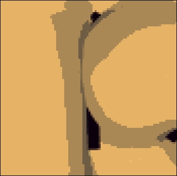
The edge polygon should extend vertically throughout the middle of the preceding figure, but is clipped because it falls behind the part of the mesh that is nearby. This issue can be solved by using custom depth testing when rendering the silhouette edges. Refer to the blog post mentioned earlier for details on this technique. It may also be possible to turn depth testing off when rendering the edges, being careful not to render any edges from the opposite side of the model.
- A whitepaper on using the geometry shader for fur and fins: http://developer.download.nvidia.com/whitepapers/2007/SDK10/FurShellsAndFins.pdf
- The Creating shadows using shadow volumes and the geometry shader recipe in Chapter 7, Shadows
- The Creating a cartoon shading effect recipe in Chapter 3, Lighting, Shading, and Optimization