
In the Implementing pseudo-isosurface rendering in single-pass GPU ray casting recipe, we implemented pseudo-isosurface rendering in single-pass GPU ray casting. However, these isosurfaces are not composed of triangles; so it is not possible for us to uniquely address individual isosurface regions easily to mark different areas in the volume dataset. This can be achieved by doing an isosurface extraction process for a specific isovalue by traversing the entire volume dataset. This method is known as the Marching Tetrahedra (MT) algorithm. This algorithm traverses the whole volume dataset and tries to fit a specific polygon based on the intersection criterion. This process is repeated for the whole volume and finally, we obtain the polygonal mesh from the volume dataset.
The code for this recipe is in the Chapter7/MarchingTetrahedra directory. For convenience, we will wrap the Marching Tetrahedra algorithm in a simple class called TetrahedraMarcher.
Let us start this recipe by following these simple steps:
- Load the 3D volume data and store it into an array:
std::ifstream infile(filename.c_str(), std::ios_base::binary); if(infile.good()) { pVolume = new GLubyte[XDIM*YDIM*ZDIM]; infile.read(reinterpret_cast<char*>(pVolume), XDIM*YDIM*ZDIM*sizeof(GLubyte)); infile.close(); return true; } else { return false; } - Depending on the sampling box size, run three loops to iterate through the entire volume voxel by voxel:
vertices.clear(); int dx = XDIM/X_SAMPLING_DIST; int dy = YDIM/Y_SAMPLING_DIST; int dz = ZDIM/Z_SAMPLING_DIST; glm::vec3 scale = glm::vec3(dx,dy,dz); for(int z=0;z<ZDIM;z+=dz) { for(int y=0;y<YDIM;y+=dy) { for(int x=0;x<XDIM;x+=dx) { SampleVoxel(x,y,z, scale); } } } - In each sampling step, estimate the volume density values at the eight corners of the sampling box:
GLubyte cubeCornerValues[8]; for( i = 0; i < 8; i++) { cubeCornerValues[i] = SampleVolume( x + (int)(a2fVertexOffset[i][0] *scale.x), y + (int)(a2fVertexOffset[i][1]*scale.y), z + (int)(a2fVertexOffset[i][2]*scale.z)); } - Estimate an edge flag value to identify the matching tetrahedra case based on the given isovalue:
int flagIndex = 0; for( i= 0; i<8; i++) { if(cubeCornerValues[i]<= isoValue) flagIndex |= 1<<i; } edgeFlags = aiCubeEdgeFlags[flagIndex]; - Use the lookup tables (
a2iEdgeConnection) to find the correct edges for the case and then use the offset table (a2fVertexOffset) to find the edge vertices and normals. These tables are defined in theTables.hheader in theChapter7/MarchingTetrahedra/directory.for(i = 0; i < 12; i++) { if(edgeFlags & (1<<i)) { float offset = GetOffset(cubeCornerValues[ a2iEdgeConnection[i][0] ], cubeCornerValues[ a2iEdgeConnection[i][1] ]); edgeVertices[i].x = x + (a2fVertexOffset[ a2iEdgeConnection[i][0] ][0] + offset * a2fEdgeDirection[i][0])*scale.x ; edgeVertices[i].y = y + (a2fVertexOffset[ a2iEdgeConnection[i][0] ][1] + offset * a2fEdgeDirection[i][1])*scale.y ; edgeVertices[i].z = z + (a2fVertexOffset[ a2iEdgeConnection[i][0] ][2] + offset * a2fEdgeDirection[i][2])*scale.z ; edgeNormals[i] = GetNormal( (int)edgeVertices[i].x , (int)edgeVertices[i].y , (int)edgeVertices[i].z ); } } - Finally, loop through the triangle connectivity table to connect the correct vertices and normals for the given case.
for(i = 0; i< 5; i++) { if(a2iTriangleConnectionTable[flagIndex][3*i] < 0) break; for(int j= 0; j< 3; j++) { int vertex = a2iTriangleConnectionTable[flagIndex][3*i+j]; Vertex v; v.normal = (edgeNormals[vertex]); v.pos = (edgeVertices[vertex])*invDim; vertices.push_back(v); } } - After the marcher is finished, we pass the generated vertices to a vertex array object containing a vertex buffer object:
glGenVertexArrays(1, &volumeMarcherVAO); glGenBuffers(1, &volumeMarcherVBO); glBindVertexArray(volumeMarcherVAO); glBindBuffer (GL_ARRAY_BUFFER, volumeMarcherVBO); glBufferData (GL_ARRAY_BUFFER, marcher-> GetTotalVertices()*sizeof(Vertex), marcher-> GetVertexPointer(), GL_STATIC_DRAW); glEnableVertexAttribArray(0); glVertexAttribPointer(0, 3, GL_FLOAT, GL_FALSE,sizeof(Vertex),0); glEnableVertexAttribArray(1); glVertexAttribPointer(1, 3, GL_FLOAT, GL_FALSE,sizeof(Vertex),(const GLvoid*)offsetof(Vertex, normal));
- For rendering of the generated geometry, we bind the Marching Tetrahedra VAO, bind our shader and then render the triangles. For this recipe, we output the per-vertex normals as color.
glBindVertexArray(volumeMarcherVAO); shader.Use(); glUniformMatrix4fv(shader("MVP"),1,GL_FALSE, glm::value_ptr(MVP*T)); glDrawArrays(GL_TRIANGLES, 0, marcher->GetTotalVertices()); shader.UnUse();
For convenience, we wrap the entire recipe in a reusable class called TetrahedraMarcher. Marching Tetrahedra, as the name suggests, marches a sampling box throughout the whole volume dataset. To give a bird's eye view there are several cases to consider based on the distribution of density values at the vertices of the sampling cube. Based on the sampling values at the eight corners and the given isovalue, a flag index is generated. This flag index gives us the edge flag by a lookup in a table. This edge flag is then used in an edge lookup table, which is predefined for all possible edge configurations of the marching tetrahedron. The edge connection table is then used to find the appropriate offset for the corner values of the sampling box. These offsets are then used to obtain the edge vertices and normals for the given tetrahedral case. Once the list of edge vertices and normals are estimated, the triangle connectivity is obtained based on the given flag index.
Now we will detail the steps in the Marching Tetrahedra algorithm. First, the flag index is obtained by iterating through all eight sampling cube vertices and comparing the density value at the vertex location with the given isovalue as shown in the following code. The flag index is then used to retrieve the edge flags from the looktup table (aiCubeEdgeFlags).
flagIndex = 0;
for( i= 0; i<8; i++) {
if(cubeCornerValues[i] <= isoValue)
flagIndex |= 1<<i;
}
edgeFlags = aiCubeEdgeFlags[flagIndex];The vertices and normals for the given index are stored in a local array by looking up the edge connection table (a2iEdgeConnection).
   for(i = 0; i < 12; i++)
  {
     if(edgeFlags & (1<<i))
      {
          float offset = GetOffset(cubeCornerValues[
          a2iEdgeConnection[i][0] ],
          cubeCornerValues[ a2iEdgeConnection[i][1] ]);
          edgeVertices[i].x = x + (a2fVertexOffset[
          a2iEdgeConnection[i][0] ][0] + offset *
          a2fEdgeDirection[i][0])*scale.x ;
          edgeVertices[i].y = y + (a2fVertexOffset[
          a2iEdgeConnection[i][0] ][1] + offset *
          a2fEdgeDirection[i][1])*scale.y ;
          edgeVertices[i].z = z + (a2fVertexOffset[
          a2iEdgeConnection[i][0] ][2] + offset *
          a2fEdgeDirection[i][2])*scale.z ;
          edgeNormals[i] = GetNormal( (int)edgeVertices[i].x ,
          (int)edgeVertices[i].y ,  (int)edgeVertices[i].z  );
      }
  }
Finally, the triangle connectivity table (a2iTriangleConnectionTable) is used to obtain the proper vertex and normal ordering and these attributes are then stored into a vectors.
for(i = 0; i< 5; i++) {
if(a2iTriangleConnectionTable[flagIndex][3*i] < 0)
break;
for(int j= 0; j< 3; j++) {
int vertex = a2iTriangleConnectionTable[flagIndex][3*i+j];
Vertex v;
v.normal = (edgeNormals[vertex]);
v.pos = (edgeVertices[vertex])*invDim;
vertices.push_back(v);
}
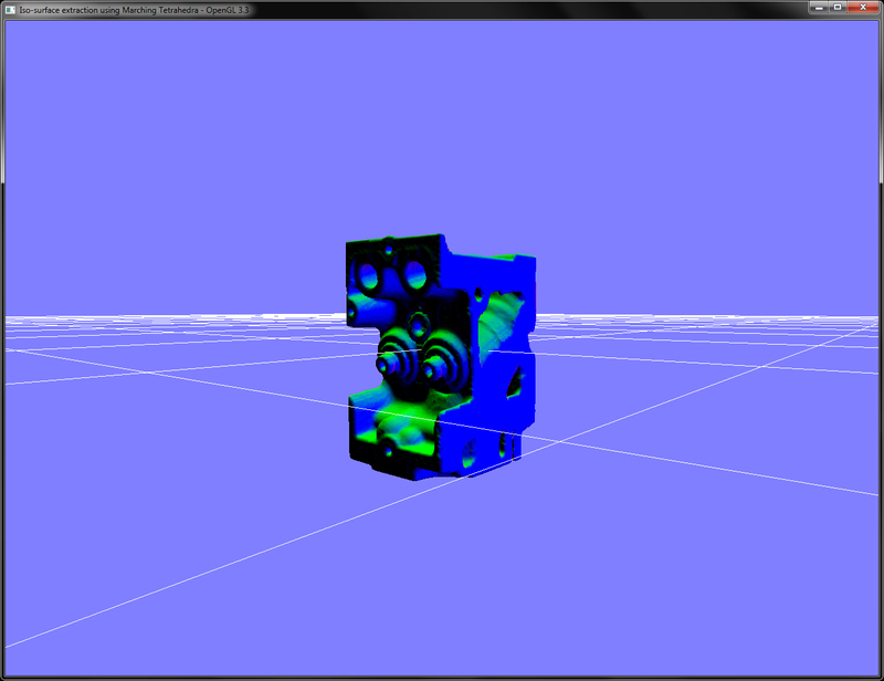
}After the Marching Tetrahedra code is processed, we store the generated vertices and normals in a buffer object. In the rendering code, we bind the appropriate vertex array object, bind our shader and then draw the triangles. The fragment shader for this recipe outputs the per-vertex normals as colors.
#version 330 core
layout(location = 0) out vec4 vFragColor;
smooth in vec3 outNormal;
void main() {
   vFragColor = vec4(outNormal,1);
}The demo application for this recipe renders the engine dataset as shown in the following screenshot. The fragment shader renders the isosurface normals as color.
Pressing the W key toggles the wireframe display, which shows the underlying isosurface polygons for isovalue of 40 as shown in the following screenshot:

While in this recipe, we focused on the Marching Tetrahedra algorithm. There is another, more robust method of triangulation called Marching Cubes, which gives a more robust polygonisation as compared to the Marching Tetrahedra algorithm.
- Polygonising a scalar field, Paul Bourke: http://paulbourke.net/geometry/polygonise/
- Volume Rendering: Marching Cubes Algorithm, http://cns-alumni.bu.edu/~lavanya/Graphics/cs580/p5/web-page/p5.html
- An implementation of Marching Cubes and Marching Tetrahedra Algorithms, http://www.siafoo.net/snippet/100