In the simplest terms, primitives are just basic shapes that are drawn in OpenGL. In this section, we will provide a brief overview of the main geometric primitives that are supported by OpenGL and focus specifically on three commonly used primitives (which will also appear in our demo applications): points, lines, and triangles.
We begin with a simple, yet very useful, building block for many visualization problems: a point primitive. A point can be in the form of ordered pairs in 2D, or it can be visualized in the 3D space.
To simplify the workflow and improve the readability of the code, we first define a structure called Vertex, which encapsulates the fundamental elements such as the position and color of a vertex.
typedef struct
{
  GLfloat x, y, z; //position
  GLfloat r, g, b, a; //color and alpha channels
} Vertex;
Now, we can treat every object and shape in terms of a set of vertices (with a specific color) in space. In this chapter, as our focus is on 2D visualization, the z positions of vertices are often manually set to 0.0f.
We can create a vertex at the center of the screen (0, 0, 0) with a white color as an example:
Vertex v = {0.0f, 0.0f, 0.0f, 1.0f, 1.0f, 1.0f, 1.0f};Note that the color element consists of the red, green, blue, and alpha channels. These values range from 0.0 to 1.0. The alpha channel allows us to create transparency (0: fully transparent; 1: fully opaque) so that objects can be blended together.
We can first define a function called drawPoint to encapsulate the complexity of OpenGL primitive functions, illustrated as follows:
- Create a function called
drawPointto draw points which takes in two parameters (the vertex and size of the point):void drawPoint(Vertex v1, GLfloat size){ - Specify the size of the point:
glPointSize(size);
- Set the beginning of the list of vertices to be specified and indicate the primitive type associated with the vertices (
GL_POINTSin this case):glBegin(GL_POINTS);
- Set the color and the vertex position using the fields from the
Vertexstructure:glColor4f(v1.r, v1.g, v1.b, v1.a); glVertex3f(v1.x, v1.y, v1.z);
- Set the end of the list:
glEnd(); }
- In addition, we can define a function called
drawPointsDemoto encapsulate the complexity further. This function draws a series of points with an increasing size:void drawPointsDemo(int width, int height){ GLfloat size=5.0f; for(GLfloat x = 0.0f; x<=1.0f; x+=0.2f, size+=5) { Vertex v1 = {x, 0.0f, 0.0f, 1.0f, 1.0f, 1.0f, 1.0f}; drawPoint(v1, size); } }
Finally, let's integrate these two functions into a complete OpenGL demo program (refer to identical steps in Chapter 1, Getting Started withOpenGL):
- Create a source file called
main_point.cpp, and then include the header file for the GLFW library and standard C++ libraries:#include <GLFW/glfw3.h> #include <stdlib.h> #include <stdio.h>
- Define the size of the window for display:
const int WINDOWS_WIDTH = 640*2; const int WINDOWS_HEIGHT = 480;
- Define the
Vertexstructure and function prototypes:typedef struct { GLfloat x, y, z; GLfloat r, g, b, a; } Vertex; void drawPoint(Vertex v1, GLfloat size); void drawPointsDemo(int width, int height); - Implement the
drawPointanddrawPointsDemofunctions, as shown previously. - Initialize GLFW and create a GLFW window object:
int main(void) { GLFWwindow* window; if (!glfwInit()) exit(EXIT_FAILURE); window = glfwCreateWindow(WINDOWS_WIDTH, WINDOWS_HEIGHT, "Chapter 2: Primitive drawings", NULL, NULL); if (!window){ glfwTerminate(); exit(EXIT_FAILURE); } glfwMakeContextCurrent(window); - Enable anti-aliasing and smoothing:
glEnable(GL_POINT_SMOOTH); glHint(GL_POINT_SMOOTH_HINT, GL_NICEST); glEnable(GL_BLEND); glBlendFunc(GL_SRC_ALPHA, GL_ONE_MINUS_SRC_ALPHA);
- Define a loop that terminates when the window is closed. Set up the viewport (using the size of the window) and clear the color buffer at the beginning of each iteration to update with new content:
while (!glfwWindowShouldClose(window)) { float ratio; int width, height; glfwGetFramebufferSize(window, &width, &height); ratio = (float) width / (float)height; glViewport(0, 0, width, height); glClear(GL_COLOR_BUFFER_BIT); - Set up the camera matrix for orthographic projection:
glMatrixMode(GL_PROJECTION); glLoadIdentity(); //Orthographic Projection glOrtho(-ratio, ratio, -1.f, 1.f, 1.f, -1.f); glMatrixMode(GL_MODELVIEW); glLoadIdentity(); glClear(GL_COLOR_BUFFER_BIT | GL_DEPTH_BUFFER_BIT); - Call the
drawPointsDemofunction:drawPointsDemo(width, height);
- Swap the front and back buffers of the window and process the event queue (such as keyboard inputs) to avoid lock-up:
glfwSwapBuffers(window); glfwPollEvents(); } - Release the memory and terminate the GLFW library. Then, exit the application:
glfwDestroyWindow(window); glfwTerminate(); exit(EXIT_SUCCESS); }
Here is the result (with anti-aliasing disabled) showing a series of points with an increasing size (that is, the diameter of each point as specified by glPointSize):
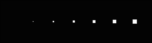
The glBegin and glEnd functions delimit the list of vertices corresponding to a desired primitive (GL_POINTS in this demo). The glBegin function accepts a set of symbolic constants that represent different drawing methods, including GL_POINTS, GL_LINES, and GL_TRIANGLES, as discussed in this chapter.
There are several ways to control the process of drawing points. First, we can set the diameter of each point (in pixels) with the glPointSize function. By default, a point has a diameter of 1 without anti-aliasing (a method to smooth sampling artifacts) enabled. Also, we can define the color of each point as well as the alpha channel (transparency) using the glColor4f function. The alpha channel allows us to overlay points and blend graphics elements. This is a powerful, yet very simple, technique used in graphics design and user interface design. Lastly, we define the position of the point in space with the glVertex3f function.
In OpenGL, we can define the projection transformation in two different ways: orthographic projection or perspective projection. In 2D drawing, we often use orthographic projection which involves no perspective correction (for example, the object on screen will remain the same size regardless of its distance from the camera). In 3D drawing, we use perspective projection to create more realistic-looking scenes similar to how the human eye sees. In the code, we set up an orthographic projection with the glOrtho function. The glOrtho function takes these parameters: the coordinates of the vertical clipping plane, the coordinates of the horizontal clipping plane, and the distance of the nearer and farther depth clipping planes. These parameters determine the projection matrix, and the detailed documentation can be found in https://developer.apple.com/library/mac/documentation/Darwin/Reference/ManPages/man3/glOrtho.3.html.
Anti-aliasing and smoothing are necessary to produce the polished look seen in modern graphics. Most graphics cards support native smoothing and in OpenGL, it can be enabled as follows:
glEnable(GL_POINT_SMOOTH); glEnable(GL_BLEND); glBlendFunc(GL_SRC_ALPHA, GL_ONE_MINUS_SRC_ALPHA);
Here is the final result with anti-aliasing enabled, showing a series of circular points with an increasing size:
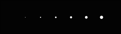
Note that in the preceding diagram, the points are now rendered as circles instead of squares with the anti-aliasing feature enabled. Readers are encouraged to disable and enable the features of the preceding diagram to see the effects of the operation.
In this tutorial, we have focused on the C programming style due to its simplicity. In the upcoming chapters, we will migrate to an object-oriented programming style using C++. In addition, in this chapter, we focus on three basic primitives (and discuss the derivatives of these primitives where appropriate): GL_POINTS, GL_LINES, and GL_TRIANGLES. Here is a more extensive list of primitives supported by OpenGL (refer to https://www.opengl.org/wiki/Primitive for more information):
GL_POINTS, GL_LINES, GL_LINE_STRIP, GL_LINE_LOOP, GL_TRIANGLES, GL_TRIANGLE_STRIP, GL_TRIANGLE_FAN, GL_QUADS, GL_QUAD_STRIP, and GL_POLYGON
One natural extension now is to connect a line between data points and then to connect the lines together to form a grid for plotting. In fact, OpenGL natively supports drawing line segments, and the process is very similar to that of drawing a point.
In OpenGL, we can simply define a line segment with a set of 2 vertices, and a line will be automatically formed between them by choosing GL_LINES as the symbolic constant in the glBegin statement.
Here, we define a new line drawing function called drawLineSegment which users can test by simply replacing the drawPointsDemo function in the previous section:
- Define the
drawLineSegmentfunction which takes in two vertices and the width of the line as inputs:void drawLineSegment(Vertex v1, Vertex v2, GLfloat width) { - Set the width of the line:
glLineWidth(width);
- Set the primitive type for line drawing:
glBegin(GL_LINES);
- Set the vertices and the color of the line:
glColor4f(v1.r, v1.g, v1.b, v1.a); glVertex3f(v1.x, v1.y, v1.z); glColor4f(v2.r, v2.g, v2.b, v2.a); glVertex3f(v2.x, v2.y, v2.z); glEnd(); }
In addition, we define a new grid drawing function called drawGrid, built on top of the drawLineSegment function as follows:
void drawGrid(GLfloat width, GLfloat height, GLfloat grid_width){
  //horizontal lines
  for(float i=-height; i<height; i+=grid_width){
    Vertex v1 = {-width, i, 0.0f, 1.0f, 1.0f, 1.0f, 1.0f};
    Vertex v2 = {width, i, 0.0f, 1.0f, 1.0f, 1.0f, 1.0f};
    drawLineSegment(v1, v2);
  }
  //vertical lines
  for(float i=-width; i<width; i+=grid_width){
    Vertex v1 = {i, -height, 0.0f, 1.0f, 1.0f, 1.0f, 1.0f};
    Vertex v2 = {i, height, 0.0f, 1.0f, 1.0f, 1.0f, 1.0f};
    drawLineSegment(v1, v2);
  }
}
Finally, we can execute the full demo by replacing the call for the drawPointsDemo function in the previous section with the following drawLineDemo function:
void drawLineDemo(){
//draw a simple grid
drawGrid(5.0f, 1.0f, 0.1f);
//define the vertices and colors of the line segments
Vertex v1 = {-5.0f, 0.0f, 0.0f, 1.0f, 0.0f, 0.0f, 0.7f};
Vertex v2 = {5.0f, 0.0f, 0.0f, 0.0f, 1.0f, 0.0f, 0.7f};
Vertex v3 = {0.0f, 1.0f, 0.0f, 0.0f, 0.0f, 1.0f, 0.7f};
Vertex v4 = {0.0f, -1.0f, 0.0f, 0.0f, 0.0f, 1.0f, 0.7f};
//draw the line segments
drawLineSegment(v1, v2, 10.0f);
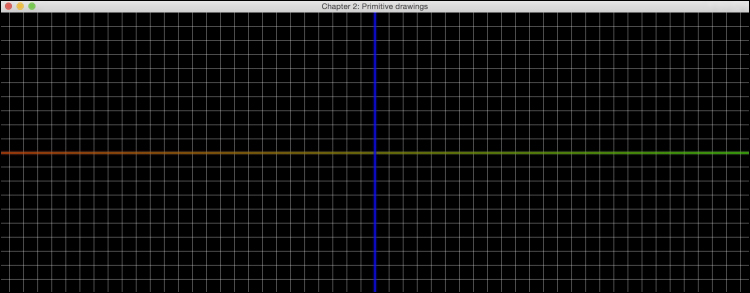
drawLineSegment(v3, v4, 10.0f);
}Here is a screenshot of the demo showing a grid with equal spacing and the x and y axes drawn with the line primitives:
There are multiple ways of drawing line segments in OpenGL. We have demonstrated the use of GL_LINES which takes every consecutive pair of vertices in the list to form an independent line segment for each pair. On the other hand, if you would like to draw a line without gaps, you can use the GL_LINE_STRIP option, which connects all the vertices in a consecutive fashion. Finally, to form a closed loop sequence in which the endpoints of the lines are connected, you would use the GL_LINE_LOOP option.
In addition, we can modify the width and the color of a line with the glLineWidth and glColor4f functions for each vertex, respectively.
We will now move on to another very commonly used primitive, namely a triangle, which forms the basis for drawing all possible polygons.
Similar to drawing a line segment, we can simply define a triangle with a set of 3 vertices, and line segments will be automatically formed by choosing GL_TRIANGLES as the symbolic constant in the glBegin statement.
Finally, we define a new function called drawTriangle, which users can test by simply replacing the drawPointsDemo function. We will also reuse the drawGrid function from the previous section:
- Define the
drawTrianglefunction, which takes in three vertices as the input:void drawTriangle(Vertex v1, Vertex v2, Vertex v3){ - Set the primitive type to draw triangles:
glBegin(GL_TRIANGLES);
- Set the vertices and the color of the triangle:
  glColor4f(v1.r, v1.g, v1.b, v1.a);
  glVertex3f(v1.x, v1.y, v1.z);
  glColor4f(v2.r, v2.g, v2.b, v2.a);
  glVertex3f(v2.x, v2.y, v2.z);
  glColor4f(v3.r, v3.g, v3.b, v3.a);
  glVertex3f(v3.x, v3.y, v3.z);
  glEnd(),
}
- Execute the demo by replacing the call for the
drawPointsDemofunction in the full demo code with the followingdrawTriangleDemofunction:void drawTriangleDemo(){ //Triangle Demo Vertex v1 = {0.0f, 0.8f, 0.0f, 1.0f, 0.0f, 0.0f, 0.6f}; Vertex v2 = {-1.0f, -0.8f, 0.0f, 0.0f, 1.0f, 0.0f, 0.6f}; Vertex v3 = {1.0f, -0.8f, 0.0f, 0.0f, 0.0f, 1.0f, 0.6f}; drawTriangle(v1, v2, v3); }
Here is the final result with a triangle rendered with 60 percent transparency overlaid on top of the grid lines:

While the process of drawing a triangle in OpenGL appears similar to previous examples, there are some subtle differences and further complexities that can be incorporated. There are three different modes in this primitive (GL_TRIANGLES, GL_TRIANGLE_STRIP, and GL_TRIANGLE_FAN), and each handles the vertices in a different manner. First, GL_TRIANGLES takes three vertices from a given list to create a triangle. The triangles are independently formed from each triplet of the vertices (that is, every three vertices are turned into a different triangle). On the other hand, GL_TRIANGLE_STRIP forms a triangle with the first three vertices, and each subsequent vertex forms a new triangle using the previous two vertices. Lastly, GL_TRIANGLE_FAN creates an arbitrarily complex convex polygon by creating triangles that have a common vertex in the center specified by the first vertex v_1, which forms a fan-shaped structure consisting of triangles. In other words, triangles will be generated in the grouping order specified as follows:
(v1, v2, v3), (v1, v3, v4),...,(v1, vn-1, vn)
for n vertices
Although a different color is set for each vertex, OpenGL handles color transition (linear interpolation) automatically, as shown in the triangle drawing in the previous example. The vertices are set to red, green, and blue, but the spectrum of colors can be clearly seen. Additionally, transparency can be set using the alpha channel, which enables us to clearly see the grid behind the triangle. With OpenGL, we can also add other elements, such as the advanced handling of color and shading, which will be discussed in the upcoming chapters.