
A straightforward way to leverage shaders for animation is to simply transform the vertices within the vertex shader based on some time-dependent function. The OpenGL application supplies static geometry, and the vertex shader modifies the geometry using the current time (supplied as a uniform variable). This moves the computation of the vertex position from the CPU to the GPU, and leverages whatever parallelism the graphics driver makes available.
In this example, we'll create a waving surface by transforming the vertices of a tessellated quad based on a sine wave. We'll send down the pipeline a set of triangles that make up a flat surface in the x-z plane. In the vertex shader we'll transform the y-coordinate of each vertex based on a time-dependent sine function, and compute the normal vector of the transformed vertex. The following image shows the desired result. (You'll have to imagine that the waves are travelling across the surface from left to right).

Note
Alternatively, we could use a noise texture to animate the vertices (that make up the surface) based on a random function. (See Chapter 8, Using Noise in Shaders, for details on noise textures).
Before we jump into the code, let's take a look at the mathematics that we'll need.
We'll transform the y-coordinate of the surface as a function of the current time and the modeling x-coordinate. To do so, we'll use the basic plane wave equation as shown in the following diagram:

Where A is the wave's amplitude (the height of the peaks), lambda (λ) is the wavelength (the distance between successive peaks), and v is the wave's velocity. The previous image shows an example of the wave when t = 0 and the wavelength is equal to one. We'll configure these coefficients through uniform variables.
In order to render the surface with proper shading, we also need the normal vector at the transformed location. We can compute the normal vector using the (partial) derivative of the previous function. The result is the following equation:
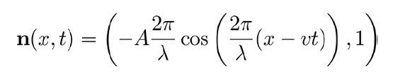
Of course, the previous vector should be normalized before using it in our shading model.
Set up your OpenGL application to render a flat, tessellated surface in the x-z plane. The results will look better if you use a large number of triangles. Also, keep track of the animation time using whatever method you prefer. Provide the current time to the vertex shader via the uniform variable Time.
The other important uniform variables are the coefficients of the previous wave equation.
K: It is the wavenumber (2π/λ).Velocity: It is the wave's velocity.Amp: It is the wave's amplitude.
Set up your program to provide appropriate uniform variables for your chosen shading model.
Use the following steps:
- Use the following code for the vertex shader:
layout (location = 0) in vec3 VertexPosition; out vec4 Position; out vec3 Normal; uniform float Time; // The animation time // Wave parameters uniform float K; // Wavenumber uniform float Velocity; // Wave's velocity uniform float Amp; // Wave's amplitude uniform mat4 ModelViewMatrix; uniform mat3 NormalMatrix; uniform mat4 MVP; void main() { vec4 pos = vec4(VertexPosition,1.0); // Translate the y coordinate float u = K * (pos.x - Velocity * Time); pos.y = Amp * sin( u ); // Compute the normal vector vec3 n = vec3(0.0); n.xy = normalize(vec2(-K * Amp *cos( u ), 1.0)); // Send position and normal (in camera cords) to frag. Position = ModelViewMatrix * pos; Normal = NormalMatrix * n; // The position in clip coordinates gl_Position = MVP * pos; } - Create a fragment shader that computes the fragment color based on the variables
PositionandNormalusing whatever shading model you choose (see the Using per-fragment shading for improved realism recipe in Chapter 3, Lighting, Shading, and Optimizations).
The vertex shader takes the position of the vertex and updates the y-coordinate using the wave equation discussed previously. After the first three statements, the variable pos is just a copy of the input variable VertexPosition with the modified y-coordinate.
We then compute the normal vector using the previous equation, normalize the result and store it in the variable n. Since the wave is really just a two-dimensional wave (doesn't depend on z), the z component of the normal vector will be zero.
Finally we pass along the new position and normal to the fragment shader after converting to camera coordinates. As usual, we also pass the position in clip coordinates to the built-in variable gl_Position.
Modifying the vertex position within the vertex shader is a straightforward way to offload some computation from the CPU to the GPU. It also eliminates the possible need to transfer vertex buffers between the GPU memory and main memory in order to modify the positions.
The main disadvantage is that the updated positions are not available on the CPU side. For example, they might be needed for additional processing (such as collision detection). However, there are a number of ways to provide this data back to the CPU. One technique might be clever use of FBOs to receive the updated positions from the fragment shader. In a following recipe, we'll look at another technique that makes use of a newer OpenGL feature called transform feedback.
- The Using per-fragment shading for improved realism recipe in Chapter 3, Lighting, Shading, and Optimization