
Transparency can be a difficult effect to do accurately in pipeline architectures like OpenGL. The general technique is to draw opaque objects first, with the depth buffer enabled, then to make the depth buffer read-only (using glDepthMask), disable the depth test, and draw the transparent geometry. However, care must be taken to ensure that the transparent geometry is drawn from "back to front". That is, objects farther from the viewer should be drawn before the objects that are closer. This requires some sort of depth-sorting to take place prior to rendering.
The following images show an example of a block of small, semi-transparent spheres with some semi-transparent cubes placed evenly within them. On the right-hand side, the objects are rendered in an arbitrary order, using standard OpenGL blending. The result looks incorrect because objects are blended in an improper order. The cubes, which were drawn last, appear to be on top of the spheres, and the spheres look "jumbled", especially in the middle of the block. On the left, the scene is drawn using proper ordering, so objects appear to be oriented correctly with respect to depth, and the overall look is more realistic looking.

Order Independent Transparency (OIT) means that we can draw objects in any order, and still get accurate results. Depth sorting is done at some other level, perhaps within the fragment shader, so that the programmer need not sort objects before rendering. There are a variety of techniques for doing this; one of the most common technique is to keep a list of colors for each pixel, sort them by depth, and then blend them together in the fragment shader. In this recipe we'll use this technique to implement OIT making use of some of the newest features in OpenGL 4.3.
Shader storage buffer objects (SSBO) and image load/store are some of the newest features in OpenGL, introduced in 4.3 and 4.2, respectively. They allow arbitrary read/write access to data from within a shader. Prior to this, shaders were very limited in terms of what data they could access. They could read from a variety of locations (textures, uniforms, and so on), but writing was very limited. Shaders could only write to controlled, isolated locations such as fragment shader outputs and transform feedback buffers. This was for very good reason. Since shaders can execute in parallel and in a seemingly arbitrary order, it is very difficult to ensure that data is consistent between instantiations of a shader. Data written by one shader instance might not be visible to another shader instance whether or not that instance is executed after the other. Despite this, there are good reasons for wanting to read and write to shared locations. With the advent of SSBOs and image load/store, that capability is now available to us. We can create buffers and textures (called images) with read/write access to any shader instance. This is especially important for compute shaders, the subject of Chapter 10, Using Compute Shaders. However, this power comes at a price. The programmer must now be very careful to avoid the types of memory consistency errors that come along with writing to memory that is shared among parallel threads. Additionally, the programmer must be aware of the performance issues that come with synchronization between shader invocations.
In this recipe, we'll use SSBOs and image load/store to implement order-independent transparency. We'll use two passes. In the first pass, we'll render the scene geometry and store a linked list of fragments for each pixel. After the first pass, each pixel will have a corresponding linked list containing all fragments that were written to that pixel including their depth and color. In the second pass, we'll draw a full-screen quad to invoke the fragment shader for each pixel. In the fragment shader, we'll extract the linked list for the pixel, sort the fragments by depth (largest to smallest), and blend the colors in that order. The final color will then be sent to the output device.
That's the basic idea, so let's dig into the details. We'll need three memory objects that are shared among the fragment shader instances.
- An atomic counter: This is just an unsigned integer that we'll use to keep track of the size of our linked list buffer. Think of this as the index of the first unused slot in the buffer.
- A head-pointer texture that corresponds to the size of the screen: The texture will store a single unsigned integer in each texel. The value is the index of the head of the linked list for the corresponding pixel.
- A buffer containing all of our linked lists: Each item in the buffer will correspond to a fragment, and contains a struct with the color and depth of the fragment as well as an integer, which is the index of the next fragment in the linked list.
In order to understand how all of this works together, let's consider a simple example. Suppose that our screen is 3 pixels wide and 3 pixels high. We'll have a head pointer texture that is the same dimensions, and we'll initialize all of the texels to a special value that indicates the end of the linked list (an empty list). In the following diagram, that value is shown as an 'x', but in practice, we'll use 0xffffffff. The initial value of the counter is zero, and the linked list buffer is allocated to a certain size, but treated as empty initially. The initial state of our memory looks like the following diagram:

Now suppose that a fragment is rendered at the position (0,1) with a depth of 0.75. The fragment shader will take the following steps:
- Increment the atomic counter. The new value will be 1, but we'll use the previous value (0) as the index for our new node in the linked list.
- Update the head pointer texture at (0,1) with the previous value of the counter (0). This is the index of the new head of the linked list at that pixel. Hold on to the previous value that was stored there (x), we'll need that in the next step.
- Add a new value into the linked list buffer at the location corresponding to the previous value of the counter (0). Store here the color of the fragment and its depth. Store in the "next" component the previous value of the head pointer texture at (0,1) that we held on to in step 2. In this case, it is the special value indicating the end of the list.
After processing this fragment, the memory layout looks like the following:

Now, suppose another fragment is rendered at (0,1), with a depth of 0.5. The fragment shader will execute the same steps as the previous ones, resulting in the following memory layout:

We now have a 2-element linked list starting at index 1 and ending at index 0. Suppose, now that we have three more fragments in the following order: a fragment at (1,1) with a depth of 0.2, a fragment at (0,1) with a depth of 0.3, and a fragment at (1,1) with a depth of 0.4. Following the same steps for each fragment, we get the following result:
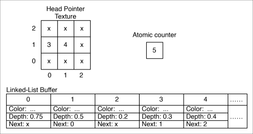
The linked list at (0,1) consists of fragments{3, 1, 0} and the linked list at (1,1) contains fragments {4, 2}.
Now, we must keep in mind that due to the highly parallel nature of GPUs, fragments can be rendered in virtually any order. For example, fragments from two different polygons might proceed through the pipeline in the opposite order as to when the draw instructions for polygons were issued. As a programmer, we must not expect any specific ordering of fragments. Indeed, instructions from separate instances of the fragment shader may interleave in arbitrary ways. The only thing that we can be sure of is that the statements within a particular instance of the shader will execute in order. Therefore, we need to convince ourselves that any interleaving of the previous three steps will still result in a consistent state. For example, suppose instance one executes steps 1 and 2, then another instance (another fragment, perhaps at the same fragment coordinates) executes steps 1, 2, and 3, before the first instance executes step 3. Will the result still be consistent? I think you can convince yourself that it will be, even though the linked list will be broken for a short time during the process. Try working through other interleavings and convince yourself that we're OK.
Note
Not only can statements within separate instances of a shader interleave with each other, but the subinstructions that make up the statements can interleave. (For example, the subinstructions for an increment operation consist of a load, increment, and a store.) What's more, they could actually execute at exactly the same time. Consequently, if we aren't careful, nasty memory consistency issues can crop up. To help avoid this, we need to make careful use of the GLSL support for atomic operations.
Recent versions of OpenGL (4.2 and 4.3) have introduced the tools that we need to make this algorithm possible. OpenGL 4.2 introduced atomic counters and the ability to read and write to arbitrary locations within a texture (called image load/store). OpenGL 4.3 introduced shader storage buffer objects. We'll make use of all three of these features in this example, as well as the various atomic operations and memory barriers that go along with them.
There's a bunch of setup needed here, so I'll go into a bit of detail with some code segments. First, we'll set up a buffer for our atomic counter:
GLuint counterBuffer;
glGenBuffers(1, &counterBuffer);
glBindBufferBase(GL_ATOMIC_COUNTER_BUFFER, 0, counterBuffer);
glBufferData(GL_ATOMIC_COUNTER_BUFFER, sizeof(GLuint), NULL,
             GL_DYNAMIC_DRAW);
Next, we create a buffer for our linked list storage:
GLuint llBuf;
glGenBuffers(1, &llBuf);
glBindBufferBase(GL_SHADER_STORAGE_BUFFER, 0, llBuf);
glBufferData(GL_SHADER_STORAGE_BUFFER, maxNodes * nodeSize, NULL,
             GL_DYNAMIC_DRAW);
Note
nodeSize in the previous code is the size of a struct NodeType used in the fragment shader (in the later part of code). This is computed based on the std430 layout. For details on the std430 layout, see the OpenGL specification document. For this example, nodeSize is 5 * sizeof(GLfloat) + sizeof(GLuint).
We also need to create a texture to hold the list head pointers. We'll use 32-bit unsigned integers, and bind it to image unit 0:
glGenTextures(1, &headPtrTex);
glBindTexture(GL_TEXTURE_2D, headPtrTex);
glTexStorage2D(GL_TEXTURE_2D, 1, GL_R32UI, width, height);
glBindImageTexture(0, headPtrTex, 0, GL_FALSE, 0, GL_READ_WRITE,
                   GL_R32UI);
After we render each frame, we need to clear the texture by setting all texels to a value of 0xffffffff. To help with that, we'll create a buffer of the same size as the texture, with each value set to our "clear value":
vector<GLuint> headPtrClear(width * height, 0xffffffff);
GLuint clearBuf;
glGenBuffers(1, &clearBuf);
glBindBuffer(GL_PIXEL_UNPACK_BUFFER, clearBuf);
glBufferData(GL_PIXEL_UNPACK_BUFFER,
             headPtrClear.size()*sizeof(GLuint),
             &headPtrClear[0], GL_STATIC_COPY);
That's all the buffers we'll need. Note the fact that we've bound the head pointer texture to image unit 0, the atomic counter buffer to index 0 of the GL_ATOMIC_COUNTER_BUFFER binding point (glBindBufferBase), and the linked list storage buffer to index 0 of the GL_SHADER_STORAGE_BUFFER binding point. We'll refer back to that later.
Use a pass-through vertex shader that sends the position and normal along in eye coordinates.
With all of the buffers set up, we need two render passes. Before the first pass, we want to clear our buffers to default values (that is, empty lists), and to reset our atomic counter buffer to zero.
glBindBuffer(GL_PIXEL_UNPACK_BUFFER, clearBuf);
glBindTexture(GL_TEXTURE_2D, headPtrTex);
glTexSubImage2D(GL_TEXTURE_2D, 0, 0, 0, width, height,
                GL_RED_INTEGER, GL_UNSIGNED_INT, NULL);
GLuint zero = 0;
glBindBufferBase(GL_ATOMIC_COUNTER_BUFFER, 0, counterBuffer);
glBufferSubData(GL_ATOMIC_COUNTER_BUFFER, sizeof(GLuint), &zero);
In the first pass, we'll render the full scene geometry. Generally, we should render all the opaque geometry first, and store the results in a texture. However, we'll skip that step for this example to keep things simple and focused. Instead, we'll render only transparent geometry. When rendering the transparent geometry, we need to make sure to put the depth buffer in read-only mode (use glDepthMask). In the fragment shader, we add each fragment to the appropriate linked list.
layout (early_fragment_tests) in;

#define MAX_FRAGMENTS 75

in vec3 Position;
in vec3 Normal;

struct NodeType {
  vec4 color;
  float depth;
  uint next;
};

layout(binding=0, r32ui) uniform uimage2D headPointers;
layout(binding=0, offset=0) uniform atomic_uint
                                         nextNodeCounter;
layout(binding=0, std430) buffer linkedLists {
  NodeType nodes[];
};
uniform uint MaxNodes;

subroutine void RenderPassType();
subroutine uniform RenderPassType RenderPass;

…

subroutine(RenderPassType)
void pass1()
{
  // Get the index of the next empty slot in the buffer
  uint nodeIdx = atomicCounterIncrement(nextNodeCounter);

  // Is there space left in the buffer?
  if( nodeIdx < MaxNodes ) {
    // Update the head pointer image
    uint prevHead = imageAtomicExchange(headPointers,
                           ivec2(gl_FragCoord.xy), nodeIdx);

    // Set the color and depth of this new node to the color
    // and depth of the fragment.  The next pointer points to the
    // previous head of the list.
    nodes[nodeIdx].color = vec4(shadeFragment(), Kd.a);
    nodes[nodeIdx].depth = gl_FragCoord.z;
    nodes[nodeIdx].next = prevHead;
  }
}
Before rendering the second pass, we need to be sure that all of the data has been written to our buffers. In order to ensure that is indeed the case, we can use a memory barrier.
glMemoryBarrier( GL_ALL_BARRIER_BITS );
In the second pass, we don't render the scene geometry, just a single, screen-filling quad in order to invoke the fragment shader for each screen pixel. In the fragment shader, we start by copying the linked list for the fragment into a temporary array.
struct NodeType frags[MAX_FRAGMENTS];
int count = 0;

// Get the index of the head of the list
uint n = imageLoad(headPointers, ivec2(gl_FragCoord.xy)).r;

// Copy the linked list for this fragment into an array
while( n != 0xffffffff && count < MAX_FRAGMENTS) {
  frags[count] = nodes[n];
  n = frags[count].next;
  count++;
}
Then, we sort the fragments using insertion sort:
// Sort the array by depth (largest to smallest).
for( uint i = 1; i < count; i++ )
{
  struct NodeType toInsert = frags[i];
  uint j = i;
  while( j > 0 && toInsert.depth > frags[j-1].depth ) {
    frags[j] = frags[j-1];
    j--;
  }
  frags[j] = toInsert;
}
Finally, we blend the fragments "manually", and send the result to the output variable:
// Traverse the array, and blend the colors.
vec4 color = vec4(0.5, 0.5, 0.5, 1.0);  // Background color
for( int i = 0; i < count; i++ ) {
  color = mix( color, frags[i].color, frags[i].color.a);
}

// Output the final color
FragColor = color;To clear our buffers, prior to the first pass, we bind clearBuf to the GL_PIXEL_UNPACK_BUFFER binding point, and call glTexSubImage2D to copy data from clearBuf to the the head pointer texture. Note that when a non-zero buffer is bound to GL_PIXEL_UNPACK_BUFFER, glTexSubImage2D treats the last parameter as an offset into the buffer that is bound there. Therefore, this will initiate a copy from clearBuf into headPtrTex. Clearing the atomic counter is straightforward, but the use of glBindBufferBase may be a bit confusing. If there can be several buffers bound to the binding point (at different indices), then how does glBufferSubData know which buffer to target? It turns out that when we bind a buffer using glBindBufferBase, it is also bound to the "generic" binding point as well.
In the fragment shader during the first pass, we start with the layout specification enabling the early fragment test optimization.
layout (early_fragment_tests) in;
This is important because if any fragments are obscured by the opaque geometry, we don't want to add them to a linked list. If the early fragment test optimization is not enabled, the fragment shader may be executed for fragments that will fail the depth test, and hence will get added to the linked list. The previous statement ensures that the fragment shader will not execute for those fragments.
The definition of struct NodeType specifies the type of data that is stored in our linked list buffer. We need to store color, depth, and a pointer to the next node in the linked list.
The next three statements declare the objects related to our linked list storage. The first, headPointers, is the image object that stores the locations of the heads of each linked list. The layout qualifier indicates that it is located at image unit 0 (refer to the Getting ready section of this recipe), and the data type is r32ui (red, 32-bit, unsigned integer). The second object is our atomic counter nextNodeCounter. The layout qualifier indicates the index within the GL_ATOMIC_COUTER_BUFFER binding point (refer to the Getting ready section of this recipe), and the offset within the buffer at that location. Since we only have a single value in the buffer, the offset is 0, but in general, you might have several atomic counters located within a single buffer. Third is our linked-list storage buffer linkedLists. This is a shader storage buffer object. The organization of the data within the object is defined within the curly braces here. In this case, we just have an array of NodeType structures. The bounds of the array can be left undefined, the size being limited by the underlying buffer object that we created. The layout qualifiers define the binding and memory layout. The first, binding, indicates that the buffer is located at index 0 within the GL_SHADER_STORAGE_BUFFER binding point. The second, std430, indicates how memory is organized within the buffer. This is mainly important when we want to read the data back from the OpenGL side. As mentioned previously, this is documented in the OpenGL specification document.
The first step in the fragment shader during the first pass is to increment our atomic counter using atomicCounterIncrement. This will increment the counter in such a way that there is no possibility of memory consistency issues if another shader instance is attempting to increment the counter at the same time.
The return value of atomicCounterIncrement is the previous value of the counter. It is the next unused location in our linked list buffer. We'll use this value as the location where we'll store this fragment, so we store it in a variable named nodeIdx. It will also become the new head of the linked list, so the next step is to update the value in the headPointers image at this pixel's location gl_FragCoord.xy. We do so using another atomic operation: imageAtomicExchange. This replaces the value within the image at the location specified by the second parameter with the value of the third parameter. The return value is the previous value of the image at that location. This is the previous head of our linked list. We hold on to this value in prevHead, because we want to link our new head to that node, thereby restoring the consistency of the linked list with our new node at the head.
Finally, we update the node at nodeIdx with the color and depth of the fragment, and set the next value to the previous head of the list (prevHead). This completes the insertion of this fragment into the linked list at the head of the list.
After the first pass is complete, we need to make sure that all changes are written to our shader storage buffer and image object before proceeding. The only way to guarantee this is to use a memory barrier. The call to glMemoryBarrier will take care of this for us. The parameter to glMemoryBarrier is the type of barrier. We can "fine tune" the type of barrier to specifically target the kind of data that we want to read. However, just to be safe, and for simplicity, we'll use GL_ALL_BARRIER_BITS, which ensures that all possible data has been written.
In the second pass, we start by copying the linked list for the fragment into a temporary array. We start by getting the location of the head of the list from the headPointers image using imageLoad. Then we traverse the linked list with the while loop, copying the data into the array frags.
Next, we sort the array by depth from largest to smallest, using the insertion sort algorithm. Insertion sort works well on small arrays, so should be a fairly efficient choice here.
Finally, we combine all the fragments in order, using the mix function to blend them together based on the value of the alpha channel. The final result is stored in the output variable FragColor.
As mentioned previously, we've skipped anything that deals with opaque geometry. In general, one would probably want to render any opaque geometry first, with the depth buffer enabled, and store the rendered fragments in a texture. Then, when rendering the transparent geometry, one would disable writing to the depth buffer, and build the linked list as shown previously. Finally, you could use the value of the opaque texture as the background color when blending the linked lists.
This is the first example in this book that makes use of reading and writing from/to arbitrary (shared) storage from a shader. This capability, only recently introduced, has given us much more flexibility, but that comes at a price. As indicated previously, we have to be very careful to avoid memory consistency and coherence issues. The tools to do so include atomic operations and memory barriers, and this example has just scratched the surface. There's much more to come in Chapter 10, Using Compute Shaders when we look at compute shaders, and I recommend you read through the memory chapter in the OpenGL Programming Guide for much more detail than I can provide here.
- Chapter 10, Using Compute Shaders
- OpenGL Development Cookbook by Muhammad Mobeen Movania has several recipes in Chapter 6, GPU-based Alpha Blending and Global Illumination.