
As we discovered in the previous recipes, one of the main problems with shadow maps is aliasing. The problem essentially boils down to the fact that we are sampling the shadow map(s) at a different frequency (resolution) than we are using when rendering the scene. To minimize the aliasing we can blur the shadow edges (as in the previous recipes), or try to sample the shadow map at a frequency that is closer to the corresponding resolution in projected screen space. There are many techniques that help with the latter; for more details, I recommend the book Real-Time Shadows.
An alternate technique for shadow generation is called shadow volumes. The shadow volume method completely avoids the aliasing problem that plagues shadow maps. With shadow volumes, you get pixel-perfect hard shadows, without the aliasing artifacts of shadow maps. The following figure shows a scene with shadows that are produced using the shadow volume technique.

The shadow volume technique works by making use of the stencil buffer to mask out areas that are in shadow. We do this by drawing the boundaries of the actual shadow volumes (more on this below). A shadow volume is the region of space where the light source is occluded by an object. For example, the following figures show a representation of the shadow volumes of a triangle (left) and a sphere (right).
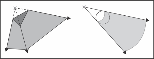
The boundaries of a shadow volume are made up of quads formed by extending the edges of the object away from the light source. For a single triangle, the boundaries would consist of three quads, extended from each edge, and triangular caps on each end. One cap is the triangle itself and the other is placed at some distance from the light source. For an object that consists of many triangles, such as the sphere above, the volume can be defined by the so-called silhouette edges. These are edges that are on or near the boundary between the shadow volume and the portion of the object that is lit. In general, a silhouette edge borders a triangle that faces the light and another triangle that faces away from the light. To draw the shadow volume, one would find all of the silhouette edges and draw extended quads for each edge. The caps of the volume could be determined by making a closed polygon (or triangle fan) that includes all the points on the silhouette edges, and similarly on the far end of the volume.
The shadow volume technique works in the following way. Imagine a ray that originates at the camera position and extends through a pixel on the near plane. Suppose that we follow that ray and keep track of a counter that is incremented every time that it enters a shadow volume and decremented each time that it exits a shadow volume. If we stop counting when we hit a surface, that point on the surface is occluded (in shadow) if our count is non-zero, otherwise, the surface is lit by the light source. The following figure shows an example of this idea:

The roughly horizontal line represents a surface that is receiving a shadow. The numbers represent the counter for each camera ray. For example, the rightmost ray with value +1 has that value because the ray entered two volumes and exited one along the way from the camera to the surface: 1 + 1 - 1 = 1. The rightmost ray has a value of zero at the surface because it entered and exited both shadow volumes: 1 + 1 - 1 - 1 = 0.
This all sounds fine in theory, but how can we trace rays in OpenGL? The good news is that we don't have to. The stencil buffer provides just what we need. With the stencil buffer, we can increment/decrement a counter for each pixel based on whether a front or back face is rendered into that pixel. So we can draw the boundaries of all of the shadow volumes, then for each pixel, increment the stencil buffer's counter when a front face is rendered to that pixel and decrement when it is a back face.
The key here is to realize that each pixel in the rendered figure represents an eye-ray (as in the above diagram). So for a given pixel, the value in the stencil buffer is the value that we would get if we actually traced a ray through that pixel. The depth test helps to stop tracing when we reach a surface.
In this recipe, we'll draw our shadow volumes with the help of the geometry shader. Rather than computing the shadow volumes on the CPU side, we'll render the geometry normally, and have the geometry shader produce the shadow volumes. In the Drawing silhouette lines using the geometry shader recipe in Chapter 6, Using Geometry and Tessellation Shaders, we saw how the geometry shader can be provided with adjacency information for each triangle. With adjacency information, we can determine whether a triangle has a silhouette edge. If the triangle faces the light, and a neighboring triangle faces away from the light, then the shared edge can be considered a silhouette edge, and used to create a polygon for the shadow volume.
The entire process is done in three passes. They are as follows:
- Render the scene normally, but write the shaded color to two separate buffers. We'll store the ambient component in one and the diffuse and specular components in another.
- Set up the stencil buffer so that the stencil test always passes, and front faces cause an increment and back faces cause a decrement. Make the depth buffer read-only, and render only the shadow-casting objects. In this pass, the geometry shader will produce the shadow volumes, and only the shadow volumes will be rendered to the fragment shader.
- Set up the stencil buffer so the test succeeds when the value is equal to zero. Draw a screen-filling quad, and combine the values of the two buffers from step one when the stencil test succeeds.
That's the high-level view, and there are many details. Let's go through them in the next sections.
We'll start by creating our buffers. We'll use a framebuffer object with a depth attachment and two color attachments. The ambient component can be stored in a renderbuffer (as opposed to a texture) because we'll blit (a fast copy) it over to the default framebuffer rather than reading from it as a texture. The diffuse + specular component will be stored in a texture. Create the ambient buffer (ambBuf), a depth buffer (depthBuf), and a texture (diffSpecTex), then set up the FBO.
glGenFramebuffers(1, &colorDepthFBO);
glBindFramebuffer(GL_FRAMEBUFFER, colorDepthFBO);
glFramebufferRenderbuffer(GL_FRAMEBUFFER, GL_DEPTH_ATTACHMENT,
                          GL_RENDERBUFFER, depthBuf);
glFramebufferRenderbuffer(GL_FRAMEBUFFER, GL_COLOR_ATTACHMENT0,
                          GL_RENDERBUFFER, ambBuf);
glFramebufferTexture2D(GL_FRAMEBUFFER, GL_COLOR_ATTACHMENT1,
                       GL_TEXTURE_2D, diffSpecTex, 0);
Set up the draw buffers so that we can write to the color attachments.
GLenum drawBuffers[] = {GL_COLOR_ATTACHMENT0,
                        GL_COLOR_ATTACHMENT1};
glDrawBuffers(2, drawBuffers);For the first pass, enable the framebuffer object that we set up above, and render the scene normally. In the fragment shader, send the ambient component and the diffuse + specular component to separate outputs.
layout( location = 0 ) out vec4 Ambient;
layout( location = 1 ) out vec4 DiffSpec;

void shade( )
{
  // Compute the shading model, and separate out the ambient
  // component.
  Ambient = …;   // Ambient
  DiffSpec = …;  // Diffuse + specular
}
void main() { shade(); }
In the second pass, we'll render our shadow volumes. We want to set up the stencil buffer so that the test always succeeds, and that front faces cause an increment, and back faces cause a decrement.
glClear(GL_STENCIL_BUFFER_BIT);
glEnable(GL_STENCIL_TEST);
glStencilFunc(GL_ALWAYS, 0, 0xffff);
glStencilOpSeparate(GL_FRONT, GL_KEEP, GL_KEEP, GL_INCR_WRAP);
glStencilOpSeparate(GL_BACK, GL_KEEP, GL_KEEP, GL_DECR_WRAP);
Also in this pass, we want to use the depth buffer from the first pass, but we want to use the default frame buffer, so we need to copy the depth buffer over from the FBO used in the first pass. We'll also copy over the color data, which should contain the ambient component.
glBindFramebuffer(GL_READ_FRAMEBUFFER, colorDepthFBO);
glBindFramebuffer(GL_DRAW_FRAMEBUFFER,0);
glBlitFramebuffer(0,0,width,height,0,0,width,height, GL_DEPTH_BUFFER_BIT|GL_COLOR_BUFFER_BIT, GL_NEAREST);
We don't want to write to the depth buffer or the color buffer in this pass, since our only goal is to update the stencil buffer, so we'll disable writing for those buffers.
glColorMask(GL_FALSE, GL_FALSE, GL_FALSE, GL_FALSE);
glDepthMask(GL_FALSE);
Next, we render the shadow-casting objects with adjacency information. In the geometry shader, we determine the silhouette edges and output only quads that define the shadow volume boundaries.
layout( triangles_adjacency ) in;
layout( triangle_strip, max_vertices = 18 ) out;

in vec3 VPosition[];
in vec3 VNormal[];

uniform vec4 LightPosition;  // Light position (eye coords)
uniform mat4 ProjMatrix;     // Proj. matrix (infinite far plane)

bool facesLight( vec3 a, vec3 b, vec3 c )
{
  vec3 n = cross( b - a, c - a );
  vec3 da = LightPosition.xyz - a;
  vec3 db = LightPosition.xyz - b;
  vec3 dc = LightPosition.xyz - c;
  return dot(n, da) > 0 || dot(n, db) > 0 || dot(n, dc) > 0;
}

void emitEdgeQuad( vec3 a, vec3 b ) {
  gl_Position = ProjMatrix * vec4(a, 1);
  EmitVertex();
  gl_Position = ProjMatrix * vec4(a - LightPosition.xyz, 0);
  EmitVertex();
  gl_Position = ProjMatrix * vec4(b, 1);
  EmitVertex();
  gl_Position = ProjMatrix * vec4(b - LightPosition.xyz, 0);
  EmitVertex();
  EndPrimitive();
}

void main()
{
  if( facesLight(VPosition[0], VPosition[2], VPosition[4]) ) {
    if( ! facesLight(VPosition[0],VPosition[1],VPosition[2]) )
       emitEdgeQuad(VPosition[0],VPosition[2]);
    if( ! facesLight(VPosition[2],VPosition[3],VPosition[4]) )
       emitEdgeQuad(VPosition[2],VPosition[4]);
    if( ! facesLight(VPosition[4],VPosition[5],VPosition[0]) )
       emitEdgeQuad(VPosition[4],VPosition[0]);
  }
}
In the third pass, we'll set up our stencil buffer so that the test passes only when the value in the buffer is equal to zero.
glStencilFunc(GL_EQUAL, 0, 0xffff);
glStencilOp(GL_KEEP, GL_KEEP, GL_KEEP);
We want to enable blending so that our ambient component is combined with the diffuse + specular when the stencil test succeeds.
glEnable(GL_BLEND);
glBlendFunc(GL_ONE,GL_ONE);
In this pass, we just draw a screen-filling quad, and output the diffuse + specular value. If the stencil test succeeds, the value will be combined with the ambient component, which is already in the buffer (we copied it over earlier using glBlitFramebuffer).
layout(binding = 0) uniform sampler2D DiffSpecTex;
layout(location = 0) out vec4 FragColor;

void main() {
  vec4 diffSpec = texelFetch(DiffSpecTex, ivec2(gl_FragCoord), 0);
  FragColor = vec4(diffSpec.xyz, 1);
}The first pass is fairly straightforward. We draw the entire scene normally, except we separate the ambient color from the diffuse and specular color, and send the results to different buffers.
The second pass is the core of the algorithm. Here we render only the objects that cast shadows and let the geometry shader produce the shadow volumes. Thanks to the geometry shader, we don't actually end up rendering the shadow-casting objects at all, only the shadow volumes. However, before this pass, we need to do a bit of setup. We set up the stencil test so that it increments when a front face is rendered and decrements for back faces using glStencilOpSeparate, and the stencil test is configured to always succeed using glStencilFunc. We also use glBlitFramebuffer to copy over the depth buffer and (ambient) color buffer from the FBO used in the first pass. Since we want to only render shadow volumes that are not obscured by geometry, we make the depth buffer read-only using glDepthMask. Lastly, we disable writing to the color buffer using glColorMask because we don't want to mistakenly overwrite anything in this pass.
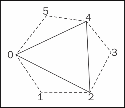
The geometry shader does the work of producing the silhouette shadow volumes. Since we are rendering using adjacency information (see the Drawing silhouette lines using the geometry shader recipe in Chapter 6, Using Geometry and Tessellation Shaders), the geometry shader has access to six vertices that define the current triangle being rendered and the three neighboring triangles. The vertices are numbered from 0 to 5, and are available via the input array named VPosition in this example. Vertices 0, 2, and 4 define the current triangle and the others define the adjacent triangles as shown in the following figure:
The geometry shader starts by testing the main triangle (0, 2, 4) to see if it faces the light source. We do so by computing the normal to the triangle (n) and the vector from each vertex to the light source. Then we compute the dot product of n and each of the three light source direction vectors (da, db, and dc). If any of the three are positive, then the triangle faces the light source. If we find that triangle (0, 2, 4) faces the light, then we test each neighboring triangle in the same way. If a neighboring triangle does not face the light source, then the edge between them is a silhouette edge and can be used as an edge of a face of the shadow volume.
We create a shadow volume face in the
emitEdgeQuad function. The points a and b define the silhouette edge, one edge of the shadow volume face. The other two vertices of the face are determined by extending a and b away from the light source. Here, we use a mathematical trick that is enabled by homogeneous coordinates. We extend the face out to infinity by using a zero in the w coordinate of the extended vertices. This effectively defines a homogeneous vector, sometimes called a point at infinity. The x, y and z coordinates define a vector in the direction away from the light source, and the w value is set to zero. The end result is that we get a quad that extends out to infinity, away from the light source.
We don't worry about drawing the caps of the shadow volume here. We don't need a cap at the far end, because we've used the homogeneous trick described above, and the object itself will serve as the cap on the near end.
In the third and final pass, we reset our stencil test to pass when the value in the stencil buffer is equal to zero using glStencilFunc. Here we want to sum the ambient with the diffuse + specular color when the stencil test succeeds, so we enable blending, and set the source and destination blend functions to GL_ONE. We render just a single screen-filling quad, and output the value from the texture that contains our diffuse + specular color. The stencil test will take care of discarding fragments that are in shadow, and OpenGL's blending support will blend the output with the ambient color for fragments that pass the test. (Remember that we copied over the ambient color using glBlitFramebuffer earlier.)
The technique described above is often referred to as the z-pass technique. It has one fatal flaw. If the camera is located within a shadow volume, this technique breaks down because the counts in the stencil buffer will be off by at least one. The common solution is to basically invert the problem and trace a ray from infinity towards the view point. This is called the z-fail technique or Carmack's reverse.
Care must be taken when using z-fail because it is important to draw the caps of the shadow volumes. However, the technique is very similar to z-pass. Instead of incrementing/decrementing when the depth test passes, we do so when the depth test fails. This effectively "traces" a ray from infinity back towards the view point.
I should also note that the preceding code is not robust to degenerate triangles (triangles that have sides that are nearly parallel), or non-closed meshes. One might need to take care in such situations. For example, to better deal with degenerate triangles we could use another technique for determining the normal to the triangle. We could also add additional code to handle edges of meshes, or simply always use closed meshes.
- The Drawing silhouette lines using the geometry shader recipe in Chapter 6, Using Geometry and Tessellation Shaders