
2.3
Computing with Coupled Relaxation Oscillators
N. Shukla, S. Datta, A. Parihar and A. Raychowdhury
Department of Electrical Engineering, The Pennsylvania State University, University Park,, PA, 16802, USA; Department of Electrical Engineering, University of Notre Dame, Notre Dame,, IN, 46556, USA
School of Electrical and Computer Engineering, Georgia Institute of Technology, Atlanta,, GA, 30332, USA
1 Introduction
Complementary metal-oxide-semiconductor (CMOS) transistors supporting the Boolean computational framework have been the backbone of modern computation, and have fueled the information technology revolution for the past four decades. However, there is a class of computing tasks, such as associative processing, which involves the determination of a degree of match (or association) between two quantities in multidimensional space, for which the Boolean approach consumes a significant amount of computing resources. Mathematically, the quantification of the degree of match between two quantities requires the calculation of a distance (using a suitable distance norm) between two points that represents the two quantities in a high-dimensional space. It turns out that the so-called “Boolean bottleneck” arises from the requirement of a significant number of power-intensive multiply–accumulate (MAC) operations involved in the calculation of the distance norm.
Associative computing-based applications such as pattern recognition, visual saliency, and image segmentation are becoming increasingly pervasive as we aim to design intelligent video analytic systems1 with the eventual goal of realizing a “visual cortex on a silicon platform,” to mimic human vision on a hardware platform. Consequently, the computational inefficiency of CMOS in associative computing, along with the increasing relevance of associative processing-based applications, motivates the development of an alternate non-Boolean computational approach.
In this chapter, we focus on our recent work in experimentally demonstrating tunable coupled relaxation oscillators, based on the phenomenon of insulator–metal transition in vanadium dioxide (VO2), as an efficient non-Boolean computational primitive capable of performing the visual saliency task. Our approach is an embodiment of “let the physics do the computing” paradigm and judiciously exploits the phase synchronization dynamics of pairs of coupled oscillators to compute a fractional distance norm that is suitable for associative computing.
2 Vanadium dioxide-based relaxation oscillators
VO2 is a transition metal oxide that exhibits an abrupt insulator-to-metal transition (IMT) at ∼340 K in its bulk single-crystal form. The insulating state (under no strain) has a monoclinic M1 crystal structure with an optically measured bandgap of 0.6 eV, which abruptly collapses into a metallic phase, accompanied by a structural transformation to the rutile crystal structure (with no bandgap).2 3 The abrupt collapse of the bandgap amplifies the free-carrier concentration and manifests itself as a sharp change in resistivity (up to five orders in magnitude in bulk single crystal). Further, the IMT in VO2 can be induced using temperature, as in Fig. 1(a), strain,4 doping,5 and electrical stimulus, as in Fig. 1(b). The phase transition can be triggered on ultrafast timescales (∼75 fs) as experimentally demonstrated by time-resolved optical pumping.6 However, the exact physics and the origin of the phase transition have been topics of debate for the past several decades; various models have been proposed to explain the IMT in VO2, attributing it to varying degrees of contribution from a Mott–Hubbard type correlated phase transition as well as from a Peierls-like structural instability.7 8

Figure 1 (a) Typical resistivity versus temperature characteristics of 10 nm thick VO2 films epitaxially grown on (001) TiO2; (b) Typical current–voltage characteristics of two-terminal VO2 devices (VO2 channel of 2 µm length, 10 µm width).
We can harness the electrically induced large, abrupt, and hysteretic change in resistivity of the VO2 to implement VO2-based relaxation oscillators by connecting a resistive load RS in series, as shown in Fig. 2(a). When a voltage is applied across the circuit so that the electric field across the VO2 device exceeds the critical field, E > E2, the IMT is triggered resulting in a negative differential resistance (NDR) characteristic.9 The NDR is characterized by a decrease in resistivity and a simultaneous reduction in the electric field across the VO2 device. If, as a result, the electric field across the VO2 drops below a critical value, E < E1, the metallic phase becomes unstable and the VO2 channel undergoes the metal–insulator transition (MIT) and returns to the insulating state with a corresponding increase in the electric field across the VO2. Subsequently, the process repeats itself in a self-sustaining manner, resulting in sustained electrical oscillations.

Figure 2 (a) Schematic of the two-terminal VO2 oscillator circuit; (b) Schematic of the I–V characteristics of VO2 device without RS (short dashed line). A series resistor modifies the I–V dynamics across the phase transition in VO2 (NDR load lines 1 and 2), leaving the circuit in either bistable or unstable oscillatory mode, depending on RS; (c) Typical time-domain waveform of the VO2 relaxation oscillator.
Representing this scenario through an electrical load line, as in Fig. 2(b), a VO2 device operating on load line 2 will oscillate, since the electric field across the VO2 channel drops below the critical field for MIT, whereas a device operating on load line 1 will not exhibit oscillatory behavior.9 The resulting representative time-domain waveform of the relaxation oscillator is shown in Fig. 2(c).
The properties of the oscillator such as frequency cannot be tuned with a constant RS, thereby constraining its utility in computational circuits. The tuning capability can be added by replacing the resistor RS with a metal-oxide semiconductor field-effect transistor (MOSFET) (drain of the MOSFET is connected to the VO2) and utilizing it as a voltage-controlled variable resistor, thereby creating a hybrid-vanadium dioxide metal-oxide semiconductor field-effect transistor (HVFET) oscillator,10 illustrated in Fig. 3. Modulating the gate-to-source voltage VGS of the MOSFET changes the resistance in series with the VO2 and changes the operating frequency of the oscillator. The voltage-controlled oscillator (VCO) function is shown in Fig. 3(c).

Figure 3 (a) Schematic of a VO2 relaxation oscillator consisting of a two-terminal VO2 device (channel length/width of 4/6 µm) in series with the source–drain of a MOSFET; (b) Time-domain waveform of the HVFET oscillator. (c) Oscillation frequency versus VGS, enabling VCO operation.
3 Experimental demonstration of pairwise coupled HVFET oscillators
To make such oscillators relevant to associative computing applications, we explore in detail their synchronization dynamics. Figure 4(a) illustrates the schematic of the capacitively coupled HVFET oscillators. The use of capacitive coupling is motivated by its high-pass filtering characteristics that block any DC interaction while simultaneously allowing for the exchange of reactive power among the oscillator pair, allowing the oscillators to synchronize.9 The resulting time-domain waveforms of the synchronized oscillators are shown in Fig. 4(b), while the corresponding power spectrum is shown in Fig. 4(c). Further, as shown in Fig. 4(d), the resonant frequency of the coupled oscillators can be tuned by modulating the input gate voltage difference ΔVGS = VGS,2 − VGS,1.10

Figure 4 (a) Schematic of the capacitively coupled HVFET oscillators (coupling CC = 2.2 nF); (b) Time-domain waveform of the synchronized coupled HVFET oscillators after eliminating DC offsets (VGS,1 = 1.25 V, VGS,2 = 1.3 V); (c) Power spectrum of the coupled waveform in (b); (d) Variation of coupled frequency as a function of ΔVGS = VGS,2 − VGS,1.
4 Computing with pairwise coupled HVFET oscillators
For performing computation, we investigate using simulations, the phase dynamics of the synchronized HVFET oscillators using the equivalent circuit illustrated in Fig. 5(a). Figure 5(b) shows the simulated voltage flow diagrams for the coupled oscillators (at different input gate voltages), as the individual oscillators in the coupled configuration traverse between their respective insulating and the metallic states.11 12 The simulations reveal that the shape of the periodic orbit in the phase space (i.e., the relative phase difference between the oscillators) is a strong function of the difference between the input voltages VGS,1 and VGS,2. For instance, when the gate voltage inputs to the two oscillators are equal, say VGS1 = VGS2 = 0.3 V, the oscillators have a high out-of-phase locking character, with only a small fraction of the periodic orbit lying in the phase space that represents in-phase locking (shown in gray in Fig. 5(b)). On the other hand, as the input voltage difference between the oscillators increases, the periodic orbit evolves to having a higher percentage of in-phase locking character.13

Figure 5 (a) Equivalent circuit of the capacitively coupled oscillators, where C1 and C2 are the equivalent capacitances of the VO2 devices combined with the respective MOSFET output circuits; (b) Effect of input gate voltages on the shape of the steady-state periodic orbit of the coupled oscillators; (c) Experimental; and (d) simulated time-averaged xor output of the oscillations as a function of ΔVGS.
This sensitivity of the periodic orbit of the HVFET oscillators can be harnessed for associative computing. By encoding the two quantities that need to be compared in the gate input voltages, the evolving periodic orbit of the coupled oscillators in phase space can be exploited to calculate the degree of match between them. To quantify the periodic orbit, we define a time-averaged xor measure by (i) thresholding the analog output to a binary stream, (ii) applying the xor operation on these binary values at every time instance, and, finally, (iii) averaging the xor output for a finite time duration (over at least three to four complete periodic orbits). This metric quantifies the degree of in-phase locking between the oscillators, and a higher value indicates higher in-phase locking in the periodic orbit. It is discernible from Fig. 5(b) that the time-averaged xor value is minimized when the two inputs are similar and the value subsequently increases with increased separation ΔVGS between the gate voltage inputs. This is confirmed through both experiments and simulations, compared in Fig. 5(c) and (d), indicating that a quantitative determination of the degree of match can indeed be performed using the pairwise coupled HVFET oscillators.
The pronounced similarity between the 2D contour map of the xor output of the oscillators with the function (xi1/2 − yi1/2)2, illustrated in Fig. 6, indicates that the specific distance norm calculated by the oscillators is the L0.5 “fractional distance norm.”
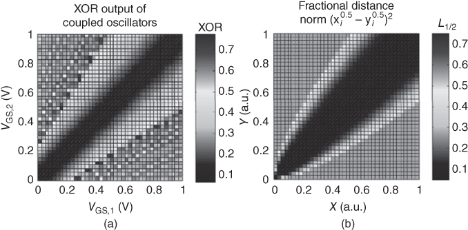
Figure 6 (a) Two-dimensional contour map of the time-averaged xor output of the coupled oscillators as function of VGS,1 and VGS,2; (b) The fractional distance norm L0.5 = (xi1/2 − yi1/2)2 suggesting that xor output of the oscillators computes a distance norm close to L0.5.
5 Associative computing using pairwise coupled oscillators
We investigate the inherent ability of the synchronization dynamics of the coupled oscillators to compute a distance norm for visual saliency determination. Visual attention/saliency is the property of the human brain by which certain aspects of an image are more important aka salient than other aspects of the same image.
Usually, objects in the image that have a high degree of contrast with their neighborhood are salient to the human brain. Figure 7(a) shows a sample image wherein the squirrel and the bark of the tree are more prominent in comparison to the details in the white background. To replicate this functionality with the coupled oscillators, edge detection is performed using an array of pairwise oscillators to approximate the degree of dissimilarity between a given image pixel and its immediate neighbors (distance computation) – see Fig. 7(b). Different edges such as vertical, horizontal, and diagonal are detected based on the selection of neighboring pixels for comparison. As this concept is expanded to include the comparison of pixels within a larger neighborhood (pixels surrounding reference pixel; a 3 × 3 neighborhood is used here), the output approximates the visual saliency (see Fig. 7(c)). For comparison, the same image is also evaluated using a 32 nm CMOS accelerator, as shown in Fig. 7(d) and (e).

Figure 7 (a) Input image processed by the oscillators; (b) Schematic of the processing scheme for visual saliency using coupled HVFET oscillators; (c) Output of the coupled oscillators; (d) Functional block diagram for the 32 nm CMOS accelerator-based processing scheme for finding the visual saliency; (e) Visual saliency output of the 32 nm CMOS accelerator.
The power-performance projection of the HVFET synchronized oscillator-based processing scheme was calculated to be ∼259 µW, as shown in Fig. 8(a). It can be observed that the oscillators performing as the fundamental distance computing functional block consume only 8 µW of power; the remaining power is consumed by the external peripheral circuitry required to read out the xor output of the oscillators. Thus, designing new power-efficient read-out schemes will enable further reduction in power. To evaluate if the oscillator-based computing approach provides a power-performance advantage, the total power requirements of the 32 nm CMOS-based accelerator in performing the same task were also evaluated and the total power consumption is measured to be ∼13.1 mW. Comparing the power requirements for the two computing approaches in Fig. 8(b), we find a substantial advantage (∼50× power reduction) in performance can be attained in associative computing applications using coupled HVFET oscillators.

Figure 8 (a) Power distribution among various functional blocks in the HVFET coupled-oscillator-based associative computing scheme for visual saliency; (b) Comparison of the power requirements with a CMOS implementation. The total power consumption is calculated to be 13.1 mW and 259 µW, respectively.
6 Conclusion
We have experimentally demonstrated coupled relaxation oscillators with input programmable synchronization that harness the insulator–metal transition in VO2. The phase dynamics of the synchronized oscillators can be used to calculate a fractional distance norm, thereby providing an alternative non-Boolean route to associative computing applications such as visual saliency and pattern matching. Coupled oscillator systems have the potential to achieve a significant advantage in power consumption over their CMOS counterparts in future video analytic applications.
References
- 1. V. Narayanan, S. Datta, G. Cauwenberghs, D. Chiarulli, S. Levitan, and P. Wong, “Video analytics using beyond-CMOS devices,” Proc. Design Automation Test Europe (DATE) Conf. (2014), pp. 1–5.
- 2. L. A. Ladd and W. Paul, “Optical and transport properties of high quality crystals of V2O4 near the metallic transition temperature,” Solid State Commun. 7, 425–428 (1969).
- 3. J. H. Park, J. M. Coy, T. S. Kasirga, et al., “Measurement of a solid-state triple point at the metal–insulator transition in VO2,” Nature 500, 431–434 (2013).
- 4. J. Cao, E. Ertekin, V. Srinivasan, et al., “Strain engineering and one-dimensional organization of metal–insulator domains in single-crystal vanadium dioxide beams,” Nature Nanotechnol. 4, 732–737 (2009).
- 5. X. Tan, T. Yao, R. Long, et al., “Unraveling metal–insulator transition mechanism of VO2 triggered by tungsten doping,” Nature Sci. Rep. 2, article no. 466 (2012).
- 6. A. Cavalleri, T. Dekorsy, H. Chong, J. Kieffer, and R. Schoenlein, “Evidence for a structurally-driven insulator-to-metal transition in VO2: A view from the ultrafast timescale,” Phys. Rev. B 70, 161102 (2004).
- 7. R. M. Wentzcovitch, “VO2: Peierls or Mott–Hubbard? A view from band theory,” Phys. Rev. Lett. 72, 3389–3392 (1994).
- 8. T. M. Rice and J. P. Pouget, “Comment on ‘VO2: Peierls or Mott–Hubbard? A view from band theory’,” Phys. Rev. Lett. 73, 3042 (1994).
- 9. N. Shukla, A. Parihar, E. Freeman, et al., “Synchronized charge oscillations in correlated electron systems,” Nature Sci. Rep. 4, article no. 4964 (2014).
- 10. N. Shukla, A. Parihar, M. Cotter, et al., “Pairwise coupled hybrid vanadium dioxide-MOSFET (HVFET) oscillators for non-Boolean associative computing,” Tech. Dig. IEDM (2014), pp. 28.7.1–28.7.4.
- 11. A. Parihar, N. Shukla, S. Datta, and A. Raychowdhury, “Synchronization of pairwise-coupled, identical, relaxation oscillators based on metal–insulator phase transition devices: A model study,” J. Appl. Phys. 117, 054902 (2015).
- 12. S. Datta, N. Shukla, M. Cotter, A. Parihar, and A. Raychowdhury, “Neuro-inspired computing with coupled relaxation oscillators,” Proc. Design Automation Conf. (DAC) (2014), pp. 1–6.
- 13. A. Parihar, N. Shukla, S. Datta, and A. Raychowdhury, “Exploiting synchronization properties of correlated electron devices in a non-Boolean computing fabric for template matching,” IEEE J. Emerg. Sel. Top. Circ. Syst. 4, 450–459 (2014).