

140 Game Development and Simulation with Unreal Technology
the vertices of the mesh on which the m aterial is applied with the same amount of
displacement. To have more control over the localities on the m esh, w e can supply a
texture through a Texture Sample input. If a texture is supplied to the World Po-
sition Offset channel, the effect of displacement will be calculate d from the texture
and applied to appropriate vertice s and location on the mesh.
Figure 4.14 shows how different values on the World Position Offset channel
affect the geometry of a mesh directly from the material. In this figure, the object on
the left has a mater ia l with no World Position Offset. The material applied to the
second object from the le ft has a Constant3Vector with values of (R:0.0, G:0.0,
B:10.0) applied to its World Position Offset channel.
FIGURE 4.15: Materials with the same Base Color and N ormal Maps (left) and with World
Displacement (right).
Notice that the RGB values affect the mesh’s vertices along the XYZ coordinates,
respectively. Therefore, all vertices of this mesh are pu shed 10.0 units upwards (i.e.,
along the positive value of the z-axis). It is important to note that using the World
Position Offset may r esult in the o bject to expand beyond its bound s. However, the
rendere r still uses the original bounds of the object. This may result in parts of the
object getting culled or in shadowing problems.
World Displacement
The World Displac ement Channel works similarly to the World Position Off-
set, but utilizes tessellation vertices rather than the object’s vertices to offset the
material. This channel can be utilized to make objects have true depth, rath er than
the simulated depth achieved by using a normal m ap alone.
Figure 4.15 shows two pairs of objects with the same Base Color and Normal
maps, with (the rig ht object) and without (the left object) World Displacement.
Notice how mu ch more ru gged the object to the right (with World Displacement)
is compared to the o bject w hich only h as its normal channel.
It is important to note tha t the rendered will still use the or iginal bounds of the
object, even when the object’s vertices are placed outside of the original bounds as a

Materials in Unreal Engine 141
FIGURE 4.16: A Tessellation has to be selected for the World Displacement Channel to
function.
result of applying the World Displacement to expand the object. This may result
in parts of the object being culled or getting shadowing error s.
One important fact to note is th at, this channel can only function if Tessellation
is activated. Figur e 4.16 shows how you can set the Tessell ation property of a
material node to someth ing other than NONE to activate the World Displacement
channel.
FIGURE 4.17: The network generating the World Displacement values for the rightmost
mesh in Figure 4.15.
Figure 4.17 shows the network that draws the World Displacement channel
of the rightmost material shown in Figure 4.15. Basically, the network takes the
perpen dicular value of the normal map, magnifies it and applies it to the normal
value drawn from a mesh vertex in the World Space. The resulting calculation is
then applied to the World Displacement channel of the material. The end effect of
this operation is to push the vertices that lay in the crevices down, while pulling the
rest of the vertices on the mesh outwards, giving some real geometric depth to the
object.
142 Game Development and Simulation with Unreal Technology
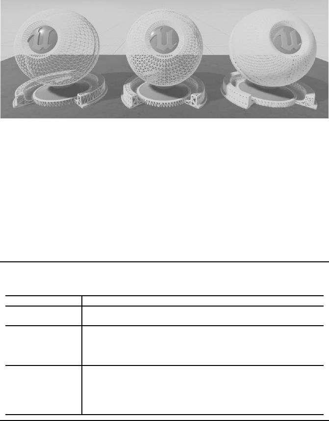
FIGURE 4.18: The effects of different values for t he Tessellation Multiplier Channel. Wire-
frame of the meshes are rendered to show the effect. The Tessellati on Multiplier value is
increased from left to right.
Tessellation Multiplier
The Tessellation Mu ltiplier Channel con trols the amount of tessellation on the
surface of an object. This will permit for details to be added o r removed from the
geometry. This channel is only enabled when Tessellation is activated (see Fig-
ure 4.16).
TABLE 4.2
Tessellation Settings
Tessellation Setting Description
None No Tessellation Applied. Tessellation Multiplier and World Displace-
ment channels will be disabled.
Flat This setting splits up triangles on each polygonal face of the surface. To
create new surface details you may use the W orld Position of the new
vertices by using the Normal map and the World Displacement chan-
nels.
PN Triangles This setting smoothens the object by utilizing the mesh’s smoothing group.
For this option to work properly, the mesh requires to have at least one
smoothing group. Much like the Flat option, the world displacement and
normal maps may be used to displace the newly tessellated vertices to
create much m ore details on the surface.
Tessellation is a DX 11 feature and requires hardware that supports DX11 . The
main functionality of tessellation is to split tr ia ngles into sma ller tr ia ngles at runtime.
This will have the benefit of increasing the surface detail of a mesh. However, effects
that require the use of tessellation can be very slow to render and should be used if
such realism is required .
Figure 4.18 shows the effect of the Tessellation Multiplier channel on the wire-
frame of the shown objects. The value of this channel is incre ased from left to right
in the figure. Notice how much more complicated the details on the rightmost object

Materials in Unreal Engine 143
(with a higher Tessellation M ultiplier) is compared to the leftmost ob je ct ( w ith much
lower values fo r the Tessellation Multip lier channel). By using both the Tessella-
tion Multiplier c hannel and the World Displacement channel you can create very
complicated geometry directly f rom your materials.
There are three Tessellation settings, as shown in Table 4.2. The table presents a
detailed description of each Tessellation option available on the Details Panel
of the material node in Unreal Engine’s material editor.
FIGURE 4.19: The effects of Subsurface Color channel on materials. F rom left: the first ma-
terial uses the Lit shading model and no subsurface color is active. The material on the second
mesh has the Subsurface shading model with nothing applied to its Sub surface Color chan-
nel. The third material has a red color (R:0.2, G:0.0, B:0.0) applied to its subsurface channel
with the same Base Color as the first material. The last material only has the red subsurface
color (as in the third material) but no Base Color.
Subsurface Color
The Subsurface Color Channel allows you to add a color or texture that shifts the
color of the material as lig ht passes thr ough the surface. This effect is similar to
“mother of pearl,” as you will see different colors dep ending on how you are looking
at the material. Note that this channel is only available when using a Sub surface
shading model (see Figure 4.20).
The subsurface shading model simulates the effect of subsurface scattering, a phe-
nomenon in which the light penetrates the surface of an object and diffuses through
it. Objects such as ice, wax and skin present this effect most visibly. To simulate this
effect, the subsu rface color allows th e light to pass through the m aterial and diffuse
the subsurface color of the material in the lighting calculations.
Figure 4.21 shows the effect of subsurface scatter on a material without the sub-
surface channel (left) and with the subsurface chann el (right). Notice how solid the
object to the le ft looks, as its lighting is calculated by the Lit shading model. This
does not allow for th e light to pe netrate the object, and all light rays that hit the sur-
face of the object reflect back or get absorbed by the object. The object to the right
uses the Subsurface shading model. As such, some of the light penetrates the ob-

144 Game Development and Simulation with Unreal Technology
FIGURE 4.20: Subsurface Color Channel is Available when the Material’s Shading Model
is Set to Subsurface.
ject and scatters below the surface, reflecting back the subsurface color of the object.
Notice how wax-like the object with subsurface scatter looks.
FIGURE 4.21: A Closeup View of Effects of the Subsurface Shading Model.
Clear Coat
The Clear Coat Channel is used to simulate a material that has a thin translucent
layer over the surface of the material, much like a clear coat over the surface of
acrylic paint. This can be used to achieve an acry lic or lacquer effect on the top of
the mater ia l. In order to u se this material c hannel, the material shading model should
be set to Clear Coat shading model.
The Clear Coat Shading Model simulates the e ffect of multilayer materials
with a th in translucent layer of film over the surface of the Material. This model
can be used on both m etal and non-metal materials. You can use the Clear Coat
channel with the Clear Coat Roughness channel to simulate many multilayered
materials and effect.
You must use either the value of 0 or 1 for the Clear Coat ch annel. The amount
of 0 acts like a standard material without a clear coat applied to it. The value of 1
..................Content has been hidden....................
You can't read the all page of ebook, please click here login for view all page.