

Advanced Material Concepts in Unreal Engine 279
to a particle. However, like all other parameters in Unreal Engine, it can be refer-
enced and its values changed in an instance of the material at run-time, by level
designers, or by the other engine components such as Cascade and Matinee.
TABLE 5.15: Texture Sample Parameter SubUV Properties
Parameter Name: Specifies the name use d to identify the parameter in
instance of the material and through code.
Group: Provides a way to organize parameter names into grou p s, or cat-
egories, within a M aterial Instance Constant. All parameters
within a material that have the same Group property n a m e will be
listed underneath that category in the instance.
Texture: Specifies the texture sampled by the expression.
Sampler Type: The type of data that will be sampled and output from
the node.
Mip Value Mode: Applies a noise value to the texture that affects the
look and performance.
TABLE 5.16: Texture Sample Parameter SubUV Inputs
UVs: Takes in UV texture coordinates to use for the texture. If n o val-
ues are input to the UVs, the texture coordinates of the mesh the
material is applied to are used.
TABLE 5.17: Texture Sample Parameter SubUV Outputs
RGB: Outputs the three-channel RGB vector value of the color.
R: Outputs the red channel value of the color.
G: Outputs the green channel value of the color.
B: Outputs the blue channel value of the color.
A: Outputs the alpha chan n e l vector value of the color.
CROSS-REFERENCE
To learn more about visual effects through Particle Systems and the Cascade
Particle Editor, check out Chapter 6, Section 6.3 on page 304 to learn about
the Cascade Particle System Editor in detail.

280 Game Development and Simulation with Unreal Technology
5.4.2 PARTICLE EXPRESSIONS
These expressions
4
act as a bridge between the Material Editor and Cascade Particle
System Editor. This link allows for a dynamic intera ction between material compo-
nents and those of per-particle based particle systems. Expressions in this category
include Particle Color, Particle Direction, Particle Radius, Particle Size, Dynamic
Parameter, Particle M acroUV, a nd so on [ 43]. Here we will explain a few common ly
used Particle Expressions an d leave a c omprehensive referen ce to A.
Particle Color: This expression must be a part of the network that is plugged into
the appropr ia te channel (e.g., Emissive Color). The expression creates a link be-
tween the Unreal renderer an d the particle systems and makes it possible to control
any per-particle d ata with in Cascade.
FIGURE 5.3: Particle Color Expression Example.
TABLE 5.18: Particle Color Outputs
RGBA: Outputs the RGBA vector data.
R: Outputs the red channel data.
G: Outputs the green channel data.
B: Outputs the blue channel data.
A: Outputs the alp h a channe l data.
Example Usa ge: Connecting the RGBA outpu t ch annel o f this expr ession to the
Emissive Color and a network driving from its alpha channel to the opacity
channel of a material will expose th e color of the mate rial to the particle
system. You can then manipulate the color, alpha, color over life, and alpha
over life of each particle in an emitter from Initial Color and Color Over
Life m odules in the cascade editor ( see Figure 5.3).
4
The contents of this section are adopted from the official UE4 online documentation found at:
https://docs.unrealengine.com/latest/INT/.

Advanced Material Concepts in Unreal Engine 281
Particle Direction: This expre ssion creates a link between the Unreal renderer and
the particle systems and makes it possible to control the color of any per-particle
data from the loc ation of each particle in the world. This expression must be a
part of the network th at is plugged into the appropriate material cha nnel (e.g.,
Emissive Color).
FIGURE 5.4: Particle Rotation Expression Example.
Example Usa ge: Connecting the RGBA output channel of this exp ression
through a network to the Emissive Color channel of a material will expose
the ro ta tion of each particle to the emissive color of the material. You can
then manipulate the orientation of each particle in an emitter to chan ge the
emissive color of their material (see Figure 5.4).
Particle Ma cro UV: This expression outputs UV texture coordinates that ca n be
used to map any 2D texture onto the entire particle system in a continuous
way. This will make the texture appear seamless across p articles. The UVs
will be centered around the MacroUVPosition with the MacroUVRadiu s. The
MacroUVPosition and the MacroUVR adius can be found under the Macro UV
section of the Details rollout of the Required emitter module.
The Particle Macro UV expression is u seful for mapping con tinuous noise onto
particles to break up the pattern introduced by m apping a texture onto each pa rti-
cle with normal texture coordin ates. Note: As of Unreal Engine 4.5, this expres-
sion is not compatible with GPU particle systems.
Example Usa ge: Create a Particle Macro UV expression and connec t its out-
put ch annel to the UVs input channel of a Texture Sample exp ression. Set
the texture of this Text ure Sample expression to the texture you would like
to map a s the back drop of your particle effect. Connecting the RGBA output
channel of the Texture Sample expression to the Emissive Color channel
of the material will create the effect shown in Figure 5. 5.

282 Game Development and Simulation with Unreal Technology
FIGURE 5.5: Particle Macro UV Expression E xample.
Particle World Position WS: This expression exposes each particle’s position in
the world space coordinate to the mate rial. You may use the output of this ex-
pression in a network to drive various aspects of particles’ material. Note: This
expression works on a per-p article basis.
FIGURE 5.6: Particle Position Expression Example.
Example Usa ge: Create a Particle World Position exp ression and connect its
output channel to a network that cr eates a 3Vector representing a color based
on the position of each particle in the world space. Connec ting the result of
this network to the Emissive Color chan nel of a material node will create
particles whose color will change based on their position in the world space
as shown in Figure 5.6.
One important note to keep in mind is that this expression will return the
actual world space position of each particle in the material editor. As a result,
if the emitter is moved in the world, th is will impact the position of sp awned
particles. This should be compensated for in a network within the m aterial
editor to avoid undesirable effects.
Particle Radius: This expression exposes eac h particle’s radiu s to the material. You
may use the output of this expression in a network to drive various aspects of
particles’ material. Note: This expression works o n a per-particle basis.
Advanced Material Concepts in Unreal Engine 283
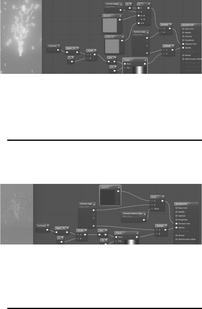
FIGURE 5.7: Particle Radius Expression Example.
Example Usa ge: Create a Particle Radius expression and connect its output
channel to an If expression to pick between two colors based on the radius
of each particle. Connecting the result of this network to the Emissive Colo r
channel of a material node will create particles whose color will change
based on their radius as shown in Figure 5.7.
Particle Relative Time: This expression exposes each particle’s relative time (i.e.,
a particle’s age as a number between 0 and 1) to th e material. You may use the out-
put o f this expression in a network to drive various aspects of particles’ material.
Note: This expression works on a p er-particle basis.
FIGURE 5.8: Particle Relative Time Expression Example.
Example Usa ge: Create a Particle Relative Time expression and connect its
output channel to the alpha channel of a Lerp expression to pick between
two colors based on the relative age of each particle. Connecting the result
of this network to th e Emissive Color chan nel of a material node will create
particles whose color will change as they age (see Figure 5.8).
..................Content has been hidden....................
You can't read the all page of ebook, please click here login for view all page.