
Visual Effects and Cascade in Unreal Engine 331
and use values from Figure 6.24(b).
16. At this stage of the work , you shou ld be able to see the performa nce of your
particle emitter in the simulation preview w indow – Figure 6.25(a). However, this
is not quite the right effect for rain. Rain droplets should be genera te d over a large
area not fro m a single point. We will do exactly this, in the next step.
17. Save your progress.
SETTING UP THE RAIN PLANE
If you have closed the Cascade Particle E ditor, double-click on the P_Rain
particle system in the content browser to open it in the e ditor. Now we will set
up the distribution for the spawning of the rain particles, so that they will spawn
from a plane instead of a single point.
18. Right-click under the last emitter module (it should be the Lifetime module),
and choose the Location ◮ I nitial Location module to add it to your par-
ticle emitter.
19. In the Initial Location module d etails panel, expand the Start Location, and
the Distribution sections. E nter the value of 300 for the Max , and -3 00 for the
Min values for both X and Y components of the Distributio n.
Min = [X:-300, Y:-300, Z:0] Max = [X:300, Y:300, Z:0]
(a) (b) (c)
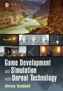
FIGURE 6.25: (a) The Rain Emitter spewing droplets from one point. (b) The Rain Emitter
spawning rain droplets over a two-dimensional plane. (c) Rain Emitter Actor shown in the
level.
20. This will make the particle em itter spawn rain droplets over a plane that spans
from (−300,−300, 0) to (300, 300, 0) in space – Fig ure 6.25(b ).
21. Place the P_Rain emitter actor in the level, by dragging a copy o f it from the con-
tent browser onto the demo display item. Position the emitter actor at the center,
and towards the top of the demo display item in the level – Figure 6.25(c ).
22. Save your progress so far. T his particle em itter has certain aspects of simulating
rain, but it looks far from over. In particular, we would like to have the rain drop
at an angle (as if there was some wind affecting the rain). M oreover, the droplets
332 Game Development and Simulation with Unreal Technology
of rain are pe rfectly spherical. We would like the rain droplet to be elonga te d to
simulate the effect of the drag force of the atmosphere on them.
SIMULATING WIND AND ATMOSPHERIC DRAG FORCE
Double-c lick on the P_Rain particle system you created in the last section to
open it in Cascade Particle E ditor.
23. The first thing to do, to simulate the effect of the atmospheric drag force on the
rain particles is to change the Screen Alignment of the p articles in the Required
emitter module.
24. Click on the Required modu le and its details panel change its Screen
Alignment to PSA_Velocity.
25. Right-click under the last emitter module (it should be the Initial Location
module), and choose the Size ◮ Size By Speed module to add it to your par-
ticle emitter.
26. Click on the Size By Speed module. In this modu le ’s de ta ils panel, make the
following changes:
SpeedScale = [X : 1.0,Y : 3.0] MaxScale = [X : 1.0 , Y : 3.0]
27. As shown in Figure 6.26(a) the particles are too big to be rain droplets. This is
because we are scaling the initial size of the particles up along the Y axis of
their velocity path. Let us make the fo llowing changes to the Sta rt Size ◮
Distribution of the Initial Size mod ule of the emitter – see r esults in Fig-
ure 6.26(b):
Max = [X : 10.0, Y : 10.0,Z : 10 .0] Min = [X : 5.0, Y : 5.0, Z : 5.0]
(a) (b) (c)
FIGURE 6. 26: (a) The rain droplets are scaled along their speed path. (b) The rain droplet
sizes after changing their initial size. (c) Rain Emitter Actor shown in the level. (c) Rain
particles affected by gravity and wind forces.

Visual Effects and Cascade in Unreal Engine 333
28. One thing about this rain effect that is still not quite right is the way the rain
droplets fall to the groun d. We have used an Initial Velo city module to g ive
the drop le t particles a start speed. As rain droplets have some mass, they are af-
fected by a number of forces. Two of these for ces are the earth’s gravity, and
the wind. To simulate th ese forces, we will add an Acceleration module to the
emitter.
29. Make the following changes to the Acceleration ◮ Distribution parame-
ters in th e details panel of the Acceleration Module:
Max = [X : 60.0,Y : 0.0,Z : −98.0] Min = [X : 60 .0,Y : 0.0, Z : − 98.0]
30. You will notice that after adding the acceleration modu le and applying the forces
to our particles, they tend to speed up as time goes by. This will make them exit
our field of view, and therefore a few of the rain particles are now visible. We
need to increase the num ber of these particles being spawned .
31. Click on the Spawn module of the emitter and change the constant value of its
Spawn ◮ R ate ◮ D istribution to 90.0:
Constant = 90.0
32. Save your progress and the level. Rain particles should now look like Fig-
ure 6.26(c).
What Happened in TUTORIAL 6.3. . .
In this tutorial you set up a visual effec ts system to simulate rain using a simple
sprite emitter.
SPRITE MATERIAL
The particle material is just like a regular material. However, instead of a color
parameter or constant value, we used a Particle Color node to drive the color
of our particle system’s sprites from the color modules of the emitter. This node
has the benefit of exposing the color of the sprites within the Color Modules of
the Emitter to which this material is applied. This way, we can control the initial
color and color over life o f sprites within the Emitter module.
The mate rial expression network is shown in Figure 6.22(b). To make the ma-
terial translucent, we set the Shading Model of the material to Unlit, and its
Blend Mode to translucent. Since the shading mod el for the material is set to
Unlit, we can program the shading of the mater ia l v ia its Emissive Color chan-
nel. The output o f any expression we plug into this node will drive the shading
of the material. So let us see how we achieved this:
•
Rain Material’s Emissive Color: The effect that we are trying to achieve requires
the material’s color to be fully visible at center of the particles and fade away as
334 Game Development and Simulation with Unreal Technology
we get closer to their boundaries. To achieve this, we can use a function (i.e., a
Material Expression node) that has a disk shape – i.e., it goes from 1 to 0 by
distance from the center as shown in Figure 6. 17(a).
Unreal Material Edito r has a material expression called Radial Gradient Ex-
ponential. It simulates a circle in 2D with f ull value ( equal to 1) at the center,
dropping its value to 0 as the distance grows from the center.
We could just multiply the output of the Radial Gradie nt Exponential ex-
pression with the Particle Color RGB values and assign it to th e emissive channel
of our sprite ma te rial. Our material would look like Figure 6.17(a).
•
Material’s Opacity: The opacity cha nnel of the material uses the same cal-
culations as the emissive color. We multiply the output of the Alpha chan -
nel of the P article Color module with the output of the Rad ial Gradient
Exponential expression to calculate opacity – see Figure 6.22(b).
RAIN INITIAL PARAMETERS
After setting u p and assigning the Rain Sprite’s material, it is tim e to set the
particle system up. As we discussed earlier in this chapter, a visual effect is made
of one or more Particle Emitters. Each emitter, in turn, is made of two or more
modules. If you remem ber, the Required and Spawn modules are manda tory
modules and must be present in each emitter. Most other modules can be add ed
later on; such as, initial control mod ule, or overtime module .
For this Rain sprite em itter, we added five initial modules, four initial modules,
and one lifetim e module.
•
Initial Color: We set the RGB values of the initial color to be (1,1, 1). Therefore,
all of our particles will have a white color when they spawn.
•
Lifetime: The lif etime module controls the m inimum and ma ximum possible life-
time of each emitted sprite. We set the minimum value of the lifetime distribution
to be 5, a nd maximum to be 10 . With these values, each emitted sprite is assigned
a lifetime of 5 to 10 seconds. The particle dies after its lifetime expires.
•
Initial Siz e: We assigned an initial size between (15,15,15) and (25, 25,25) to
each spawned particle through this module. This should give a nice randomness
to the shapes of the spawned sprites.
•
Initial Velocity: To create more randomness for the look of our visual e ffect, we
use another d istribution fo r the initial velocity of our particles. Wh en a particle
is about to spawn, unreal will pick its initial velocity between the minimum and
maximum values we set up for it. Since velocity is a vector in 3D – i. e., x, y, and
z– we set two vectors for initial velocity. In this example we set the minimum
speed of a rain droplet to be be tween [−10,−10,−50] and [10,10 , −30]. Notice
that sinc e the rain drops, we give negative values to the Z component of the min
and max speed vectors.
The variations in the x and the y axes of the initial speed m ake the pa rticles to
travel in a random trajectory – see Figure 6.25(a).
•
Initial Location: The problem so far with the particle system for rain is that it
looks like rain drop le ts are all being generated from one point in space – Fig-

Visual Effects and Cascade in Unreal Engine 335
ure 6.25(a). However, we can simulate the real rain drop over a region by cre-
ating an Initial Location module within our rain particle emitter. As shown
in Figure 6.27(a) the initial location module basically allows the emitter to draw
the spawn location of each particle from the volume enclosed within the Sta rt
Location distribution.
(a) (b)
FIGURE 6.27: (a) Particles will be spawned somewhere w ithin the Initial Location
rectangular cube. (b) In our example the clouds are assumed to be located at a plane.
In our tutorial, we assumed th at the clouds ar e lo cated over an area spanning a
600 × 600 rectangle. We set the minimum values of the Start Lo cation distri-
bution to [−300, −300,0] and its m aximum value to [300, 300 , 0] – Figure 6.27(b).
SETTING UP FORCES AFFECTIN G RAIN DRO PLETS
After setting u p our rain particle system to spawn rain drops from a plane, we
need to make the effect look realistic. The first part of this realistic effect is to
simulate the elasticity of rain p articles. As rain droplets fall, they are subject to
the air which puts a drag f orce on them. This for ce makes the droplets stretch
along their falling pa th. Thankfully we can achieve this effect relatively easy,
and with little computational cost to o ur CPU.
The emitter we are using is a sprite emitter. As such, each particle is basically
a 2D bitmap (also called a sprite). The Required module of a sprite emitter has a
component called Scr een Alignment. This compone nt controls how each sprite
is aligned with respect to the world and the viewer camera.
Table 6.3 describes how each Screen Align ment type may affect the orien-
tation and scaling of pa rticle sprites. The default m ode is PSA Square, which
orients the sprites towards the camera and uses a uniform scale for their size.
Since we are simulating rain drops, which are liquid, we need to use a non-
uniform scaling factor as well as add th e ability to or ie nt the droplets along their
motion pa th. We do this by chang ing the Screen Alig nment of the Requi red
module of the e mitter to PSA Velocity in step 24.
Now that we have selected the appropriate Screen Alignment, we need to
scale the rain drops non-uniformly by their speed. To do this we added a Size
..................Content has been hidden....................
You can't read the all page of ebook, please click here login for view all page.