Working with paths
Understanding anchor points and control handles
Drawing paths with the Pencil and Pen tools
Using the line tools
Using the Paintbrush tool
Working with other brushes
In this chapter, you learn about paths, which are the basic lines that make up the various objects. This chapter also covers using Illustrator's drawing tools, including the Pen, Pencil, and Paintbrush tools, to create these paths. And I talk about the techniques behind many cool effects that you can create by using these tools.
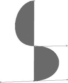
The most basic element in Illustrator is a path. A path is what Illustrator calls the black line segment that appears when you draw a line. When you select a path, its anchor points appear. A path must have at least two anchor points, which appear as small squares along the path and control which way the path goes. Paths look different in Preview and Outline modes. In Preview mode, you actually see the line weight, dashed style, color, and any effects applied to that line. In Outline mode, you simply see a thin line. Without two anchor points, you can't draw a path like the one shown in Figure 4.1. Conceptually, there's no limit to the number of anchor points or segments that you can have in any one path. Depending on the type of anchor points that are on either end of a line segment, you can make a segment straight or curved. A single anchor point never prints anything.
Note
For more on Preview and Outline modes, see Chapter 2. For more on selecting paths, see Chapter 6.
Now that you know what a path is, you should understand the three major types of paths:
Open paths: Two distinct endpoints, with any number of anchor points in between. An example of this is a simple line that you draw with the Pencil tool.
Closed paths: Continuous paths, with no endpoints and no start or end — a closed path just continues around and around. An example of this is a shape that you create with one of Illustrator's shape tools, such as a rectangle or a circle.
Compound paths: Two or more open or closed paths.
Note
For more on creating shapes in Illustrator, see Chapter 5. For more on compound paths, see Chapter 12.
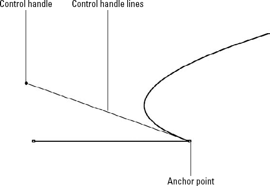
As stated earlier, paths consist of a series of points and the line segments between these points. These points are commonly called anchor points because they anchor the path; paths always pass through or end at anchor points. Anchor points are automatically created as part of a path; no path can exist without anchor points to define it.
Anchor points consist of control handles and control handle lines. Control handles, which appear as small squares along the path, determine how sharply or gradually the curve bends at each anchor point. Control handle lines run on a tangent along the path and are attached to the path by the control handle. They determine the direction of the curved path. The next section discusses control handles and control handle lines in more detail. Anchor points, control handles, and control handle lines don't appear on the printed output of your artwork. In fact, they appear only in Illustrator and Photoshop, never on artwork imported into other applications.
There are two classes of anchor points:
Smooth: These anchor points have a curved path flowing smoothly through them. Most of the time, you don't know where a smooth point is until you select a path. Smooth points keep the path from changing direction abruptly. Every smooth point has two linked control handles.
Corner: In this class of anchor points, the path changes direction noticeably at those specific points. There are three different corner points:
Straight: These are anchor points where two straight line segments meet at a distinct angle. There are no control handles on this type of anchor point.
Curved: These are points where two curved line segments meet and abruptly change direction. Each curved corner point has two independent control handles. Each handle controls a curve, and you can change only one side if you want.
Combination: These are the meeting places for straight and curved line segments. A combination corner point has one independent control handle. The one control handle controls the curve.
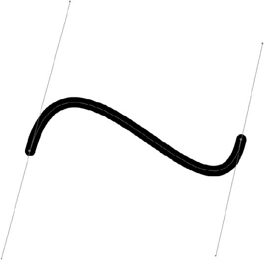
Figure 4.2 shows the different types of anchor points in Illustrator.
If an anchor point has a control handle coming out of it, the next segment is curved. No control handle, no curve. Couldn't be simpler.
As stated before, control handles are connected to anchor points with control handle lines. Figure 4.3 shows what happens when an anchor point with no control handle and an anchor point with a control handle are connected to another anchor point. Figure 4.4 shows the anchor points, control handles, and the control handle lines on a path.
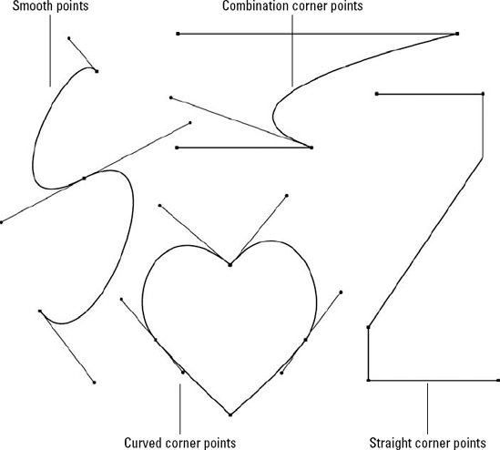
Figure 4.3. An anchor point without a control handle and an anchor point with a control handle are connected to new anchor points, resulting in a straight line segment and a curved line segment.
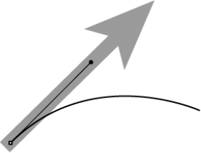
The basic concept to remember about control handles is that they act as magnets by pulling the curve toward them. This presents an interesting problem because each curved line segment usually has two control handles. Just as you might suspect, the control handle exerts the greatest amount of force on the half of the curved segment nearest to it. If there's only one control handle, the segment curves more on the side of the segment with the control handle than on the side with no control handle.
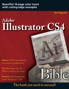
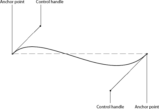
The greater the distance between a control handle and its corresponding anchor point, the farther the curve (on that end of the curve segment) pulls away from an imaginary straight segment between the two points. If the control handles on either end of the segment are on different sides of the curved segment, the curved segment takes on a reversed S shape, as shown in Figure 4.5. If the control handles on the ends of the curved segment are on the same side, the curve takes on a U shape.
Regardless of whether the anchor point is a smooth point, a curved corner point, or a combination corner point, control handle lines coming out of an anchor point are always tangent to the curved segment where it touches the anchor point. Tangent refers to the touching of the control handle line to the curved segment as it crosses the anchor point, as shown in Figure 4.6.
Tip
To adjust the curves without moving the control handles, click the curve and then drag it. Keep in mind that you're changing both control handles at once, which can make adjusting the curve hard to control.
If paths are the basic concept behind Illustrator, you may be wondering where the colors and patterns fit in. You apply all colors and patterns to Illustrator paths using fills and strokes. Basically, a fill is a color or pattern that appears within a path, and a stroke is a special style that you apply along a path.
Note
For more on applying available fills and strokes to shapes, see Chapter 5. For more on creating custom fills and strokes, see Chapter 10.
You should remember from Chapter 2 that when you work in Illustrator in Outline mode (View
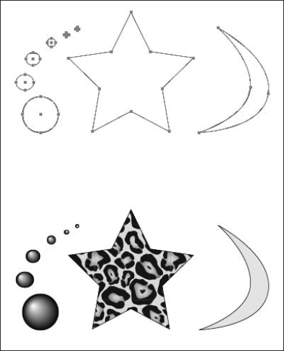
Figure 4.7. Closed paths with different fills: The top row shows how they appear in Outline mode, while the bottom row shows what they look like in Preview mode.
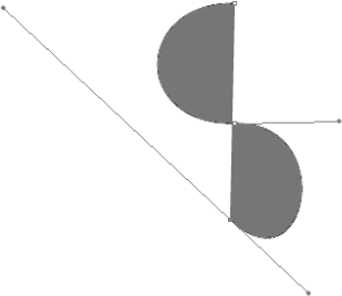
You can also fill open paths. The fill goes straight across the two endpoints of the path to enclose the object. Figure 4.8 displays different types of filled open paths. Filling an open path is usually not desirable, although in some circumstances, doing so may be necessary. Because the fill goes from the endpoints of the path, if you have an irregular-shaped path, the fill can look strange. If you're looking to create a cool pair of sunglasses, use a filled path for an unusual look.
Warning
A straight line with a fill can cause problems when you go to print. In PostScript, when you specify a fill but only have two dimensions to an object (a straight line), it prints (rasterizes) at 1 device pixel. At 100% on-screen, the filled line looks exactly like a 1-point stroked line (72 dpi = 1 device pixel = 1/72 inch and 1 point = 1/72 inch). When you zoom in to 200%, the stroked line scales by 200%, but the filled line stays the same (1 device pixel or 1/72 inch). When you print this line to a typical laser printer, 1 device pixel is as tiny as 1/300 or 1/600 inch. By the time you print to a typical imagesetter printer, 1 device pixel becomes 1/2570 inch, making it too small to be visible in most situations. The key to fixing it is to ensure that any paths you don't want filled have a fill of None before sending the document to print.
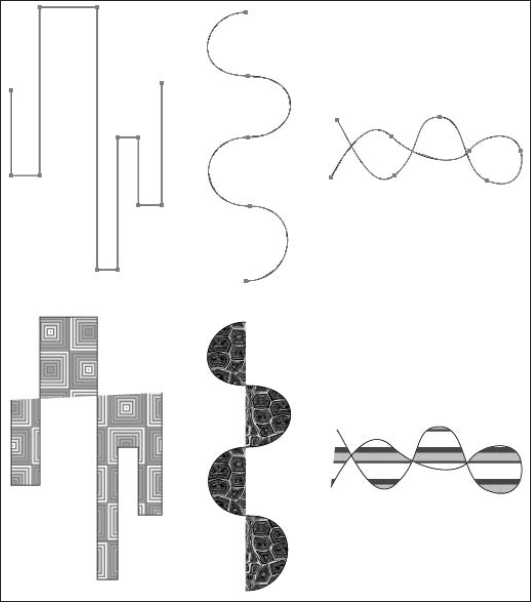
Figure 4.8. Open paths with different fills: The top row shows how they appear in Outline mode, while the bottom row shows how they appear in Preview mode.
Besides filling paths, you can also stroke paths with a tint of any color or a pattern. These strokes can be any weight (thickness), and the width of the stroke is equally distributed over each side of the path. Open paths have ends on the strokes; these ends can be cropped, rounded, or extended past the end of the stroke by half the width of the stroke. Several different paths with strokes are shown in Figure 4.9.
Note
For more on printing, see Chapter 18. For more on stroke weight, color, and attributes, see Chapter 5.
A single point is also considered a path; however, single points in Illustrator have no printable qualities. This isn't readily noticeable because you can assign a fill or stroke color to a single point, although you can't see it in Preview mode or when you print it. When the document is color-separated, it causes a separation of the color to print, even if nothing else on that page uses that same color, and the separation appears blank.
Tip
If you think that you may have individual anchor points floating around your illustration, you should select all of them at once by choosing Select
Fills and strokes in Illustrator can be colors (including an opaque white), which knocks out any color underneath. Fills and strokes can also be transparent. Transparency in Illustrator is commonly referred to as a fill, a stroke, or None.
Note
For more on color separations, see Chapter 18. For more on transparency, see Chapter 7.
The most effective (and challenging) way to create paths is to draw them with one of the drawing tools. The Pen, Pencil, and Paintbrush tools are the most common drawing instruments, but Illustrator also has a Brushes panel, including three key brushes — the Art Brush, the Scatter Brush, and the Pattern Brush. If you're looking for the Calligraphic option, you find it as a brush option that you can choose in the Brushes panel. The Smooth tool and the Path Eraser tool are two other helpful tools. They're located in the Pencil tool's popup menu. These two tools cut editing time drastically by letting you clean up lines and fix errors with the stroke of a brush.
Of the three main tools used to draw paths in Illustrator, the Pen is the most difficult to use, but it often yields the best results. The Pencil is by far the easiest but requires some editing to smooth the bumpy lines. The Paintbrush tool combined with a tablet can create some amazing hand-drawn looks in your art.
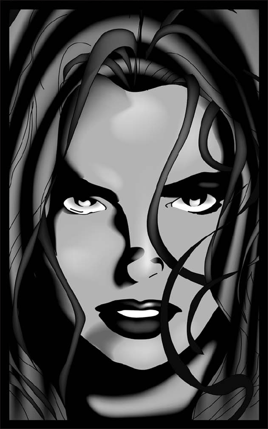
Each tool has its place, and you use all three to achieve the most productivity. So, practice using all the tools to find which one works best for whatever you may want to achieve. Figure 4.10 shows an illustration created using several different tools.
When you want to draw rough edges or realistic illustrations that don't look computery — for example, a map drawing with beautiful bumpy edges — the Pencil tool is the one to use. The Pencil tool is housed in the Tools panel with the tools that edit it — the Smooth and Path Eraser tools — and draws a free-form stroked path wherever you click and drag the cursor. However, instead of creating a closed path that's a certain width, the result is a single path that approximately follows the route you take with the cursor. The Pencil tool has the unique capability to make the lines you draw look ... well ... good.
Actually, part of the Pencil tool's charm is also its biggest drawback. Unlike the Pen tool — which creates precise, super-smooth lines but is difficult to control — the Pencil tool is much easier to use, but it draws lines that are far from perfect. This is because the Pencil tool creates only smooth points and corner anchor points. When you select the Pencil tool's anchor point, two control handles appear. If you remember the earlier discussion on anchor points, you know this means that you can neither draw a smooth anchor point — although at first glance, you may think you can — nor a straight corner point with the Pencil tool. This makes the construction of precise objects nearly impossible.
Before you use the Pencil tool for the first time, you should change the paint style attributes to a fill of None and a stroke of 1-point Black. Having a fill other than None while drawing with the Pencil tool often results in bizarre-looking shapes. To choose these settings, begin in the color section near the bottom of the Illustrator Tools panel. Click the Fill square and then click the None (red slash) box to ensure the fill is None. Select the stroke (outlined rectangle) and then choose Black to ensure the stroke has a black stroke. Choose Window
To use the Pencil tool, follow these steps:
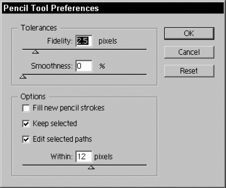
Double-click the Pencil tool. The Pencil tool is the tenth tool down in the Tools panel and is housed with the Smooth tool and the Path Eraser tool (which are discussed later in this chapter), which help smooth and edit Pencil tool paths. The Pencil tool, obviously, has a pencil for its icon. Double-clicking this icon opens the Pencil Tool Preferences dialog box, as shown in Figure 4.11.
Adjust the options in the Pencil Tool Preferences dialog box. The options are as follows:
Fidelity: The Fidelity setting controls how far (measured in pixels) curves may stray from the original dotted line that appears as you draw with the mouse. A low fidelity value results in sharper angles; a high fidelity value results in smoother curves. The lowest Fidelity number is .5 pixels, the highest is 20 pixels, and the default is 2.5 pixels.
Note
As stated previously, although you think you can create them at first glance, you can't create smooth anchor points. You may find this especially deceiving when you set Fidelity to a high number so that all the anchor points look like they're smooth points. This isn't the case. In fact, most anchor points created with the Pencil tool — with the exception of endpoints — are curved corner points, which are anchor points with two independent control handles shooting out.
Smoothness: Measured as a percentage, the Smoothness value determines how well the Pencil controls the bumpiness or irregularity of the line. A low Smoothness value results in a coarse, angular path, while a high Smoothness value results in a much smoother path with fewer anchor points.
Fill new pencil strokes: Applies a fill to new pencil strokes when clicked and applies no fill when deselected.
Keep selected: This option keeps the last path you drew selected in case you want to edit or do any changes right after drawing the path.
Edit selected paths: If you click this check box, you can edit the path with the Pencil tool. If you don't click this check box or if you deselect it, you can still edit, but you have to use the selection tools.
Within pixels: This value sets how close your drawing has to match the existing path to be editable; this works only when you click the Edit selected paths check box.
Click OK. Illustrator applies your preferences when you start using the Pencil tool.
Begin dragging the mouse. The Pencil tool resembles a little pencil when you're drawing. As you drag, a series of dots follows the cursor. These dots show the approximate location of the path you've drawn. The location of a path drawn with the Pencil tool is directly relevant to the speed and the direction in which the cursor moves.
Tip
Pressing Caps Lock (engaging it) changes the cursor from the Pencil shape to crosshairs. The line of points comes from the dot in the center of the crosshairs. Use the crosshairs if you want to see exactly the point from which the drawing starts. You can set your cursors to always be crosshairs just by opening the Preferences dialog box (by pressing Ctrl+K [

Release the mouse button. The path of dots is transformed into a path with anchor points, all having control handle lines and control handles shooting off from them. The faster you draw with the Pencil tool, the fewer points that are created; the slower you draw, the more points that are used to define the path.
Tip
You can repeat the item you just drew quickly and easily. Using the Selection tool, click the object you drew and then press Alt (Option). Next, drag the item elsewhere on the Artboard to make a copy of the original object. For more on the selection tools, see Chapter 6.
Tip
Using the Smooth tool, you can instantly transform a swooping, uneven, jagged line that looks terrible as you draw into a beautifully curved piece of artwork reminiscent of lines drawn traditionally with a French curve.
You can draw both open and closed paths with the Pencil and Pen tools. Paths in Illustrator may cross themselves. When these paths cross, the fills may look a little unusual. Strokes look normal; they just overlap where paths cross.
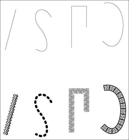
To create an open path, draw a path with the Pencil or Pen tool, but ensure that the beginning and end of the path are two separate points at different locations. Open paths with fills may look a little bizarre because Illustrator automatically fills in between the endpoints on the path, even if the imaginary line between the endpoints crosses the path. Figure 4.12 shows both open and closed paths drawn with the Pencil tool.
To create a closed path, end your path at the same place that you started the path. While drawing, press Alt (Option). When the Pencil cursor is directly over the location where the line begins, a little circle appears to the lower right of the Pencil. This change means that the path is a closed path if you release the mouse button when that particular cursor is showing.
You can quickly connect the Pencil paths you draw in Illustrator. While drawing with the Pencil tool, press Alt (Option), and when you release the mouse button, a line automatically connects the beginning anchor point to the ending anchor point, resulting in a closed path. You can try to draw back to the beginning line, but they probably won't connect. You can also draw the paths close to one another: Select the two endpoints and then press Ctrl+J (
To continue drawing on an existing path (which could have been drawn with the Pencil tool or the Pen tool), the existing path must first be an open path with two distinct endpoints. Pass the Pencil tool over one end of the path and then watch for the cursor to change — the little x beside the Pencil disappears. This action means that if you click and drag, you can extend the path with the Pencil tool. If Caps Lock is engaged, the cursor changes from an X (crosshairs) to a +.
You can add on only to endpoints on an existing path. Anchor points that are within paths can't be connected to new (or existing, for that matter) segments. If you attempt to draw from an anchor point that isn't an endpoint, you create an endpoint for the path you're drawing that's overlapping but not connected to the anchor point you clicked.
This extremely cool editing tool makes changing any path a breeze. The Smooth tool works on any path regardless of what tool created it. You can apply the Smooth tool in one of two ways:
Using the Tools panel: Select the path you want to edit, click the Smooth tool found in the Pencil tool's popup tools, and then drag your mouse over a selected path to smooth out the line.
While using other tools: You can also access the Smooth tool while using the Pencil tool by pressing Alt (Option). The tool changes to the Smooth tool while you keep Alt (Option) pressed.
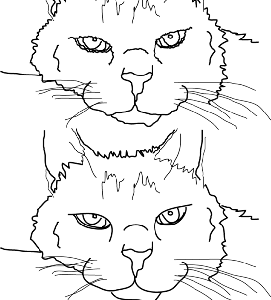
Figure 4.13 shows a path before and after using the Smooth tool. The top path has more anchor points than the smoothed bottom path.
Double-clicking the Smooth tool opens a dialog box where, just as with the Pencil tool, you can set Fidelity and Smoothness values.
You find the Path Eraser tool with the Pencil tool in the Tools panel. Like the Smooth tool, the Path Eraser tool works on any path, no matter how you created it. The Path Eraser tool does what its name suggests: It erases a path at the point where you've dragged the Path Eraser tool over the path. You can use the Path Eraser tool to cut a path by first selecting the path and then dragging across a section with the Path Eraser tool. Illustrator removes the section you drag over. You can use the Path Eraser tool to cut a line, just as you would use the Scissors tool. If you just click one time on the path, Illustrator cuts the path exactly in that spot. Unlike Photoshop's clunky eraser-looking tool, this is much more refined and easier to use.
Note
For more on the Scissors tool, see Chapter 6.
The Pen tool is the most powerful tool in Illustrator's arsenal because you're dealing more directly with Bézier curves than with any other tool. Drawing objects with any other tool is one thing, but using the Pen tool to create paths out of nothing is dumbfounding.
During the first several months of using Illustrator, you may find yourself avoiding the Pen tool like the plague. Then, you slowly work up to where you can draw straight lines comfortably and, finally, curved segments. Even after you draw curved segments for a while, you still may not understand how the tool works, and you may miss out on many of its capabilities because of that lack of knowledge. While practicing with the Pen tool, you begin to understand the four types of anchor points — smooth points, straight corner points, curved corner points, and combination corner points — and you discover that understanding how anchor points work is the key to using the Pen tool. The first click of the Pen tool produces one anchor point. The second click (usually in a different location) creates a second anchor point that's joined to the first anchor point by a line segment. Clicking without dragging produces a straight corner point.
Although the Pen tool is a little frustrating and confusing to use at first, it's the most important tool to learn. It saves you so much time and effort because you can draw the most accurately and smoothly with fewer edits. After you master this tool, you will use it for most of your drawing and tracing needs.
Unfortunately, the Pen tool doesn't do all the work; you do have to perform some of the labor involved in creating curves and straight lines. Drawing with the Pen tool isn't just placing anchor points.
Here are some issues to consider when you're drawing with the Pen tool:
The first obstacle is determining where the heck those anchor points are going to go. Two drawings with the same number of anchor points can look totally different, depending on anchor point placement. You have to think ahead to determine what the path will look like before you draw it. You should always locate points where you want a change in the path. That change can be a different curve or a corner. Look for these three changes:
The second obstacle is deciding what type of anchor point you want to use. Remember that you have four different anchor points to choose from when drawing with the Pen tool — smooth, straight corner, curved corner, and combination corner. If the path is smoothly curving, you use a smooth point. If it has a corner, use one of the corner points.
The third obstacle arises when you decide that the anchor point should be anything but a straight corner point because all the other anchor points have control handles. The obstacle is figuring out how to drag the control handles, how far to drag them, and in which direction to drag them.
The easiest way to start learning to use the Pen tool is by drawing straight lines. The lightning bolt in Figure 4.14 uses only straight lines. The great thing about straight lines drawn with the Pen tool is that you don't have to worry about or fuss over control handles.
The simplest straight line is a line drawn with only two anchor points. To draw straight lines, follow these steps:
Click the Pen tool. This tool is located on the third row of the first column in the Tools panel and looks like an old-fashioned ink pen tip.
Click and release where you want the first endpoint to appear. This becomes the beginning of your line.
Click and release where you want the second endpoint (the end of the line) to appear. A line appears between the two points. Too easy, isn't it?
Tip
Hold Shift to keep the line constrained to a 45° angle (0, 45, 90, etc.).
To draw another separate line, first click the Pen tool in the Tools panel or hold Ctrl (

Clicking and releasing again in one spot and then another draws a second line with two endpoints. Be careful not to drag when clicking the Pen tool to form straight lines. If you drag the mouse, you create a smooth point and the path curves.
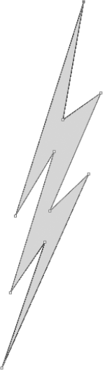
Figure 4.14. Straight lines drawn with the Pen tool are all you need to create something like this lightning bolt.
Paths drawn with the Pen tool, like the Pencil tool, may cross themselves. The only strange result you may see involves the fills for objects whose paths cross. In open paths created with the Pen tool, fills may look unusual because of the imaginary line between the two endpoints and any paths that the imaginary line crosses.
If you want to create a closed path (one with no endpoints), after you finish whatever you're drawing, hover over the first anchor point in that segment. As the Pen tool crosses over the beginning anchor point, the cursor changes to a pen with a circle in the lower-right corner. Click the mouse on this anchor point to close the path. After you create a closed path, you don't need to click the Pen tool again. Instead, the next click of the Pen tool in the document automatically begins a new path.
Initially, you may find the whole process of drawing curves with the Pen tool rather disorienting. You actually have to think differently to grasp what the Pen tool is doing. To draw a curve, you need to drag with the Pen tool rather than click and release when you draw straight lines. This section gives two sets of instructions for creating two basic curve shapes: the bump and the S shape.
The most basic curve is the bump (a curved segment between just two points). Follow these steps to create the bump that's shown in Figure 4.15:
Click with the Pen tool and then drag up about ½ inch. You see an anchor point and a control handle line extending from it as you drag.
Release the mouse button. When you do so, you see the anchor point and a line extending to where you dragged, with a control handle at its end.
Position the cursor about 1 inch to the right of the place you first clicked.
Click with the mouse and then drag down about 1/2 inch. As you drag, you see a curve forming that resembles a bump.
Release the mouse. The curve fills with the current fill color. You also see the control handle you just dragged.
Before you try to draw another curve, remember that the Pen tool is still in a mode that continues the current path; it doesn't start a new one. To start a new path, choose Select
To create an S shape, one more set of steps is needed. With these steps, you can create the S shape, as shown in Figure 4.16:
Click and drag with the Pen tool about ½ inch to the left. An anchor point and a control handle line appear as you drag.
Release the mouse button. You should see the anchor point and the control handle that you just drew, with a control handle line between them.
Position the cursor about 1 inch below where you first clicked.
Click and drag to the right ½ inch.
Release the mouse button.
Position the cursor about 1 inch below the last point you clicked.
Click and drag to the left about ½ inch. Now you have an S shape.
Note
For more on changing strokes and fills, see Chapter 6.
All the anchor points created in these two exercises are smooth points. You drag the control handles in the direction of the next curve that you want to draw. The lengths of the control handle lines on either side of the anchor point are equal. However, you don't have to make the lengths of the control handle lines on either side of the smooth point the same. Instead, you can make a smooth point have both long and short control handle lines coming out of it. The length of the control handle line affects the curve, as shown on the S curve in Figure 4.17.
Follow these steps to create a smooth point with two control handle lines of different lengths:
Create a smooth point along a path. See the last set of steps to learn how to do so.
Select the newly created smooth point with the Direct Selection tool. For more on using the selection tools, see Chapter 6.
Click and drag the control handle again.
Adjust the angle for both control handle lines and the length for the new control handle line that you're dragging. Note that as you drag out this control handle line, the other control handle line wobbles to the angle that you're dragging. This happens because on any smooth point, the control handle lines must be at the same angle, and as you drag out the new control handle line, you're simultaneously changing the angle for both control handle lines.
The majority of the paths you draw with the Pen tool will be closed paths, not the open ones you've drawn so far. Like open curved paths, any closed curved path must have at least two anchor points, just as paths with straight corner points need three distinct points to create a closed path.
When the Pen tool is placed over the starting point of the path you've drawn, a little circle appears to the right of the pen shape. This indicates that the path becomes a closed path if you click this anchor point.
Of course, to ensure that the initial anchor point remains a smooth point, you need to click and drag on the initial anchor point. Simply clicking produces a combination corner point, which has only one control handle associated with it.
Curved corner points are points where two different, usually distinct, curved segments meet at an anchor point. Because the two curves meet this way, a smooth point doesn't provide the means for their joining correctly. Instead, a smooth point would make the two different curves smoothly blend into each other.
The main difference between a curved corner point and a smooth point is that a smooth point has two linked control handles on their ends; a curved corner point has two independent control handles. As the name indicates, control handles and their associated control handle lines move independently of each other, enabling two different, distinct types of curves to come from the same anchor point.
To create a curved corner point, create a smooth point in a path, press Alt (Option), and then drag the control handle of the point you just created. As you do this, you're creating the control handles independently. The next segment will curve as controlled by the newly split control handle, not by the original combined one.
Tip
When creating curved corner points, you can press Alt (Option) to create independent points all the time, not just when starting a new segment.
A combination corner point is a point where a curved segment and a straight segment meet each other. At this corner point, there's one control handle coming from the anchor point from the side where the curved segment is located, and on the other side, there's no control handle, indicating a straight segment.
To create a combination corner point with the Pen tool, draw a few curved segments and then go back to the last anchor point. You should see two linked control handles displayed at this point. Simply click once on the anchor point, and one of the two control handles disappears. The next segment then starts out straight.
Tip
You can change existing smooth and curved corner points into combination corner points simply by dragging one of the control handles into the anchor points.
Now that you've gained some experience with the Pen tool, you'll benefit by living by the Pen Rules. The Pen Rules are laws to live by — or at least to draw by.
Follow these rules:
Remember not to drag where you want to place the next point; instead, go just one-third of that distance. You must determine where you want to locate the next anchor point before you can determine the length of the control handle line you're dragging. Dragging by one-third is always a good approximation to make. You may run into trouble when the control handle line is more than half or less than one-quarter of the next segment. If your control handle line is too long or too short, chances are good that the line will curve erratically.
Don't get the outside of the curve and the outside of the shape you're drawing confused — they may well be two different things. Remember that control handle lines are always tangent to the curved segment they're guiding. Tangent? Well, here's a simpler way of putting this rule: It's a line that touches the curve but doesn't cross or intersect the curve. If your control handle lies inside the curve you're drawing, it becomes too short and overpowered by the next anchor point. Control handles pull the curve toward themselves; this makes them naturally curve out toward the control handle lines. If you fight this natural pull, your illustrations can look loopy and silly.
Drag the control handle in the direction that you want the curve to travel at that anchor point. The control handle pulls the curve toward itself by its very nature. If you drag backward toward the preceding segment, you create little curved spikes that stick out from the anchor points. This commandment applies only to Smooth points. If the anchor point is a curved corner point, you must make the initial drag in the direction the curve is traveling and the next drag (Alt [Option]+drag) in the direction that you want the curve to travel. If the anchor point is a combination curve point and the next segment is straight, make the dragging motion in the direction that the curve is traveling. Next, click and release the anchor point. If the combination curve point's next segment is curved, click and release the first click, and the second click should be dragged in the direction of the next curve.
Use as few anchor points as possible. If your illustration calls for smooth, flowing curves, use very few anchor points. If, on the other hand, you want your illustration rough and gritty, use more anchor points. The fewer anchor points you use, the smoother the final result. When only a few anchor points are on a path, changing its shape is easier and faster. More anchor points mean a bigger file and also longer printing times. If you're not sure whether you need more anchor points, don't add them. You can always add them later with the Add Anchor Point tool.
Note
For more on the Add Anchor Point tool, see Chapter 6.
Place anchor points at the beginning of each different curve. You should use anchor points as transitional points, where the curve either changes direction or increases or decreases in size dramatically. If it looks as though the curve changes from one type of curve to another, the location to place an anchor point is in the middle of that transitional section.
Don't overcompensate for a previously misdrawn curve. If you really messed up on the last anchor point you've drawn, don't panic and try to undo the mistake by dragging in the wrong direction or by dragging the control handle out to some ridiculous length. Doing either of these two things may temporarily fix the preceding curve but usually wrecks the next curve, causing you to have to overcompensate yet again.
In addition to the Pencil and Pen tools, Illustrator includes several unique tools that you can use to create specialized types of lines. From straight lines with the Line Segment tool to spiral lines using the Spiral tool, these line tools fall into the convenience category. Housed with the Line Segment tool, these tools include the Arc, Spiral, Rectangular Grid, and Polar Grid tools.
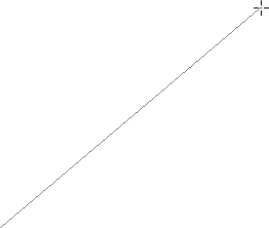
Now that you've learned how to create straight lines the hard way with the Pen tool, here's an easy way — use the Line Segment tool. After you learn to use the Line Segment tool, you'll think that using the Pencil or Pen tool to draw straight lines is just plain ridiculous. Any amount of caffeine in your system results in a jittery line with either tool. But using this tool is a breeze. Simply click and drag the line where you want it to go, as indicated in Figure 4.18. Holding Shift while drawing a line constrains the line to 45° increments. If you press Alt (Option) while drawing a line, your starting point begins in the middle of the line.
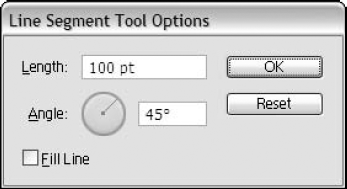
Double-clicking the Line Segment tool or clicking one time on the Artboard displays the Line Segment Tool Options dialog box, as shown in Figure 4.19. In this dialog box, you can set the length and angle and whether to fill the line with the defaulted fill color. You can use the Pen tool to draw straight lines, but when you have a tool specifically made for lines, use it.
Tip
The Pen tool versus the Line Segment tool: The Pen tool can also draw straight lines and constrained lines, so why use the Line Segment tool at all? Well, one small slip of the Pen tool and you have a curved line. In addition, you can get the precise length and angle using the Line Segment tool because you actually see the line rubberbanding from the original point.
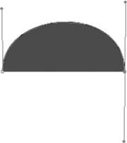
Arcs are now easily drawn using the Arc tool. The old-fashioned way used to be to draw an oval and remove the sections you didn't need via the Direct Selection tool or the Scissors tool. Figure 4.20 shows an arc drawn with the Arc tool.
The Arc tool is housed with the Line Segment tool. You can have an arc that sweeps inward or outward, depending on your settings. Double-clicking the Arc tool accesses the Arc Segment Tool Options dialog box, as shown in Figure 4.21.
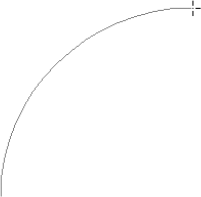
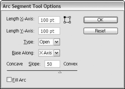
Figure 4.21. The Arc Segment Tool Options dialog box includes several options for the properties of an arc.
These are the Arc Segment Tool Options:
Length X-Axis: Type the value for the length of the slope along the x-axis.
Length Y-Axis: Type the value for the length of the slope along the y-axis.
Type: Choose whether you want the arc to have an open or closed path.
Base Along: This is where you choose the direction of the slope, either along the x-axis or the y-axis.
Slope: Dragging the slider to the left results in a concave slope. Dragging the slider to the right results in a convex slope.
Fill Arc: Clicking this check box fills the inside of the arc with the default color.
Tip
When dragging out an arc, pressing F or X toggles the arc between convex and concave. Press the spacebar while you draw to move the whole arc. These keyboard shortcuts are true with all shapes that you draw in Illustrator.
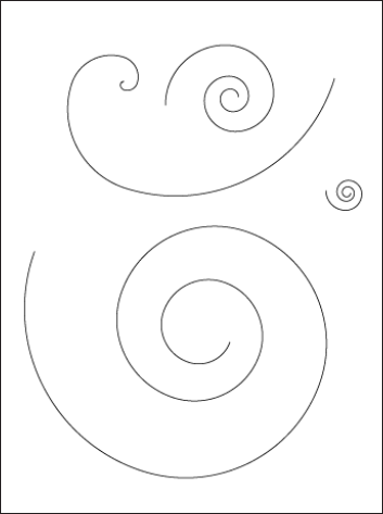
The Spiral tool (located with the Line Segment tool) makes spirals — all sorts of spirals. What can you use a spiral for? Well, you can use the Spiral tool to create a simulated record. Of course, the path is exceedingly long and refuses to print on most imagesetters. Other than that, you can use them to simulate nature patterns, such as snails, shells, a whirlpool, or a cinnamon roll. Figure 4.22 shows several spirals manufactured with the Spiral tool.
Tip
Spirals beg to be stroked, not filled. Putting just a fill on a spiral makes it look lumpy and not quite round.
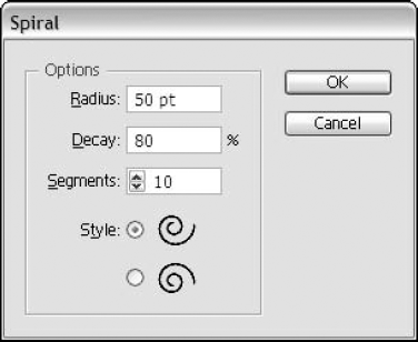
If you click in your document with the Spiral tool, the Spiral dialog box, as shown in Figure 4.23, opens, and you can type specific values for a spiral. This is handy for those times your client or boss wants that 82.5% decay spiral. Decay measures how tight the spiral is, while Segments controls the length of the spiral.
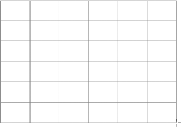
You can easily create a grid using the Grid tool, which is housed with the Line Segment tool. For example, you could use a grid to create a perspective drawing. Use the Skew tool to give an angled view. You can create a unique Rubik's cube. You can also create grid paper or use the Grid tool to create a data chart. Figure 4.24 shows a drawn grid.
Pressing these keys while creating rectangular grids makes life easier:
Up or down arrow: Increases or decreases the number of horizontal lines
Left or right arrow: Increases or decreases the number of vertical lines
Shift: Creates a perfect square grid
Alt (Option): Creates a grid from a central point
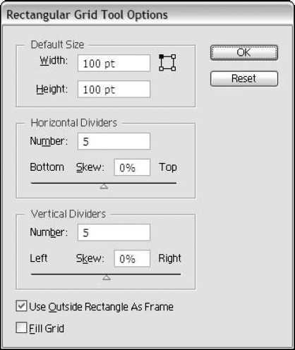
Double-clicking the Grid tool accesses the Rectangular Grid Tool Options dialog box, as shown in Figure 4.25. Under the Grid Options, you can choose to skew the grid. That is, you can make the lines closer to the top or bottom and left or right. You can change the following options:
Default Size: Type the width and height in points.
Horizontal Dividers: Type how many dividers and how much they will skew.
Vertical Dividers: Type the number of dividers and how much they will skew.
Use Outside Rectangle As Frame: This option causes a rectangle to frame the grid.
Fill Grid: Clicking this check box fills the grid with the default fill color.
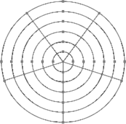
The Polar Grid tool is found with the Line Segment tool. A polar grid is also referred to as a radar grid. You would recognize it as similar to a dartboard or a bull's-eye, as shown in Figure 4.26.
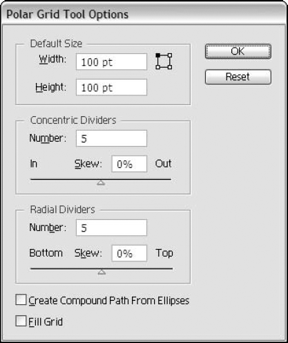
The Polar Grid Tool Options dialog box, as shown in Figure 4.27, lets you set the same options as those found in the Rectangular Grid dialog box, except that the dividers are concentric and radial instead of horizontal and vertical:
Default Size: Type the width and height in points.
Concentric Dividers: Type how many dividers and how much they will skew (distributed) away from the center.
Radial Dividers: Type the number of dividers and how much they will skew from top to bottom.
Create Compound Path From Ellipses: Choosing this option causes ellipses to create a compound path, which is treated as a single path by Illustrator and results in a bull's-eye effect for the grid.
Fill Grid: Clicking this check box fills the polar grid with the default fill color.
Pressing these keys while creating polar grids makes life easier:
The Paintbrush tool draws a stroked path — that is, a path that's also a brushstroke. This makes life so much easier when it comes to editing. The Paintbrush tool is similar to paintbrush-type tools in painting programs. The Paintbrush has a certain width, and you can paint with this Paintbrush at this width anywhere in your document. The big difference between the paintbrushes in paint programs and Illustrator's Paintbrush tool is that when you finish drawing with Illustrator's Paintbrush tool, you create a stroked path.
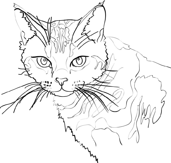
To use the Paintbrush tool, click the tool, choose the brush from the Brush panel, and then start drawing. A free-form path appears wherever you drag. That's all there is to it — mostly. Figure 4.28 shows a drawing that was created with the Paintbrush tool set to a variable width with a pressure-sensitive stylus.
Drawing with the Paintbrush tool is a bit more complicated than I just explained. The most important consideration is the width of the paintbrush stroke. The paintbrush stroke can be as narrow as 0 points and as wide as 1296 points (that's 18 inches to you and me).
Although 0 is the smallest width, a paintbrush stroke drawn with a width of 0 points actually has a width bigger than 0 points. To change the paintbrush stroke width (the default is 9 points), open the Stroke panel (not the Tools panel) and then type a number in the Weight text field. Remember that you're actually changing the default brush.
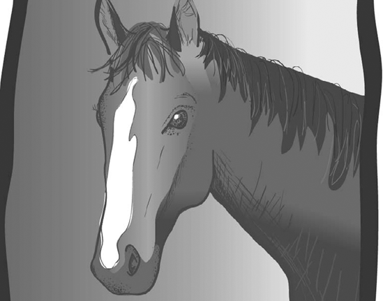
Figure 4.28. This drawing of a horse was created with the Paintbrush tool by using a pressure-sensitive tablet and a stylus.
A mouse is not an intuitive drawing tool, and not being able to draw in the first place makes it even more difficult to draw with the Paintbrush tool. So, if artists have trouble with the mouse, what's the point of having the Paintbrush tool at all? Well, instead of a mouse, you can use several types of alternative drawing devices. The best of these is a pressure-sensitive tablet (for more information about pressure-sensitive drawing tablets, visit the Wacom Web site at www.wacom.com). Trackballs with locking buttons are also good for drawing with the Paintbrush tool; this allows more control over the direction and speed of the Paintbrush.
Tip
When you're drawing with any of the tools in Illustrator, dragging off the edge of the window causes the window to scroll, which creates a frightening effect for the uninitiated. If you don't want the window to remain where it scrolled to, don't let go of the mouse button; instead, drag in the opposite direction until the window returns to the original position.
To help you draw more precisely, you have the option of changing the cursor shape from the cute little brush into crosshairs. Press Caps Lock (to engage it), and the cursor changes into crosshairs with a dot in the center. Press Caps Lock again (to release it), and the cursor returns to the brush shape. The dot at the center of the crosshairs is the center of any paintbrush stroke drawn with the Paintbrush tool. Normally, when the cursor is in the shape of a paintbrush, the tip is the center of the paintbrush stroke. Some people find it easier to draw when the Paintbrush cursor is replaced with the precise crosshairs.
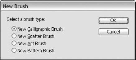
If you want to create a totally new brush, choose New Brush from the Brushes panel's popup menu to display the New Brush dialog box, as shown in Figure 4.29. You can then choose the type of new brush you want to create. You can choose from Calligraphic, Scatter, Art, and Pattern brushes. The Brushes panel includes samples of each of these brush types. Calligraphic brushes make strokes similar to a calligraphic pen. Scatter brushes scatter an object along the brushed path. The Art brush takes an object and stretches it along the brush path length. The Pattern brush uses repeated tiles along the brush path.
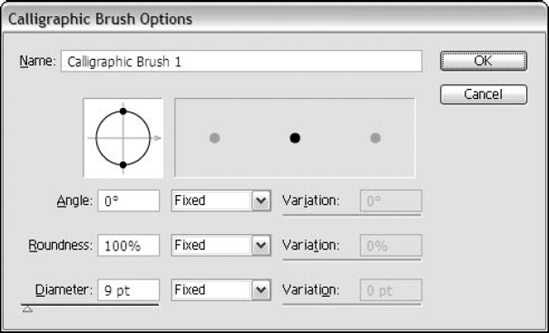
A Calligraphic brush was made to simulate an actual calligraphic pen tip. You set the angle and size and then draw to your heart's content. You can also create a perfectly round brush in the Calligraphic Brush Options dialog box by not typing an angle and by keeping the roundness at 100%.
The Calligraphic Brush Options, as shown in Figure 4.30, are as follows:
Name: You can type a name here for your new brush or rename an existing brush (maximum of 30 characters).
Angle: You can set the angle of the Calligraphic brush. The angle you should choose depends on what's going to be drawn. To mimic hand-drawn lettering in a calligraphic style, the angle should be set to 45° (or if you're left-handed, it should be set to −45°).
Roundness: This does what you think it does. It sets the roundness of the brush. The higher you make the value, the rounder the brush.
Diameter: The diameter value sets the maximum diameter of the brush.
Variation: If you choose the Random option from the Angle or Roundness dropdown lists, you can then type a value for Variation. The Variation for the Angle value is in a degree that you want to vary from the original setting for each brushstroke. The Variation for the Roundness is set in percentages. A slider sets the Variation for the Diameter or you can type a number. The Diameter Variation goes from your original value up to the Variation value. This is a great way to simulate a hand-drawn look if you don't have a pressure-sensitive tablet.
You can use a Calligraphic brush in many ways. You can choose an existing brush and get started. If you load additional brush libraries, you'll find quite a variety of brushes to choose from. You can also create your own brush from an existing one or from scratch. To create a new brush, use an existing style that you like but that you want to alter. To create a brush like this, choose the brush that you want to duplicate and then choose Duplicate Brush from the Brush panel's popup menu. To edit that duplicated brush, double-click the duplicate brush or choose Brush Options from the popup menu. In the Brush Options dialog box, change the brush to your specifications.
If you have a pressure-sensitive tablet — some call them Wacom (pronounced walk 'em) tablets because a large majority are made by Wacom — you can choose the Pressure option beside the Diameter text field in the Brush Options dialog box (accessed by double-clicking a brush in the Brushes panel). If you don't have a pressure-sensitive tablet, the Pressure option is grayed out.
Note
A pressure-sensitive tablet is a flat, rectangular device over which you pass a special stylus. The more pressure exerted by the stylus on the tablet, the wider a paintbrush stroke becomes, provided that you choose the Pressure option in the Calligraphic dialog box. When using the Pressure option, try to set the Variation different from the original specified diameter to see the difference when you press harder or softer.
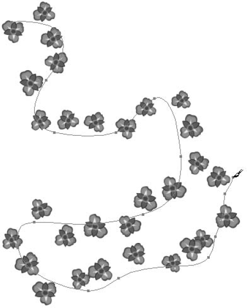
The Scatter brush copies and scatters a predefined object along a path. Illustrator has a number of brush libraries containing artwork that you can use for a Scatter brush or you can choose a piece of artwork that you created to use as a Scatter brush. Choose Window
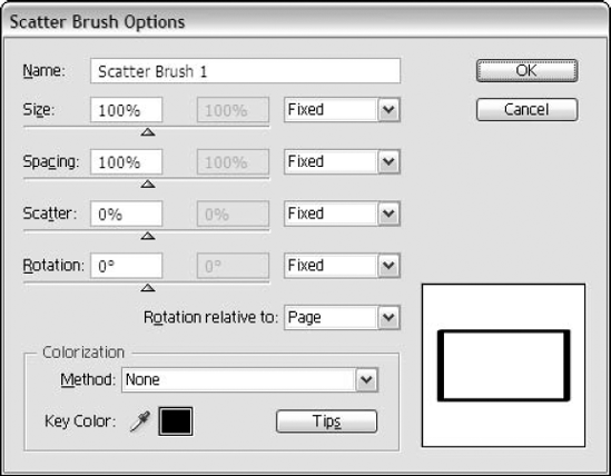
These are your choices in the Scatter Brush Options dialog box, as seen in Figure 4.32:
Name: You can type a name for your brush (up to 30 characters).
Size: In the size area, you have several options. If you want really big images and small images that vary in size, then drag the sliders in opposite directions (there are two there, even though you can't see them when you first create the brush).
Spacing: This option adjusts the space between each object.
Scatter: This option adjusts how the objects follow the original path on each side of the path. If you set a high value, the objects are farther away from the original path.
Rotation: This option adjusts how much the object rotates from its original position.
Rotation relative to: This option gives you two choices from a popup menu. The Page option rotates objects according to the page setup. The Path option rotates objects tangent to the path.
Colorization: You have four Colorization choices: None, Tints, Tints and Shades, and Hue Shift. Colorization and tips about colorization can be found later in this chapter.
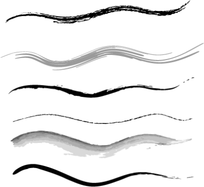
The Art brush, like the Scatter brush, uses an object along a path. The difference is that the Art brush stretches the object to the length of the path rather than repeating and scattering the object. Illustrator centers the object evenly over the path and then stretches it. Figure 4.33 shows several Art brush examples.
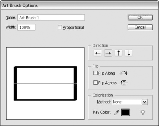
These are your choices in the Art Brush Options dialog box, as shown in Figure 4.34:
Name: You can type a name your new Art brush or rename an existing Art brush (up to 30 characters).
Width: This value scales the art when it's stretched. You can choose Proportional to keep the object in proportion.
Direction: This option lets you choose from four directions. The directions are relative to how you drag the Paintbrush.
Flip: This option lets you flip your object along or across the path.
Colorization: You have four Colorization choices in the Method popup menu: None, Tints, Tints and Shades, and Hue Shift. The key color is the color that the colorization uses as a base. Colorization and colorization tips can be found later in this chapter.
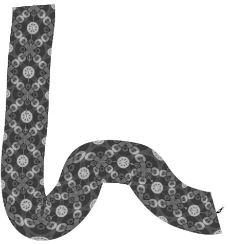
The Pattern brush repeats a tiled object along a path. The Pattern brush can have tiles to display the sides, inner corner, outer corner, beginning, and end. If you think of a Pattern brush as you would a regular pattern tile but keep in mind the corners, you'll have no problem creating your own interesting Pattern brushes. Figure 4.35 shows an example of one of the Pattern brushes.
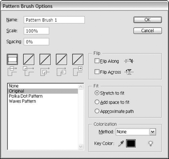
These are your choices in the Pattern Brush Options dialog box, as shown in Figure 4.36:
Name: Type a new name or change an existing name (up to 30 characters).
Scale: This option allows you to increase or decrease the size of the pattern relative to its original size.
Spacing: This is the space between each tile of the pattern.
Tile buttons: This is where you choose which of the five tiles you want to create.
Flip: This option lets you flip the pattern along or across the path.
Fit: In this option, you can choose Stretch to fit, Add space to fit, or Approximate path. Stretch lengthens or shortens a tile to fit your object. Add space adds a blank space between the tiles to fit the path proportionately. Approximate path makes the tile fit as close to the original path without altering the tiles.
Colorization: You have four Colorization choices in the Method popup menu: None, Tints, Tints and Shades, and Hue Shift. The key color is the color that the colorization uses as a base. Colorization and colorization tips can be found later in this chapter.
The list in the Pattern Brush Options dialog box allows you to choose from four existing patterns instead of the selected artwork: None, Original, Polka Dot Pattern, and Waves Pattern. Any pattern in your document is listed here.
You can customize a brush in several ways. If you like a brush but not all aspects of it, you can duplicate that brush (by choosing Duplicate Brush from the Brushes panel menu) and edit its options to make it as you like. To edit a brush, double-click the brush, choose Brush Options from the popup menu, or click the Brush Options button at the bottom of the Brushes panel. You can also create a brush by choosing New Brush from the popup menu or clicking the New Brush button at the bottom of the Brushes panel. This displays a dialog box asking you to choose the type of brush you want to create.
Note
You can create a Calligraphic brush by filling in the text fields of the Calligraphic Brush dialog box. To create any of the other brushes, you must have your art drawn first and then choose New Brush.
To create your own brush design, first create the object that you want to use. Next, select all the parts of the object that you want as a brush and then choose New Brush from the Brushes panel's popup menu. Then, choose the type of brush you want to create. The Brush Options dialog box opens, and you see your new design there. Now all you have to do is set the rest of the options, and you're ready to use your new brush.
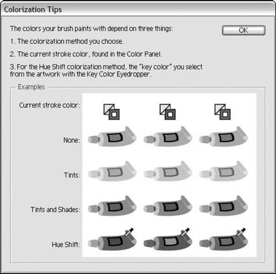
The Tips button in the Art, Scatter, and Pattern Brush dialog boxes displays a dialog box explaining the different colorization options. Figure 4.37 shows the Colorization Tips dialog box, which has four areas of colorization: None, Tints, Tints and Shades, and Hue Shift.
To see how the Colorization options work, first create four copies of a brush. For the first copy, use the default of None. For the next three copies, change the stroke color (you won't see anything happen yet). Double-click the second copy and then choose Tint. Apply the stroke when asked to do so in the dialog box. The color should change at this point. Double-click the third copy and then choose Tints and Shades. Double-click the last copy and then choose Hue Shift. All the copies should look different.
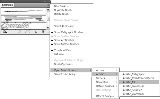
The Brush Library that displays when you choose the Brush panel is the default library. You have additional libraries from which to choose. Adobe has really come up with some cool brushes for your creative pleasures. The other libraries are found under the Window menu, as shown in Figure 4.38.
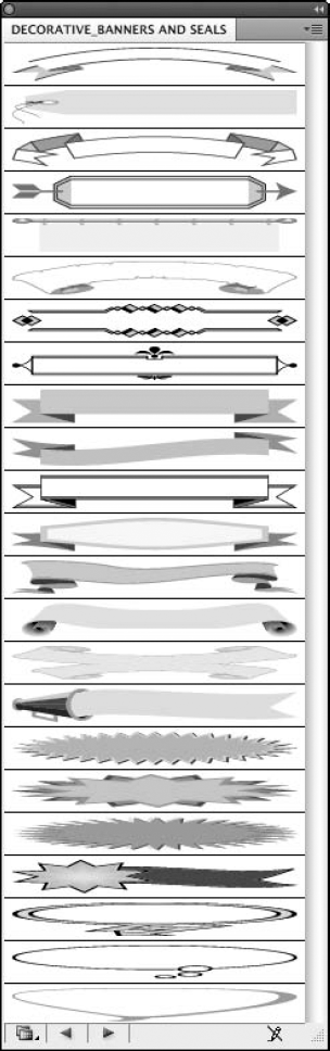
To use a brush from another Brush library, choose the brush you want from the scrolling list. Figure 4.39 shows just one of the many libraries that are included with Illustrator.
Illustrator's drawing tools provide you with many powerful methods of quickly creating artwork. In this chapter, you learned the following important points about using these tools:
Illustrator includes four anchor point types: straight corner points, combination corner points, smooth points, and curved corner points.
Edit curves with the control handles.
Curves are based on the Bézier principle.
Use the Pencil tool to create paths quickly.
Use the Smooth and Path Eraser tools to edit your paths.
Although the Pen tool is the most difficult to learn, it yields the smoothest results.
The Paintbrush tool creates a free-formed stroked path.
A pressure-sensitive tablet can mimic hand-drawn art.
The Line Segment tool can create straight lines. Other tools with the Line Segment tool let you create arcs, grids, polar grids, and spirals.
The Scatter brush repeats objects along a path rotated and sized differently.
The Art brush stretches an object to the length of the path.
The Pattern brush repeats a pattern on a path.
You can create a new brush in the Brushes panel.