Creating rectangles, ellipses, polygons, and stars
Using the Flare tool
Understanding fills and strokes
Designing graphs, charts, flowcharts, and diagrams
Using the Symbol Sprayer tools
Editing and altering symbols
In this chapter, you learn how to create objects, such as rectangles, ellipses, polygons, and stars. In addition, you find out how to create and enhance graphs, add touches of light with the Flare tool, and create really cool repeating effects with the Symbolism tools.
This is actually a very important chapter because it introduces the objects, graphs, and symbols that you will often use in later chapters. Be sure to take the time to understand the concepts that are presented in this chapter so that you have an easier time later.
Drawing the most basic shapes — rectangles, ellipses, polygons, and stars — is precisely what a computer is for. Try drawing a perfect ellipse by hand. Troublesome, isn't it? How about a square that doesn't have ink bubbles or splotches at the corners? A nine-pointed star? Drawing these objects and then coloring them in Illustrator is so easy and so basic that after a few weeks of using Illustrator, you never have to draw a shape by hand again without wincing — and maybe even shuddering.
Illustrator exemplifies the true power of object-oriented drawing programming. No matter what you draw, you can adjust and move each piece of the drawing independently until it's just right. Don't like the sun so high in your background? Pull it down and tuck it in just a bit behind those mountains. Is the tree too small for the house in your illustration? Scale it up a bit. This feature is great not only for artists but also for your pesky client (or boss) who demands that everything be moved except that darned tree.
And after you create the shape, you can move, rotate, scale, and manipulate it in any way you want. Figure 5.1 shows an illustration drawn one way and then modified in a matter of seconds by moving existing elements and adding a few anchor points.

Figure 5.1. A basic square (top) becomes a more interesting shape (bottom) with a few simple modifications.
Remember these general concepts when you draw basic shapes:
Creating common shapes: You can draw common objects (or shapes) in Illustrator, including squares and rectangles, rectangles with rounded corners, circles and ellipses, polygons, and stars. Tools for creating these objects are found as popup tools in the Tools panel under the Rectangle tool. You basically use all these tools in the same manner. So, after you learn how to use the Rectangle tool later in this chapter, you'll know how to use the other tools.
Lines and points that appear when you select an object: After you draw a shape, an outlined closed path appears with blue points indicating the anchor points. The edge of the path has thin blue lines surrounding it. These blue lines indicate that the object is currently selected.
Tip
Note that the closed path appears in black unless you've changed the default fill and line colors. For more on changing the fill or line color, see the section on this topic later in this chapter. Also, the anchor points appear as blue points only if you're in Preview mode, the default viewing mode. To learn more about the view modes in Illustrator, see Chapter 2.
Changing an object's shape: The initial click you make with any of the shape tools is called the origin point. While you drag a shape, the origin point never moves, but the rest of the shape is fluid, changing shape as you drag in different directions and to different distances with your mouse. Dragging horizontally with almost no vertical movement results in a long, flat shape. Dragging vertically with very little horizontal movement creates a shape that's tall and thin. Dragging at a 45° angle (diagonally) results in a regular (in the geometric sense) shape.
Typing exact dimensions in a shape's dialog box: If you click with a tool on the Artboard without dragging it, the shape's dialog box appears. The center of the shape is now where you clicked (normally, the corner of the shape is where you click). Unlike manually drawing (dragging) centered shapes, the dimensions you type are the actual dimensions of the shape. The dimension is not doubled as it is when you drag a centered shape.
Changing units of measure: When you first run Illustrator, all measurements are set to points. Therefore, the values inside the various shape dialog boxes appear in so many points (12 points in a pica). To change the units of measure to something else (such as millimeters or inches) and to see how different units of measure compare, see Chapter 8.
Moving shapes while you draw them: While drawing a shape, you may realize that you want to move it. In Illustrator, you can move any shape by holding the spacebar while depressing your mouse button and then dragging your shape to a new location. When you let up on the spacebar, you can continue to draw your object.
Deleting shapes: Deleting the shape you've drawn is even easier than creating it — simply delete it by pressing Backspace or Delete.
Note
Traditional bitmap paint applications don't have the capability to move sections of a drawing (with the exception of the use of layers in software such as Photoshop and Painter). After you move a section of an image in a bitmap program, a hole appears in the place where the section used to be. And if the new location already has an object, you delete this section of the object, replacing it with the new image.
When you draw a shape, Illustrator starts from the corner, and you have to move your mouse to form your shape. However, if you often place shapes on top of or under other objects, you may need to have an even amount of space between your shape and the object it surrounds. Instead of drawing a shape from a corner, you can draw one from its center. Drawing from the corner forces you to eyeball the space around the object, while drawing from the center of the other object ensures that space surrounding the object is the same.
To draw a shape from its center, hold Alt (Option) and then click and drag. The origin point is now the center of the shape. The farther you drag in one direction, the farther the edges of the shape go out in the opposite direction. Drawing from the center of a shape lets you draw something twice as big as the same shape drawn from a corner. As long as you press Alt (Option), the shape continues drawing from its center. If you release Alt (Option) before you release the mouse button, the origin of the shape changes back to a corner. You can press and release Alt (Option) at any time while drawing, toggling back and forth between drawing from a corner and drawing from the center. You can switch back and forth when drawing rectangles and ellipses only.
You can force Illustrator to create symmetric shapes by holding Shift as you draw a shape. For example, when you press Shift while drawing a rectangle, the rectangle constrains to a square. Likewise, you can draw a perfect circle by holding Shift as you draw an ellipse. You can do this for all the shape tools as well as the Line and Pencil tools.
You can also use the Rectangle (or Ellipse) dialog box to draw a perfect square (or circle) by typing equal values for the width and height. Simply click without dragging to get the dialog box to appear.
Tip
To draw shapes from their centers and to make them symmetric at the same time, draw the shape while holding both Alt (Option) and Shift. Ensure that both keys are still pressed when you release the mouse button.
Usually, when you draw a shape with a tool, the shape orients itself with the document and the document window. For example, the bottom of a rectangle aligns parallel to the bottom of the document window.
But what if you want to draw shapes that are all angled at 45° on the page? Well, one possibility is to rotate them after you draw them by using the Transform Each command or the Rotate tool. Better yet, you can set up your document so that every new shape automatically appears at an angle.
Note
For more on the Transform Each command and Rotate tool, see Chapter 11.
The angle of a shape depends on the Constrain Angle value. Usually, the Constrain Angle is 0°, where all shapes appear to align evenly with the borders of the document. To change the Constrain Angle, choose Edit (Illustrator)
When you finish drawing these angled shapes, ensure that you change the Constrain Angle setting back to 0° or you create all new shapes at the altered Constrain Angle.
Tip
Constrain Angle affects shapes and other objects created in Illustrator, including type. In addition, dragging objects while pressing Shift constrains them to the current Constrain Angle or to a 45° or 90° variation of it. The Constrain Angle is much easier to see if you turn on Grids by choosing View
The most basic shape you can draw is a rectangle. Although the following steps explain how to draw a simple rectangle, you essentially use these same steps for all the other shape tools in Illustrator.
Click the Rectangle tool. You can do this by clicking it in the Tools panel or by pressing the M on the keyboard. You find the Rectangle tool in the second column of the Tools panel on the fourth row from the top.
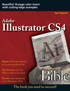
Click your mouse on the Artboard and then hold the mouse button. This sets the origin point of the rectangle. If you press Alt (Option) while you hold the mouse button, you create the rectangle from the center instead of the corner.
Drag your mouse diagonally to the size you desire. You can draw rectangles from any corner by clicking and dragging in the direction opposite from where you want that corner to be. For example, to draw a rectangle from the lower-right corner, click and drag up and to the left.
Release the mouse button. Illustrator creates a rectangle, as shown in Figure 5.2. The farther the distance from the initial click to the point where you release the mouse button, the larger the rectangle. As long as you have the Rectangle tool selected, dragging with it in the document window produces a new rectangle.
Note
Press the tilde (~) key while drawing with the Rectangle tool (as well as all the other shape tools) for a mind-bending, super-insta-duplication effect. Just be prepared to press Ctrl+Z (
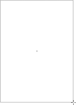
If you want to create a rectangle with exact dimensions, all you have to do is open the Rectangle dialog box and type the dimensions. The steps that follow also apply to the other basic shape tools in Illustrator. To draw a rectangle of an exact size, follow these steps:
Click and release the Rectangle tool where you want to place the upper-left corner.
The Rectangle dialog box, as shown in Figure 5.3, opens.
Type the width and height. When the Rectangle dialog box opens, values are usually already inside the text fields. These numbers correspond to the size of the rectangle you last drew. To create another rectangle of the same size, just click OK (or press Enter or Return). To make the rectangle a different size, replace the values with your own measurements. If a text field is highlighted, typing replaces the text in the text field and deletes what had been highlighted.
Tip
To highlight the next text field in a dialog box, press Tab. You can also highlight the preceding text field in a dialog box by pressing Shift+Tab. If you want to highlight any text field instantly, double-click the value or click the label next to that value.
Click OK. Illustrator draws the rectangle using precisely the size that you specified. To get out of the Rectangle dialog box without drawing a rectangle, click Cancel or just press Esc (

Rectangles whose sizes are specified in the Rectangle dialog box are always drawn from the upper-left corner. The largest rectangle you can draw is about 19 feet by 19 feet. It's a wonder you can get anything done at all with these limitations!
Sometimes, straight corners just aren't good enough. That's when it's time to create a rectangle with rounded corners. Why? Maybe you want your rectangles to look less computery. A tiny bit of corner rounding (2 or 3 points) may be just what you need.
Before getting into how to actually draw rounded rectangles, it helps to understand how Illustrator sets the roundness of your corners. It performs this feat in one of three ways:
Using the most recently drawn rounded-corner rectangle: Illustrator sets the corner radius value using the dimensions of the most recently drawn rounded-corner rectangle and then places this value in the General Preferences dialog box. In other words, after you draw a rectangle using the Rounded Rectangle tool, Illustrator saves those dimensions for the next time that you draw a rounded rectangle.
Using the General Preferences dialog box: What if you don't want to use the radius of the last rounded rectangle? You use the value in the General Preferences dialog box, of course. To do so, choose Edit (Illustrator)

Using the Rounded Rectangle dialog box: Changing the value in the Corner Radius text field in the Rounded Rectangle dialog box not only changes the current rounded rectangle's corner radius value but also changes the radius in the General Preferences dialog box. Illustrator uses this corner radius for all subsequently drawn rounded rectangles until you change the radius value again.
Now that you understand how Illustrator works when you draw rounded rectangles, the next step is to learn how to draw one. You can create a rounded rectangle in one of two ways: You can accept the current radius and draw or you can change the current radius and draw.
To draw a rounded rectangle with the current radius, use the Rounded Rectangle tool:
Click the Rounded Rectangle tool. You do this by clicking and holding the Rectangle tool in the Tools panel until a popup menu opens. Next, drag your mouse to the right to choose the Rounded Rectangle tool.
Click and drag with the Rounded Rectangle tool as if you're drawing a standard rectangle. The only difference is that this rectangle has rounded corners. The point at which you clicked is where the corner would be — if there were a corner. Of course, with rounded corners, there's no real corner, so the computer uses an imaginary point called the origin point as its on-screen corner reference.
Alternatively, you can specify a corner radius value in the Rounded Rectangle dialog box by following these steps:
Click the Rounded Rectangle tool as before.
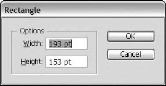
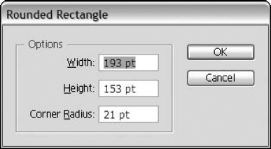
Click the Artboard with the Rounded Rectangle tool. The Rounded Rectangle dialog box, as shown in Figure 5.4, opens.
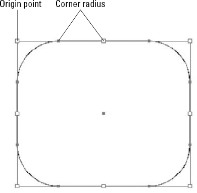
Specify a value in the Corner Radius text field. The third text field is for the size of the corner radius. This option makes the corners of the rectangle curved, although leaving the setting at a value of 0 keeps the corners straight. The corner radius in Illustrator is the length from that imaginary corner (the origin point) to where the curve begins, as shown in Figure 5.5. The larger the value you type in the Corner Radius text field of the Rectangle dialog box, the farther the rectangle starts from the imaginary corner and the bigger the curve. For example, if you set the corner radius at 1 inch, the edge of the rectangle starts curving 1 inch from where a real corner would normally appear.
Click OK. Illustrator applies your changes.
Click and drag with this tool as if you're drawing a standard rectangle. Your rounded rectangle appears.
Tip
If the corner radius is more than half the magnitude of either the length or width of the rectangle, the rectangle may appear to have perfectly round ends on at least two sides. If the corner radius is more than half the magnitude of both the length or width of the rectangle, then the rectangle becomes an ellipse!
Tip
Need to draw a rounded rectangle from the center or create a rounded square? Use the Rounded Rectangle tool and then follow the instructions presented earlier in this chapter.
How the Corner Radius Really Works
For all you geometry buffs, the whole corner radius business works this way: The width of the Bounding Box of any circle is called the diameter of that circle; half the diameter is the radius of the circle, as indicated in the following figure.
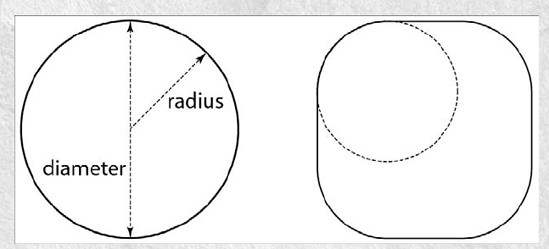
The diameter and radius of a circle
If you create a circle with a radius of 1 inch, the circle actually has a diameter of 2 inches. Put this 2-inch circle into the corner of the rectangle, as in the preceding figure, and the curve of the circle matches the curve of the rounded rectangle that has a corner radius of 1 inch.
To realistically determine the way a rounded corner will look, use the method that measures the distance from the imaginary corner to the place where the curve starts.
If you have an existing rectangle with straight corners and you want to make the corners round, neither of the methods presented earlier in this chapter is going to help you. Instead, you must choose Effect
Furthermore, this command can't change corners that you've rounded with either the Rounded Rectangle tool or through previous use of the Round Corners dialog box.
What if you want your corners to round inward instead of out? Initially, it would seem that you're out of luck because Illustrator doesn't provide any way for you to type a negative value for a corner radius. However, you can manipulate the corners manually. The following steps explain how to create a reverse rounded-corner rectangle:
Draw a rounded rectangle with the dimensions that you desire. For more on drawing rounded rectangles, see the section on this topic earlier in this chapter.
Select the leftmost point on the top of the rounded rectangle by dragging the Direct Selection tool (the hollow arrow) over it. One control handle appears, sticking out to the left.
Click and drag the control handle down below the anchor point while pressing Shift and then release the mouse button. Holding Shift ensures that the control handle line is perfectly vertical.
Select the topmost point on the left edge by dragging the Direct Selection tool over it. A control handle appears, sticking straight up out of this anchor point.
Click and drag the control handle to the right while pressing Shift and then release the mouse button.
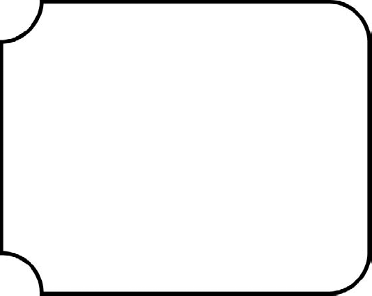
Repeat these steps for each of the corners. After you get the hang of it, the points start flying into position almost by themselves. Figure 5.6 shows an example of a rectangle with backward-rounded corners on the left side.
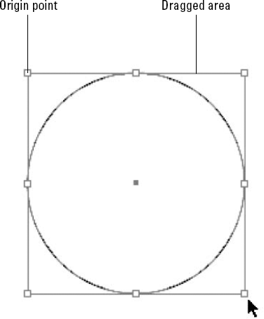
Drawing an ellipse is harder than drawing a rectangle because the point of origin is outside the ellipse. With a rectangle, the point of origin corresponds to a corner of the rectangle, which also happens to be an anchor point. The ellipse is completely within the rectangle. Figure 5.7 shows that the top edge of the ellipse is at the midpoint of the dragged rectangle.
Tip
Press Ctrl (
Follow these steps (similar to those for drawing a rectangle) to create an ellipse:
Click the Rectangle tool and then choose the Ellipse tool. The Ellipse tool is housed with the Rectangle tool.
Click and drag diagonally. The outline of an ellipse forms.
Release the mouse button. The ellipse appears on-screen. Ellipses, like rectangles, have four anchor points, but the anchor points on an ellipse are at the top, bottom, left, and right.
Tip
Draw a circle by pressing Shift while drawing your ellipse.
Although creating more and more ellipses, rectangles, and rounded rectangles is loads of fun, sooner or later, you're going to get bored. I dare say that you can create more interesting shapes automatically by using some of the additional shape tools that come with Illustrator. Most of these tools are located in the Rectangle tool slot in the Tools panel, as shown in Figure 5.8.

Figure 5.8. The Rectangle tool slot, which appears here as a tearaway, and the tools housed with it allow you to draw many shapes.
To create a polygon, you first want to specify the number of sides for your polygon and then you can draw it following these steps:
Click the Polygon tool. This tool is located below the Ellipse tool in the Rectangle tool slot.
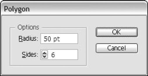
Click the Artboard with the Polygon tool. You want to do this before you draw the polygon. Clicking the Artboard displays the Polygon dialog box, as shown in Figure 5.9.
Specify values for the polygon. The Polygon dialog box has the following options, both of which you must specify:
Radius: This is the distance from the center of the polygon to one of the vertices of the polygon. For even-sided shapes (4, 6, 8, 10, and so on, sides), the radius is half the width of the object, from one corner to the opposite corner. For odd-sided shapes, the radius is the distance from the center of the polygon to any of the vertices. Its diameter is twice that value.
Sides: This is the number of sides that you want for the polygon.
Click OK.
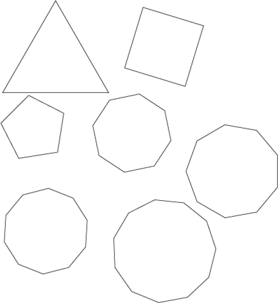
While drawing a polygon, you can change the number of sides on the fly without reopening the Polygon dialog box. To increase or decrease the number of sides, press the up or down arrow as you drag. Figure 5.10 shows different polygons drawn with the Polygon tool.
All polygons you create with the Polygon tool are regular polygons, meaning that they have sides of equal length. For this reason, every four-sided object that you create is a square and every six-sided object is a perfect hexagon. You may find the square capabilities of the Polygon tool useful; it can save you a step when you want to draw a square at an angle. You can't do this with the Rectangle tool unless you change the Constrain Angle in the General Preferences prior to drawing the square or use the Rotate tool on the square after you draw it.
Note
For more on the Rotate tool, see Chapter 11.
If you press Shift while dragging your mouse, the polygon you create is upright. It aligns to the current Constrain Angle (usually 0°). Therefore, if you create a triangle and you press Shift, the triangle has one side that's perfectly horizontal (the bottom) unless you have a different Constrain Angle, in which case one edge of the triangle aligns to that angle.
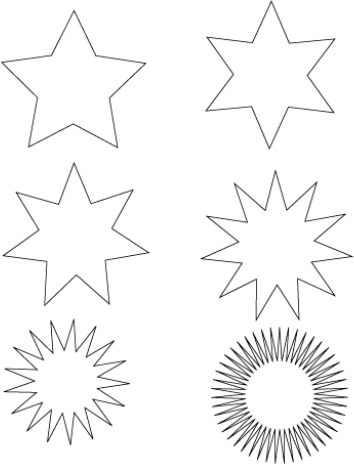
To create stars, click the Star tool, which is in the Rectangle tool slot, and then drag in the document. As you drag, a star is created. Several stars are shown in Figure 5.11.
Stars have several of the same controls as polygons when you're drawing them: Pressing Shift aligns the star to the Constrain Angle, the spacebar moves the star around, and the tilde (~) key makes lots more stars. The up and down arrows work a bit differently; instead of adding and removing edges, they add and remove entire points. So, in a way, they're actually adding two edges. Stars must have an even number of sides or they're not really stars; they're the pointy lumps you doodled during your poly-sci classes as a sophomore.
The Star tool adds two additional keys for other functions: Pressing Alt (Option) positions the inner points relative to the outer points to produce a star with a corresponding side lying along the same line. Illustrator refers to them as fixed stars. And in case it's keeping you up at night, Alt (Option) has no effect on stars with three or four points.
Perhaps the most versatile function associated with the Star tool (and the Rectangle, Ellipse, Polygon, Spiral, and Ellipse tools) is what happens when using the tilde (~) key. When you press the tilde key and draw, several shapes appear rapidly. As Figure 5.12 shows, this technique can create all sorts of interesting designs.
Stars can come in all shapes, not just the fixed and standard shapes. You create these shapes by pressing Ctrl (
You can also specifically design a star by clicking with the Star tool to display the Star dialog box, as shown in Figure 5.13, where you can type the number of points and both the first and second radius of the points.
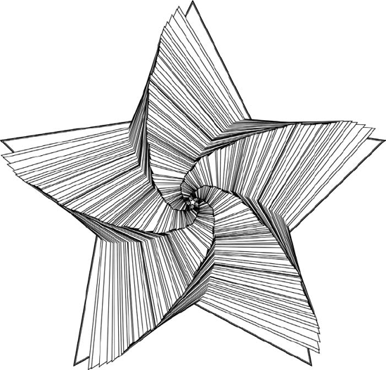
Figure 5.12. Press the tilde (~) key as you drag with most drawing tools to create some interesting designs.
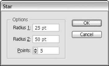
Figure 5.13. The Star dialog box lets you specify both inner and outer radius values as well as the number of points.
Turning Regular Stars into Something Spectacular
Of course, all the stars you create with the Star tool consist of regular-looking stars. However, using the steps that follow, you can turn an ordinary star into something spectacular. For example, you can use these stars to jazz up text for a more eye-catching look for an advertisement. Another good idea for using spectacular stars is for seals or official-looking approvals. For a more dramatic-looking starburst, follow these steps:
Create a star with about 30 points. Make it look something like the one in the first figure.
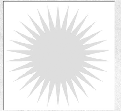
Start with a simple star.
Choose Effect
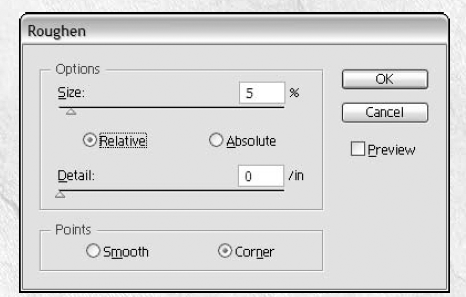
Add an effect.
In the Roughen dialog box, change the Size to 5% and the Detail to 0. Keeping the Detail at 0 won't let Roughen add any anchor points. Applying the Roughen effect makes some star points longer than others randomly, using 5% as the amount of change for any one point.
Click the Corner radio button in the Points section (so you don't have curves on your star-burst) and then click OK. You can also click the Preview check box; each time you click and deselect it, a new preview results, regenerating the randomness each time. Clicking OK uses the Roughen preview you see on-screen, as shown in the next figure.
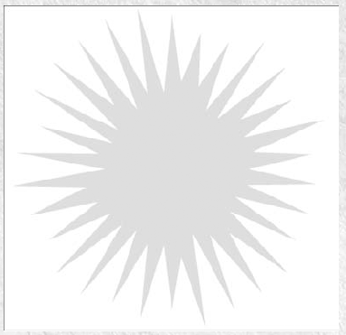
Apply your changes.
Add any extras, such as a drop shadow, text, etc. My end result is shown in the final figure.

And there you have it! A work of art!
The Flare tool is more than a welcome complement to Illustrator's amazing tools. Housed with the Rectangle tool, the Flare tool is used to create a flare. Seems simple, but what exactly is a flare? A flare is a highlight or reflection from a light source. Figure 5.14 shows an Illustrator flare used in a movie poster.
With most tools, you have options. To access the Flare tool options, double-click the Flare tool to display the Flare Tool Options dialog box, as shown in Figure 5.15.
In the Flare Tool Options dialog box, you can choose from many options, including these:
Center: Sets the diameter, opacity, and brightness of the center of a flare.
Halo: Sets the percentage of a halo's fade outward and its fuzziness. A low fuzziness results in a clean, crisp halo.
Rays: Sets the number of rays, the longest ray length, and the fuzziness of rays. If you don't want rays, type 0 for the number of rays.
Rings: Sets the distance of the path between a halo's center and the center of the farthest ring, the number of rings, the size of the largest ring, and the ring direction.
After you create a flare, you can always edit it by selecting the flare first and then clicking and dragging with the Flare tool to change the direction or length. If you expand the object, the flare changes to a blended object (one with smooth transitions between the colors). That way, you can change the number of blend steps or colors if necessary.
The Flare tool is perfect for making a nighttime sky of stars. You can use any backdrop with your graphic illustration. For variation, drag small, medium, and large flares for depth to the stars. Dragging a small amount outward creates a small flare; a little larger drag creates a medium flare; a big drag outward creates a large flare.
The best use of flares is to add a highlight to an object. For example, you can drag out a flare on the corner of an object to simulate light reflecting off it. You simply click and drag to place the center of a flare, click to set the size of the center and the halo, and then rotate the ray angle.
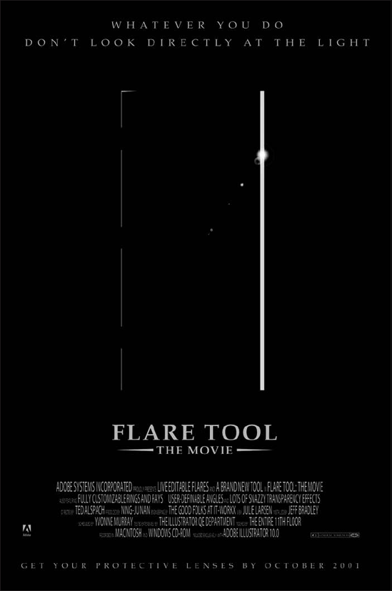
Figure 5.14. The Flare tool creates flared light from a bright source, as shown in this movie poster.
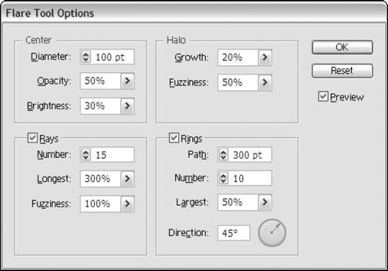
Figure 5.15. The Flare Tool Options dialog box allows you to choose the settings for drawing flares.
You can use keyboard commands while drawing to modify a flare:
Shift: Constrains the rays of a flare to 45° increments.
Up arrow: Adds rings. Each time you press the up arrow as you're drawing a flare, you add rings. Keep pressing for lots of rings.
Down arrow: Deletes rings. Each time you press the down arrow as you're drawing a flare, it takes away rings.
Ctrl (
After you draw a flare, it's not set in stone. Maybe you don't like how far the flare is going out or maybe you want to see additional rings. You can always go back and edit the flare to remove rings, change the distance, etc. You have two ways to edit a flare:
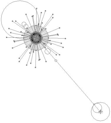
Using the Flare tool: Select the flare that you want to edit. Using the Flare tool, drag the endpoint to a new length or in a new direction. An example of this is shown in Figure 5.16.
Using the Flare Tool Options dialog box: Select the flare that you want to edit. Double-click the Flare tool to open the Flare Tool Options dialog box. Change the values in the dialog box to edit the flare. Refer to Figure 5.15 to see the Flare Tool Options dialog box.
One of the most powerful features of Illustrator is its ability to color objects. In Illustrator, you can color both the fill and the stroke of the paths that you create. The fill is the internal portion of a shape, while the stroke is the edge of a shape.
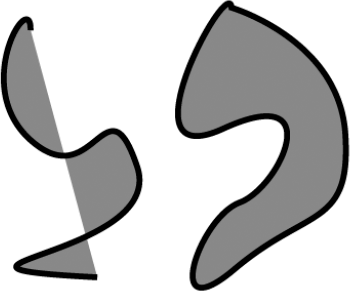
The fill of an object is the color inside the shape. If a path is closed (a condition where there are no endpoints and the object's path is connected from end to end), the fill exists only on the inside of the path. If the path is open or has two endpoints, the fill exists between an imaginary line drawn from endpoint to endpoint and the path itself. Fills in open paths can provide some very interesting results when the path crosses itself or the imaginary line crosses the path. Figure 5.17 shows examples of fills in open and closed paths. Fills don't appear in Outline mode, only in Preview mode.
Note
For more on fills, see Chapter 10. For more on Preview and Outline modes, see Chapter 2.
Besides black and white, the fill color options include the following:
Process Colors: A process color is made up of four inks: cyan, magenta, yellow, and black, also known as CMYK. Most commercial printers use these four colors to create your illustrations.
Spot Colors: Spot color is created using inks that have been premixed. A spot color uses its own printing plate rather than the standard CMYK plates.
Patterns: A pattern consists of created artwork that's repeated or laid out like tiles to fill a space.
Gradients: A gradient blends two or more colors together for a smooth transition between colors.
Gradient Meshes: A gradient mesh changes the object by adding blended lines to accommodate the changes in colors.
None: This is where the fill is transparent. This option lets you see behind a path to what is underneath it when the stroke of an object is the visible part.
A stroke is defined as the outline or the path of an object. Any object you draw can have a stroke applied to it, including shapes, lines, paths, and even text. The stroke of an object is made up of three parts: color, weight, and attributes. Strokes appear where there are paths or around the edges of type. Like fills, any one path or object can have only one type of stroke on it; the color, weight, and style of the stroke are consistent throughout the length of the path or the entire text object. Individual characters in a text object can have different strokes only if you select them with the Type tool after you apply the stroke attributes.
Note
For more on how to apply strokes to text, see Chapter 9.
Besides black and white, the stroke color options are the same as those for fills, except that you can't apply gradients and gradient meshes to a stroke. To apply a stroke color, simply choose the stroke color at the bottom of the Tools panel or press X and then choose the color to use from the Color panel or from the Swatches panel.
The weight of a stroke is how thick it is. On a path, Illustrator centers the stroke on that path, with half the thickness of the stroke on one side of the path and half the thickness on the other side of the path. So a 1-point stroke has ½ point on each side of the path.
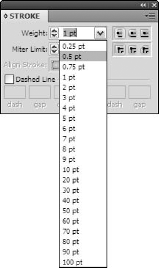
You set stroke weight in the Stroke panel's Weight menu or by typing a value in the Weight text field. Figure 5.18 shows the Stroke panel. You can also use the up and down arrows on the left of the Weight text box to incrementally change the stroke weight.
Tip
Use mathematical operations in the Stroke panel! You can mathematically change the current stroke weight by adding, subtracting, multiplying, or dividing by any value. Just place the appropriate symbol (+ for add, − for subtract, * for multiply, and / for divide) after the current value and then the number by which you want to perform the operation. Use this when you're asked to increase the stroke weight by, say, 2 times the current value.
Strokes have upper and lower limits. You can never create strokes wider than 1000 points. A stroke with a weight of 0.001 can exist in Illustrator, although the recommendation is that you not choose such a value. Instead, set the stroke to 0. Because a stroke of 0.001 changes to match the output device (it appears 1 pixel thick or as a 1-point stroke on-screen), the potential changes in thickness can drastically change the way an image looks. Be very careful if you choose to venture into this area of Illustrator.
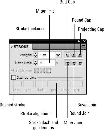
The attributes of a stroke consist of several parts, including the cap style, join style, miter limit, and dash pattern. Figure 5.19 shows the Stroke panel where you choose these attributes.
The stroke attributes include the following options:
Cap style: The way the ends of a stroke look. This style can be butt cap, rounded cap, or projected cap. Caps apply only to endpoints on open paths. You can choose a cap style for a closed path (with no endpoints), but nothing happens; if the path is cut into an open path, that cap style goes into effect.
Butt Cap: Chops the stroke off perpendicularly at the end of the path
Round Cap: Results in smooth, rounded ends that resemble a half-circle. These caps protrude from the endpoint one-half the stroke weight.
Projecting Cap: Projects from the endpoint one-half the stroke weight and appear perpendicular to the direction of the path at its endpoint
Join style: The join style is the manner in which the corner points on paths appear when you stroke them. You can apply one of three join styles to paths:
Miter Join: Causes the outer edges of the stroke to meet at a point. This join type is the only one affected by the miter limit.
Round Join: Rounds off the outside edge of corners
Bevel Join: Is cropped off before the angle can reach a corner
Joins affect only corner points, including straight corner points, curved corner points, and combination corner points. In all cases, join types affect only outside corners. Inside corners always appear mitered.
Miter Limit: The Miter Limit option controls how far a corner can extend past the edge of the path. This is important for tight corners of paths with large weights because the place where the outside edges meet in a corner can be really far away from the original edges of the paths. The number in the Miter Limit controls how many times the width of the stroke the miter can extend beyond the point. The default is 4, which is good for the majority of applications.
Align Stroke: Use this option to control how the stroke aligns with the path. It can be centered over the path, inside the path, or outside the path.
Dashed Line: Usually, the dash pattern for a stroke is solid, but you can create various dash patterns for different effects. The bottom of the Stroke panel controls if and how dashed strokes should appear. Clicking the Dashed Line check box allows you to type different values for up to three dash and gap lengths.
Many times, paths in Illustrator require both fills and strokes. When you give both a fill and a stroke to a single path, the stroke knocks out the fill at the edges of the path by one-half the weight of the stroke. Figure 5.20 demonstrates this by using a dashed stroke to make the point a little more obvious.
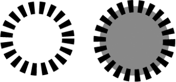
Figure 5.20. A stroke knocks out a fill by one-half the weight of the stroke, as shown on the right circle.
Tip
If knocking out the fill of a path hides part of the pattern that you want to be seen, you can correct this problem by copying the path and pasting it in front, removing the frontmost path's stroke. Be warned, though, that the filled path, on top of the stroked path, knocks out the inner half of the stroke.
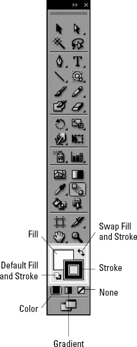
The Tools panel contains fill and stroke icons, which are located in the Paint Style section of the Tools panel and shown in Figure 5.21.
By default, the fill is set to White and the stroke is set to 1-point Black.
But you can reset to the default fill and stroke by clicking the Default Fill and Stroke icon in the lower-left corner of the Paint Style section.
You can also quickly swap between the colors in the Fill and Stroke icons by clicking the Swap Fill and Stroke icon located in the upper right of the Paint Style section.
When you first start Illustrator, the Fill icon is in front of the Stroke icon. This means that any changes made in the Color or Swatches panels affect the fill. When the Fill icon is in front of the Stroke icon, the fill is said to be in focus. You can change the focus to the stroke by clicking the Stroke icon. When the focus is on the stroke, changes made in the Color or Swatches panels affect the stroke, not the fill.
Tip
You can quickly reset the fill and stroke colors to their defaults by pressing D. You can quickly change the focus from the Stroke icon to the Fill icon by pressing Shift+X.
The Fill and Stroke icons change in appearance to match the current fill and stroke. For example, if you have a purple fill and an orange stroke, the Fill icon is purple and the Stroke icon is orange, and you obviously slept through the color-coordination lectures in your design classes. The Fill icon displays a gradient or pattern if that's the current fill.
You use the three icons at the bottom of the Paint Style section to determine the type of fill or stroke:
Color: You use this icon when you want to have a solid color or pattern for the fill or stroke. Press the comma (,) key to quickly activate the Color icon.
Gradient: Use this icon when the fill contains a gradient. You can't color a stroke with gradients; clicking this icon when the Stroke icon is in focus changes the fill to gradient and also changes the focus to fill. Press the period (.) key to quickly activate the Gradient icon.
None: This creates an empty fill or no stroke. Fills of None are entirely transparent.
Strokes of None aren't colored and have no stroke weight. Press the forward slash (/) key to quickly activate the None icon.
Oddly enough, you don't need to use the Color and Gradient icons to determine the type of fill when switching between color and gradient; you can simply click the appropriate swatch in the Swatches panel to change the fill type. No swatch for None is available; to change the fill or stroke to None, you must either click the None icon or press the forward slash (/) key. You can quickly combine pressing X and / to change the focus and apply None to the stroke or fill.
Graphs are most useful when they show numerical information that normally takes several paragraphs to explain or that you can't easily express in words. You can easily overlook a significant difference between two numbers until you use a graph to represent them. The Graphs feature is one of the most underused features in Illustrator. Most people use programs such as Microsoft Excel to design their graphs. You just wouldn't think Illustrator could do graphs with accuracy, but it can — and with more than just the boring graph visuals.
An exciting aspect about graphs in Illustrator is their fluidity. Not only can you create graphs easily, but you can also change them easily. In addition, if the data that you used to create a graph changes, you can type the new data and have it instantaneously appear in the graph.
All the graph tools work in a manner similar to that of the shape creation tools. For example, when you choose the Graph tool, you can click and drag to set the size of the graph or you can display the tool's dialog box (in this case, the Graph Size dialog box) by clicking the Artboard without dragging to type the size information.
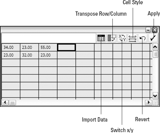
The Graph Data box, as shown in Figure 5.22, looks like a simple spreadsheet with rows and columns. Using this box, you can type data to graph. After you type the data, click Apply (which looks like a check mark), and Illustrator updates your graph.
Warning
Ensure that the graph is never ungrouped (a graph always has all its elements grouped together, meaning that you can select them with the Selection tool as a whole rather than individual pieces), at least not until you finish making all graph data and graph style changes. If you ungroup the graph, you can't use any of the graph options to change the ex-graph because Illustrator views it as just a set of paths and text.
Note
For more on grouping and ungrouping, see Chapter 8.
You can import graph data in tab-delimited text files, such as those exported by Microsoft Excel. Tab-delimited files are text and numbers that are separated by tabs and newlines. To import data from another file, click Import, the leftmost icon at the top of the Graph Data box, and then choose the text file containing the information you want to graph.
Warning
The text file that you import can't contain any punctuation except for decimal points. If you've formatted the text file with thousands separators (with commas), the numbers will not import correctly.
Because Illustrator is not really a graphing or spreadsheet program, many of the usual controls for arranging data in such programs aren't available, including inserting rows and columns and creating formulas.
The Cut, Copy, and Paste functions work within the Graph Data box, so you can move and duplicate information on a very basic level.
One very useful feature in the Graph Data box is the Transpose row/column button. This function switches the x- and y-axes of the data, thus swapping the row and column layout of everything that you've typed.
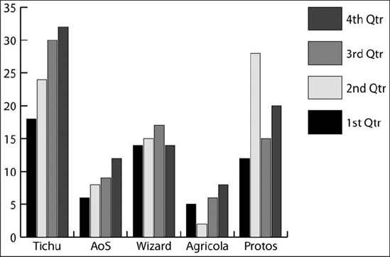
Use the following steps to create a basic graph. The type of graph in this example is a grouped column graph, which you commonly use to compare quantities over time or between different categories:
Click the Graph tool. The tool is located midway down in the Tools panel and looks like a bar graph.
Click and drag to form a rectangular area. You do this as you would when using the Rectangle tool. The size of the rectangle that you create becomes the size of the graph.
Release the mouse button. As soon as you do so, an untitled floating window appears, containing a simple worksheet. This floating window is the Graph Data box (refer to Figure 5.22).
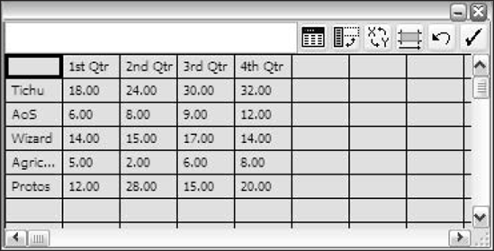
Type your data into the Graph Data box. Information that you type in the worksheet becomes formatted in graph form. The top row in the worksheet area should contain the labels for comparison within the same set. The items in the top row appear as legends outside the graph area. In the leftmost column, you can type labels that appear at the bottom of the grouped column graph as categories. In the remaining cells, type the pertinent information, as shown in Figure 5.23.
Close the window. This signals Illustrator to use the data that you typed in the graph. The graph appears, and it should look something like the one in Figure 5.24.
Change your Graph styles. After you create the graph, you can change the Graph styles to see which graph shows the information the best.
Tip
To have the labels on the legends to read numbers only, you must place quotation marks (" ") around the numbers. If you don't use quotation marks, Illustrator considers the numbers as data, not labels.
You can change the numbers and the text in the Graph Data box at any time by selecting the graph and then choosing Object
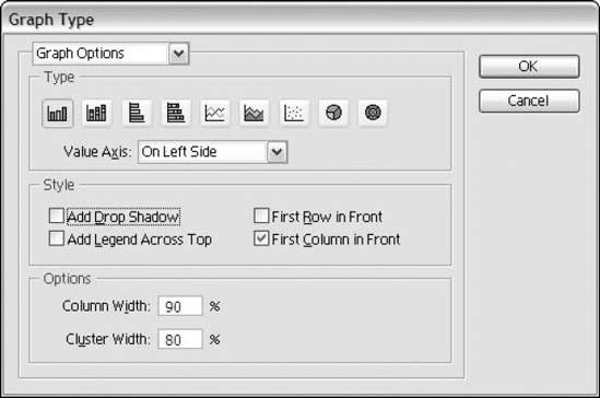
When a graph is selected, you can choose Object
The Graph Type dialog box includes several options for controlling the look of the graph, including the following:
Type: Separate icon buttons are available for each of the graph types: Column, Stacked Column, Bar, Stacked Bar, Line, Area, Scatter, Pie, and Radar.
Value Axis: The choices — On Left Side, On Right Side, On Both Sides — display the vertical values on the left side (the default), the right side, or both sides.
Style: You can choose from these options to add a drop shadow or add a legend across the top of the graph. You can also opt to place the first row in front or the first column in front (for when the columns or rows stack closely together).
Options: These settings are specific to the graph you select. The default graph (grouped column graph) has options to set the column and cluster width in percentage. Each type of graph has its own customization options.
Tip
To make visually striking graphs, use a combination of graph types. Simply use the Group Selection tool to select all the objects that are one legend type, choose Object
In the Graph Options popup menu in the Graph Type dialog box, you can find other options, such as Value Axis and Category Axis. These are the Value Axis and Category Axis options:
Tick Values: This Value Axis option sets the minimum, maximum, and divisions and includes a check box to override calculated values.
Tick Marks: This Value Axis option sets the length and how many ticks are drawn per division.
Add Labels: This Value Axis option sets a prefix and/or a suffix for labels.
Tick Marks: This Category Axis option sets the length and how many are drawn per division and includes a check box to draw tick marks between labels.
You can choose from nine types of graphs in Illustrator. Each type gives a specific kind of information to the reader. Certain graphs are better for comparisons, others for growth, etc. The following sections describe the graphs, explain how to create them, and tell how you can use them.
You primarily use grouped-column graphs to show how something changes over time. Often, they're referred to as bar graphs because the columns that make up the graphs resemble bars.
The real strength of a grouped-column graph is that it provides for the direct comparison of different types of statistics in the same graph.
Column width and cluster width are two customizable options for grouped-column graphs and stacked-column graphs. Column width refers to the width of individual columns, with 100% being wide enough to abut other columns in the cluster. Cluster width refers to how much of the available cluster space is taken up by the columns in the cluster. At 80% (the default), 20% of the available space is empty, leaving room between clusters.
You can widen columns and clusters to 1000% of their size and condense them to 1% of the width of the original column or cluster.
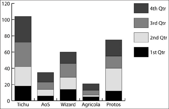
Stacked-column graphs are good graphs for presenting the total of a category and the contributing portions of each category, as shown in Figure 5.26.
This graph shows the same amount of information as the grouped-column graph, but the information is organized differently. The stacked-column graph is designed to display the total of all the legends, and the grouped-column graph is designed to aid comparison of all individual legends in each category.
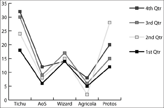
Line graphs (also known as line charts) show trends over time. They're especially useful for determining progress and identifying radical changes, as shown in Figure 5.27.
The Line graph of the Graph Type dialog box (Object
Mark Data Points: This forces data points to appear as squares. If this box is not clicked, the data points are visible only as direction changes in lines between the data points.
Connect Data Points: If you click this check box, Illustrator draws lines between each pair of data points.
Draw Filled Lines (and the corresponding text box for line width): This creates a line filled with the data point legend color and outlined with black.
Edge-to-Edge Lines: This stretches the lines out to the left and right edges of the graph. Although the result is technically incorrect, you can achieve better visual impact by using this feature, and depending on the type of graph you make, visual impact might be more important than getting it right.
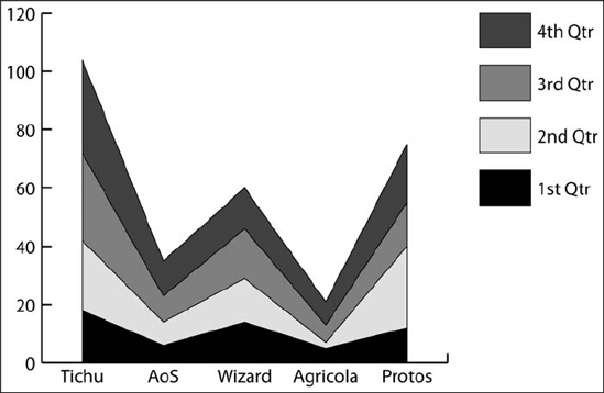
On first glance, area graphs may appear to be just like filled line graphs. Like line graphs, area graphs show data points that are connected, but area graphs, such as the one shown in Figure 5.28, stack data on top of each other to show the total area of the legend subject in the graph. In the Area Graphs dialog box, you can add style to the graph by choosing from these options: Add Drop Shadow, Add Legend Across Top, First Row in Front, and First Column in Front.
Pie graphs are great for comparing percentages of the portions of a whole, as shown in Figure 5.29. The higher the percentage for a certain activity, the larger its wedge. Some of the options for pie graphs are Add Drop Shadow, Add Legend Across Top, First Row in Front, First Column in Front, Legend, Sort, and Position.
When you create pie graphs, you can remove the individual wedges from the central pie with the Group Selection tool to achieve an exploding pie effect.
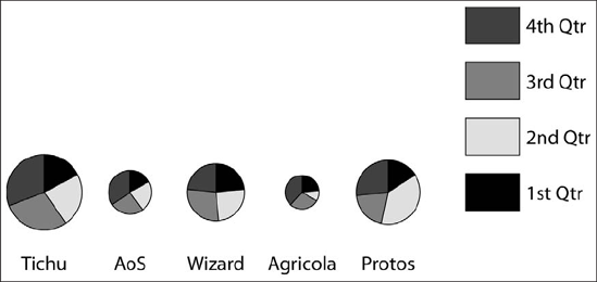
The Legends in Wedges option is the only option in the Graph Type dialog box that's specifically for pie graphs. If you choose this option, the name of each wedge centers within that wedge. Illustrator doesn't do a very good job of placing the legend names, many times overlapping neighboring names. In addition, the letters in the legend names are black, which can make reading some of the names difficult or impossible. Of course, you can always just add legends manually to any graph after the fact using Illustrator's Type tool, but then if the values change (and thus the graph), the graph has the wrong values displayed until you manually change them.
Scatter graphs, which are primarily used for scientific charting purposes, are quite different from all the other types of graphs. Each data point is given a location according to its x-y coordinates instead of by category and label. The points are connected, as are the points in line graphs, but the line created by the data point locations can cross itself and doesn't go in any specific direction. Scatter graphs have the same customization options as line graphs.
A radar (or web) graph compares values set at a certain point. This type of graph is viewed as a circle graph. Categories are spread around the circle, and the data with higher values extend farther from the center.
Illustrator can create a chart for a company's organization. Using the Rectangle tool and some effects, you can make a clean organization chart.
To create an organization chart, whether it's for a business or simply a family tree, follow these steps:
Click the Rectangle tool to draw a rectangle. See the section on drawing rectangles for more on using this tool.
Type a name inside the rectangle. For more on typing text in graphics, see Chapter 9.
Make copies of your rectangle. Press Alt (Option) while dragging with the Selection tool to make copies of the first rectangle. Create as many rectangles as you need and then edit the names with the Text tool.
Figure 5.30 shows an organization chart created using Illustrator.

Figure 5.30. You can use Illustrator to create an organization chart that clearly defines your position.
You can use the same principle for the organizational chart to create a sitemap for a Web site. The main difference is that you organize the sitemap from left to right rather than top to bottom as in an organizational chart. The point is to show the smoothest way that information flows.
With the addition of the Symbol tools in Illustrator 10, small children can now, with ease, make a sensible drawing using the Symbol Sprayer tool. Adults and professionals alike can create amazing designs with very little effort. Illustrator has included a bunch of symbols to use with the Symbol Sprayer tool. If you want to, create your own and then add it to the Symbols panel.
To start using the Symbol Sprayer tool, follow these steps:
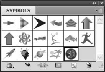
Choose a symbol from the Symbols panel. Figure 5.31 shows the Symbols panel, which you access by choosing Window
Click the Symbol Sprayer tool. This tool is located midway down the left column of the Tools panel next to the Graph tool. It has an icon that looks like a spray can.
Start spraying away. The longer you hold the mouse button down, the more symbols are sprayed in that area. Figure 5.32 shows a bunch of butterflies sprayed on a page.
To change the size of the sprayer or related options, double-click the Symbol Sprayer tool to access the Symbolism Tools Options dialog box, as shown in Figure 5.33.
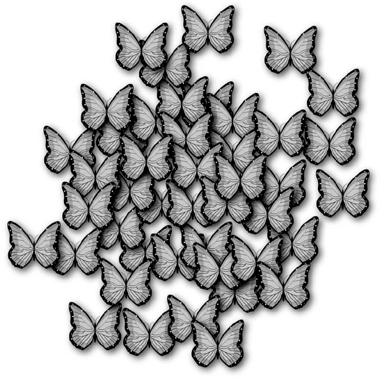
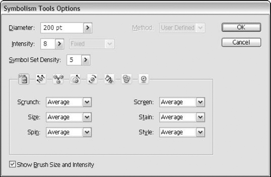
Figure 5.33. Use the Symbolism Tools Options dialog box to modify the way the Symbol Sprayer tool functions.
When you have a group of symbols, you can then alter them to look different. Editing the Symbol tools is done in the Symbolism Tools Options dialog box. Depending on the tool chosen from the icons along the top row, certain options might not be available. These options are:
Diameter: This sets the diameter of the sprayer in points.
Method: This sets the method to User Defined, Average, or Random. The User Defined method lets you manually scrunch, size, spin, screen, stain, and style the symbols. The Average method scrunches, sizes, spins, screens, stains, and styles the symbols by averaging the spaces between symbols. The Random method randomly scrunches, sizes, spins, screens, stains, and styles the symbols.
Intensity: This determines how many instances Illustrator sets when you use the mouse. Instances is the term for the number of symbols Illustrator sprays when you either click the mouse just once or hold the mouse button down for a period of time.
Pressure Pen: Use this dropdown list (popup menu) if you're using a pressure-sensitive tablet to choose the way that the Symbol Sprayer tool responds to different pen motions. This only appears if a pressure-sensitive pen is connected to your computer.
Symbol Set Density: This sets the density of the symbol set for the tools. Density determines how close together the symbols are.
Scrunch, Size, Spin, Screen, Stain, and Style: The Symbol Sprayer tool icon (on the far left) must be selected in order to access these options. Choose either User Defined or Average. The User Defined method lets you manually scrunch, size, spin, screen, stain, and style the symbols. The Average method scrunches, sizes, spins, screens, stains, and styles the symbols by averaging the spaces between symbols. The Random method randomly scrunches, sizes, spins, screens, stains, and styles the symbols.
Show Brush Size and Intensity: Click this check box to see the actual size and intensity of the brush when using the Symbolism tools.
If you don't like the default images available in the Symbols panel, you can create your own. It's as simple as making your own symbol and then adding it to the panel. You can either create a new symbol or use an existing symbol as a base.
To modify an existing symbol and then add it to the panel, follow these steps:
Click an existing symbol in the Symbols panel. You can access the Symbols panel by choosing Window
From the popup menu, choose Place Symbol Instance. You find this option by clicking the triangle on the upper-right side of the Symbols panel. Alternatively, you can simply click and drag the symbol from the panel to the page, as shown in Figure 5.34.
With the symbol selected, choose Object
Click OK to close the Expand dialog box. This turns the object back into editable strokes and fills.
Alter the object to your liking. You may need to use the Object
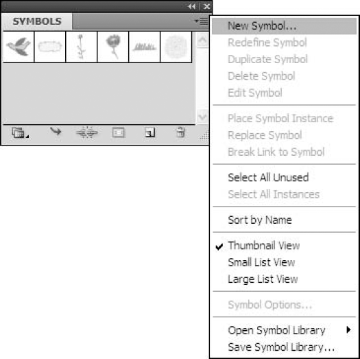
Turn it back into a symbol by choosing New from the Symbols panel's popup menu, as shown in Figure 5.35. Alternatively, you can drag the new symbol artwork over the Symbols panel, which also creates a new symbol.

You can also create your own new symbol. Simply draw the object you want as a new symbol and then drag it onto the Symbols panel (or choose New Symbol from the Symbols panel's popup menu). After you create a new symbol, you can use it the same way you use any of the built-in symbols.
Illustrator gives you lots of ways to edit your symbols after you spray them on your Artboard. These Symbol tools change the spacing between the objects, their size, color, transparency, style, and direction. Located eight tools down on the left side of the Tools panel, you access these tools by simply clicking and dragging to the tool you want.
To apply the effects of these tools, click the tool and then click the Artboard. Generally speaking, the longer you hold the mouse button, the more Illustrator applies the effect. For example, the longer you wait to release the mouse after clicking with the Symbol Scruncher tool, the more your image contracts. If you hold Alt (Option) while clicking one of these tools, it reverses the effect of the tool. For example, pressing Alt (Option) while clicking the Symbol Scruncher tool pulls symbols apart. These tools are available:
Symbol Shifter tool: Use the Symbol Shifter tool to totally move the symbols in the direction you drag. To change the stacking order with the Symbol Shifter tool, press Shift and then click the symbol to bring it forward. To send a symbol backward, hold Alt (Option) while pressing Shift and then click the symbol.
Symbol Scruncher tool: This tool changes the location of your symbols by pulling them together and changing the density distribution of the sprayed symbols.
Symbol Sizer tool: This tool increases the size of the symbols.
Symbol Spinner tool: You use this tool to move symbols to a new location. Simply click the Symbol Spinner tool and then drag the symbols in the direction you want them to go.
Symbol Stainer tool: The Symbol Stainer tool could possibly be the coolest Symbol tool of all. Use this tool to change the color of the symbols based on the Fill swatch in the Tools panel. Keep changing the color to make the symbols look totally different. The longer you hold the mouse pointer over the symbol, the more color is infused.
Symbol Screener tool: This tool changes the transparency of the symbols. The longer you apply this tool, the more the transparency.
Symbol Styler tool: Use this tool to apply a certain Style to a symbol. Choose the style from the Styles panel and then apply it to the symbol.
In this chapter, you learned how to use some of the more advanced and interesting drawing tools that Illustrator offers. These topics were covered:
Even the most basic shapes, such as the rectangle and ellipse, can create some pretty cool artwork.
The Flare tool can quickly add a highlight or create art on its own.
Illustrator has a variety of graph styles from which to choose.
You can always edit a graph's data as long as you don't ungroup the graph.
The Symbol Sprayer tool creates a bunch of objects quickly and efficiently.
Use the other Symbolism tools to alter the objects for variety.
Change any of the Symbol tool options to create just what you want.
You can alter the position, size, color, and transparency of the symbols at any time.