Understanding 3-D inside Illustrator
Extruding flat objects
Revolving paths around an axis
Adding highlights
Mapping 2-D onto 3-D objects
Creating depth and adding perspective has been the desire of many illustrators. This chapter shows how you can create three-dimensional images in Illustrator. Adding 3-D to your package design, logo, or any illustration is a breeze. Take any path, type, or object and then model it into a 3-D form, adding lighting and rotating it in three dimensions. Use 3-D to take your artwork to the next level. Imagine a logo in three dimensions rotating 360° on a Web site. The possibilities are endless.
One of the really cool features in Illustrator is the ability to create 3-D inside the application. You use the Extrude command to pop a two-dimensional item into a three-dimensional world. You can revolve a path into a three-dimensional object with highlights and even map artwork onto an image in 3-D. Not only can you revolve and extrude, but you can also rotate the object. Because your 3-D object is an effect, you can edit it at any time.
Take any flat shape and then add depth with 3-D, and you still retain all the editing abilities of the flat shape. Illustrator takes any changes you make later and incorporates them in the 3-D form. Using the Preview option, you can see what the object will look like. The extrude, revolve, rotate, and map artwork functions all appear in one neat dialog box.
In the past, Adobe offered Adobe Dimensions, which was a three-dimensional creation program. With Dimensions, you could extrude and revolve two-dimensional paths to create three-dimensional art. You could also add depth and lighting effects to make the object appear realistic. Most of Dimensions' capabilities are now inside Illustrator. The main difference in Illustrator is that you can't position multiple objects in 3-D space. You can only position one object at a time. And Illustrator creates the 3-D effect live rather than having to render, as Dimensions did.
Many 3-D packages are on the market, ranging from high-end software, such as Caligari trueSpace, 3ds max, and Maya, to low-end programs. They all handle transforming high-end 3-D into video, creating special effects, and making movies. And video artists use them in upscale game designs and animation. The low-end 3-D programs include Swift 3D, Poser, and Strata. Poser allows you to create 3-D models (people and animals) right down to the facial hair and realistic skin. Strata can create a model, render the 3-D, and animate the 3-D objects. Illustrator's 3-D abilities don't quite go that far, but it has come a long way for an illustrating program. Adobe took the three-dimensional qualities of Adobe Dimensions, created a cleaner, user-friendlier interface, and put it inside Illustrator.
The concept of three dimensions should be more intuitive and easy to understand because we are three-dimensional creatures who live in a three-dimensional world. But because most of our media are two-dimensional (reading, watching TV, working on a computer), adjusting to a three-dimensional digital world can be confusing and frustrating.
Television is a two-dimensional medium. The picture tube has height and width. Computer screens are two-dimensional. The pages of books are two-dimensional. Maps are two-dimensional, even though the world is round. Most people think in two dimensions.
Most of the two-dimensional objects that we deal with may very well be replaced with three-dimensional objects. Three-dimensional life will become a complete reality as soon as technology makes it so. Holograms have been around for a while, and technology is making them more accurate and lifelike. Video games and virtual-reality glasses already simulate three dimensions through the use of holograms and computer-generated imagery.
When you're trying to understand the concept of three dimensions on a computer screen, the most difficult aspect to grasp is depth. Left, right, up, and down are all simple concepts, but what about things that are closer or farther away? Maybe sometime in the future, we'll have to look up and down when we're driving.
Note
You're already thinking in three dimensions if you're familiar with Illustrator's Send to Back and Bring to Front commands. If you feel comfortable with stacking order and layers, then you're one step closer to working with three-dimensional positioning.
Note
For more on Send to Back and Bring to Front, see Chapter 8.
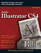
You use three indicators to position objects in the 3D Extrude & Bevel Options dialog box, which you access by choosing Effect
X is the object's horizontal location. A value greater than 0 means that the object is positioned to the right of center (0). A value less than 0 (any negative number) represents an object to the left of center.
Y defines the object's vertical position. A value that's greater than 0 means that the object is above center. A value that's less than 0 means that the object is below center.
Z represents the object's depth. This variable indicates how far forward or backward the object is from the center. A value less than 0 means that the object is behind 0, or farther away. A value greater than 0 means the object is in front of 0, or closer to you.
Figure 16.1 shows the X, Y, and Z values as you would see them initially in the 3D Extrude & Bevel Options dialog box. In the dialog box, relative X (horizontal), Y (vertical), and Z (depth) positions of selected objects can be rotated around those axes. In a direct, straight-from-the-front view, you can't determine an object's Z position. From the default position, which is a view of the object from above and to the right of the front, you can determine all three positions visually.
Illustrator's Extrude command adds sides, a top, and a back to an object. When extruding an object, you can fill the object or leave a hole in the middle (extruding the path but not the fill). Another option is to bevel the edges, which creates an amazing look for 3-D text.
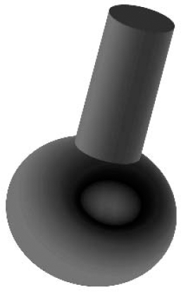
The Revolve command turns a path around a center axis, creating a 3-D effect in a circular fashion. This is a great way to create a bottle, a chess piece, or any other revolved shape. Not only can you apply light and shading to the revolved object, but you can map artwork directly onto the face of the object.
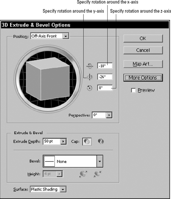
Extruding is the process of giving two-dimensional art depth that's equal on every part of the artwork. Figure 16.2 shows flat art and the same art extruded. When extruding art, you can retain the default depth (50 pt) or set the Extrude Depth slider to anywhere from 0 to 2000 points.
To create a basic extrusion on an object, follow these steps:
Create an object to extrude.
Select the object with the Selection tool. For more on selecting objects, see Chapter 6.
Choose Effect

Click the Preview box. This lets you see the default settings on your selected object.
Click OK. Illustrator applies the 3-D extrusion to your object by using the default settings (unless you made any changes in the dialog box).
You can choose these options in the 3D Extrude & Bevel Options dialog box:
Position: This lets you choose from a variety of positions for your selected object. Choose a view from the Front, Back, Left, Right, Top, Bottom, Off-Axis Back, Off-Axis Left, Off-Axis Right, Off-Axis Top, Off-Axis Bottom, Isometric Left, Isometric Right, Isometric Top, and Isometric Bottom. The default position is Off-Axis Front. You can also click and drag the box around to create a custom rotation.
Extrude Depth: This option lets you control how far in points the object's path is extruded. Drag the slider (which appears when you click next to the word Extrude) with the Preview button selected to see a live preview of the depth.
Cap: Choose whether to have the cap turned on for a more solid look or off for a hollow look.
Rotate: Use this option to rotate your object around the x-, y-, and z-axes.
Views: This option lets you change the view around the x-, y-, and z-axes.
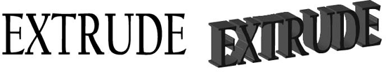
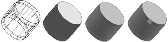
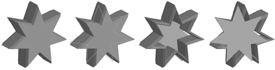
That was just a basic extrusion. There's so much more you can do. To begin with, you can cap or uncap an object (see Figure 16.3). Uncapping removes the front and back panes, making the object hollow. Capping puts front and back panes on the object, making the object solid.
Figure 16.3 shows a meeple with extrusion, lighting, and altered views applied in 3-D.
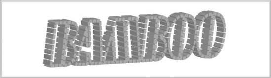
One visually appealing effect that you can achieve is to take a dashed-stroked line and use Extrude to make it 3-D. This technique creates a bamboo look or individual bars.
Note
3-D objects are inherently extremely visual subjects, and most of the changes you make to them are quickly visible in a preview. Rather than giving you exact settings to reproduce the objects shown in the illustrations, I suggest you experiment to achieve results that please you. Your final results probably won't look just like the illustrations, but you'll have fun and learn more about how the settings interact.
Follow these steps to extrude a dashed line:
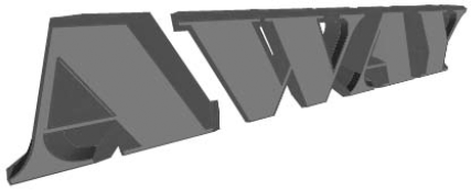
Create an object with a dashed line stroke and no fill. I used outlined text with a dashed stroke but no fill.
Choose Effect
Click the Preview check box. This lets you preview the image as you modify it.
Set the Extrude depth in points. Alternatively, you can click and drag the slider, change the views by picking an option from Position, or drag the box to a different view.
Click OK to see the extruded dashed lines. Figure 16.4 shows the resulting effect.
Tip
Try using any of the graphic styles (Window
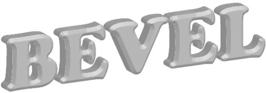
The use of bevels can make or break your artwork. Bevels give an edge to your 3-D object. You can use Illustrator's preset bevels or, if you feel ambitious, you can create your own bevel.
Follow these steps to add a bevel to an object:
Create an object to which you want to add 3-D.
Choose Effect
Choose a bevel from the Bevel dropdown list (popup menu).
Choose the height of the bevel and whether it bevels in or out. The height option is how large or small you want the bevel to be. You set this option by clicking and dragging the Height slider to a bevel in points. The other option is whether you want to add the bevel to the outside of the object or subtract it from the inside of the object. To make this determination, you click either the Bevel In button or the Bevel Out button.
Click the Preview check box to see the bevel. Leave the Preview check box deselected until you're done with your settings; otherwise, it may take awhile to preview your object.
Click OK to see the final results. Figure 16.5 shows the resulting bevel along the edge of the extruded path.
Although the preset bevels are good to use, you can also create your own custom bevel.
Follow these steps to add your own bevel to the Bevel list:
Make a copy of the
Bevels.aifile to use as a backup in case you munge the file accidentally.Open the
Bevels.aifile found in the Adobe Illustrator Plug-ins folder.Create the path you want to be your bevel in the
Bevels.aidocument.Turn that path into a symbol. Do this by choosing Window
Note
For more on symbols, see Chapter 5.
Rename the symbol. To rename the symbol, double-click the symbol in the Symbols panel. Type a name in the Symbol Options dialog box and then click OK.
Choose File
Quit Illustrator and then restart Illustrator. When you look at the Bevel list in the 3D Extrude & Bevel Options dialog box, your new bevel is listed there. You can now apply the custom bevel as you would any other bevel.
Revolving, also called lathing, is the process of spinning a 2-D object around an axis a specified number of degrees in order to create a 3-D object. You can create new objects by revolving different objects around different axes. You can create a lamp, a chess piece, a wedge of cheese, and more.
Follow these steps to revolve a path:
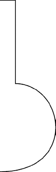
Draw a path with any of the drawing tools (Pen, Pencil, or Line Segment). Figure 16.6 shows a simple path. For more on the different drawing tools, see Chapter 4.
Select the path and then choose Effect
Click the Preview check box to see the revolved object displayed using the default settings.
Click OK to finish the revolving. Figure 16.8 shows the result of revolving the path you created. In this case, the object is tilted a little to better show off the effect.
The default option is to revolve the path 360°. You can change that to any number between 1 and 360. A number less than 360 creates an open section like a wedge taken out of a round of cheese.
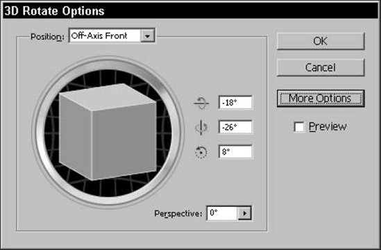
You can use the Rotate function found under an Effect submenu to rotate 2-D and 3-D objects. This rotation happens in 3-D space. This is a great way to apply a sheared effect or perspective to an object that's 2-D.
3-D rotation is done in its own dialog box. Choose Effect
Note
In most cases, you want to edit the existing effect by double-clicking it in the Appearance panel (Window
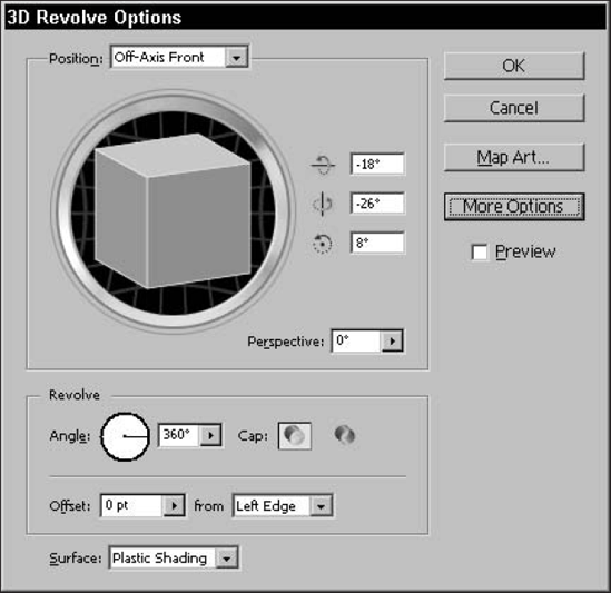
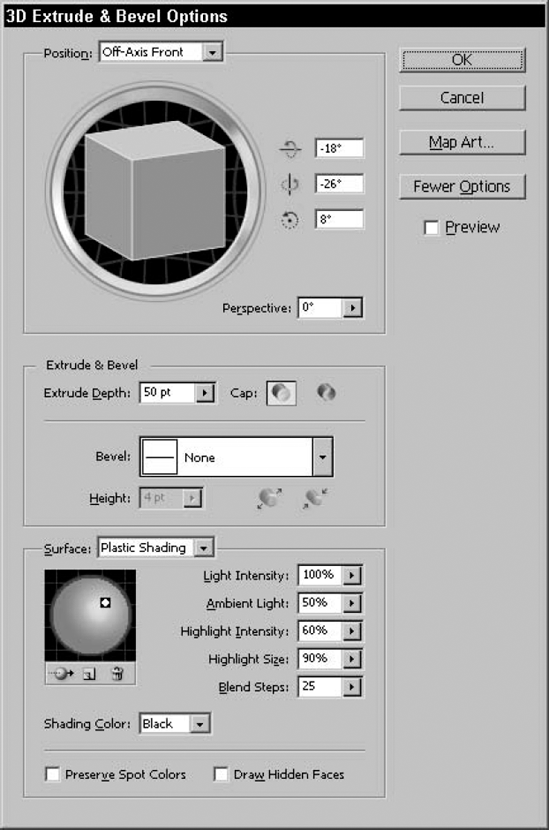
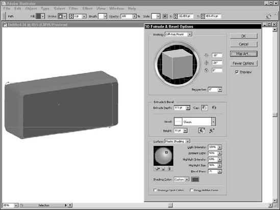
Objects created in the 3D Extrude & Bevel Options dialog box are not only colored but also lit. Additional specifications come with lighting: shading and reflectivity. You control the light by its surface characteristics. If you don't see any lighting options, click More Options on the right side of the 3D Extrude & Bevel Options dialog box. This opens the shading and light areas, as shown in Figure 16.10.
The Surface properties control the look of the outside surface of the 3-D object. You can create 3-D objects that are just outlined, have no shading, have soft shading, or have intense, glossy shading. Your options are Wireframe, No Shading, Diffused Shading, and Plastic Shading. Figure 16.11 shows one object with each of the following surface characteristics applied to it:
Wireframe traces the curves of the object's geometric shape and fills the shape with transparent fill (there are no lighting options with this surface characteristic).
No Shading fills the object with the same color as the original 2-D object (there are no lighting options with this surface characteristic).
Diffuse Shading adds a soft diffused light source on the object's surface.
Plastic Shading adds a bright shiny light as if the object were made of plastic.
Lighting can be a little confusing in a 3-D program. Because lights in 3-D are positioned an infinite distance from objects, shading for different objects is the same, no matter what the position of the objects. For example, if the lights are in the upper left, objects on the far left have the same lighting as objects on the far right. If the lights were positioned closer, the shading would appear differently.
A good way to think of the lights that you create is that they resemble sunlight to us earthbound creatures. Light from the sun shines on an object in New York City almost exactly the same way it shines on an object in Boston. Because the sun is so far away, the difference in the position of the sun relative to the two cities is minute. If the sun were an infinite distance away and Earth were flat, the two cities would have exactly the same sunlight.
Because there are no shadows in Illustrator's 3D Extrude & Bevel Options dialog box, objects that are between the light source and another object let light pass through them so that the light can reach the hidden object.
In the lighting sphere in the 3D Extrude & Bevel Options dialog box, you can set a variety of lighting choices on your object. These buttons appear below the lighting preview sphere from left to right: Move selected light to back of object, New Light, and Delete Light.
You have these lighting options for Diffuse Shading or Plastic Shading:
Light Intensity controls how intense the light is. The values are from 0 to 100.
Ambient Light changes the brightness of all the surfaces of an object. The values are from 0 to 100.
Blend Steps adjusts how smooth the shading flows across an object. A lower number creates a more matte look. A higher number creates a glossy, shiny look.
If you're just using Plastic Shading, you can use these additional options:
Along with the lighting is the Shading Color. The default is Black, but you can choose Custom, click the swatch that appears, and access the color picker, where you can choose any color you want.
Note
For more on color, see Chapter 7.
The lighting sphere shows the light on a surface. You can move the light around by dragging it to a new location. By clicking the New Light icon (the one in the middle), you can add additional lights to the surface. The active light has a box around it. Each light can have different settings applied to it.
Note
The default setting is that all 3-D objects must have one light. You can add as many as you want in addition to the default.
The trash icon (on the right) lets you delete lights. Select a light and then click the trash icon to delete the light. The first button is Move selected light to back of object. It sends that light behind the object for backlighting. Figure 16.12 shows an object with different lighting features applied to it.

Figure 16.12. This figure shows an object with different lighting effects applied by using the lighting options in the 3D Extrude & Bevel Options dialog box.
Spot colors are automatically changed to process colors unless you click the Preserve Spot Colors check box. When you click the Draw Hidden Faces check box, you can view the back faces through transparent surfaces.
The Appearance panel works wonders with 3-D objects. If you have complex artwork with a 3-D effect applied, you can reduce screen redraw time by clicking the eyeball (hiding the effect) in the Appearance panel. If you have an object with multiple strokes and fills and 3-D, try moving the 3-D entry to different areas of the Appearance panel. Move it above a fill or under a stroke, and see how different the object can look. Figure 16.13 shows an object with multiple attributes. I moved the 3-D section to different areas to create different looks.
One of the most powerful features of 3-D is the ability to wrap 2-D objects around 3-D surfaces. This feature alone makes upgrading or buying Illustrator worth the money. The mapping feature is a great way to add a label to a bottle or any type of package design. Now your clients can see how their product looks before printing and packaging.
The most important concept to understand when you're mapping artwork is that each 3-D object usually has several different surfaces, and each of those surfaces can have separate mapped artwork. The key to mapping 2-D to 3-D is to make a map out of the 2-D object that you want to use and then turn it into a symbol. Any of Illustrator's symbols can be mapped onto 3-D objects.
Follow these steps to create a 3-D map out of a 2-D object:
Create the text (or another object) that you want to map onto 3-D art.
Drag the created text into the Symbols panel. This makes the text a new symbol. See instructions earlier in this chapter for adding symbols to the Symbols panel. For more on symbols, see Chapter 5.
Create the path that you want to turn into 3-D. I chose a path to indicate a sign.
Choose Effect
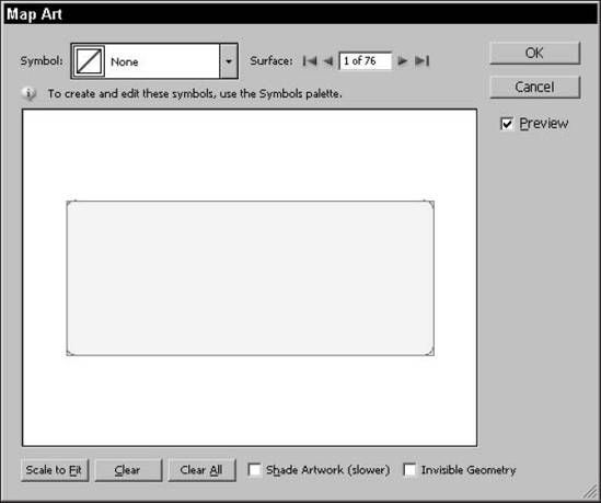
Click Map Art to display the Map Art dialog box, as shown in Figure 16.15. In this dialog box, you can see the number of surfaces on the object, starting with surface 1.
Choose the surface that you want to map.
Note
As you choose a surface, the original highlights in red wireframe the surface you're selecting to make it easier for you to see where the mapping will occur.
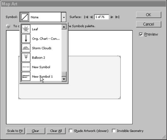
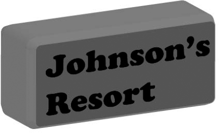
When you have the surface that you want to map, choose a symbol from the Symbol menu. The symbol you created is listed there, as shown in Figure 16.16.
After you choose the art for all the surfaces, click OK to exit the Map Art dialog box.
Change the rotation or axis view if you want.
Click OK. The final results are shown in Figure 16.17.
When you choose a symbol in the Map Art dialog box to map, the symbol appears in the center of the screen with a Bounding Box around it. This box gives you the ability to stretch, rotate, or move the object to fit the area you want.
The Map Art dialog box also has a Preview check box, which allows you to see the object mapped onto the shape. A cool thing to do is to use a cube and then map artwork on all surfaces of the cube to make custom dice. You could use the dice in animation for a Web page.
Note
For more on creating art for the Web, see Chapter 19.
The Map Art dialog box has several other useful features:
Surface: All the object's surfaces are listed here. Apply mapped art to one surface or as many as you want.
Scale to Fit: Choose this option to scale the mapped artwork to fit the whole surface.
Clear: Use this to remove mapped artwork from the selected surface.
Clear All: Use this to remove all mapped artwork from all surfaces.
Shade Artwork (slower): This option shows the mapped artwork along with the shade and lighting applied. A preview takes longer with this option selected.
Invisible Geometry: Clicking this check box previews just the mapped art on the object, with the object showing in wireframe.
Using Illustrator's 3-D effects isn't the only way to create depth in illustrations. You can do many things in Illustrator to create the illusion of depth. Drop shadows (Effect
When you place gradients on themselves and one gradient has a different direction than another, 3-D effects appear. If you remember that highlights reflect off surfaces that bounce light to your eye, that principle should help you determine the direction of the gradients.
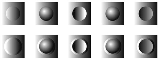
Of course, whether an object is coming at you or going away from you should be obvious, shouldn't it? Figure 16.18 shows ten buttons. See whether you can determine which buttons are innies and which buttons are outies. To assist you further, each button is on a standard background and has a button ring. The ring makes the direction of several of the buttons quite obvious.
Another newer aspect to Illustrator is the addition of perspective. The perspective option is found in the 3D Extrude & Bevel Options dialog box. This option gives your 3-D object a perspective look. The perspective option ranges from 0° to 160°. The perspective is a simulated distance from the object in the actual file, as shown in Figure 16.19.
Creating 3-D objects from 2-D ones really brings your Illustrator documents alive. In this chapter, you learned about Illustrator's 3-D effects, including the following:
You can extrude or revolve 2-D objects to create 3-D objects.
You can add multiple lights and change the color of the shading on a 3-D object.
You can change the surface characteristics to be wireframe, no shading, diffuse shading, or plastic shading.
You can map 2-D artwork onto 3-D objects.
Layering gradients creates a 3-D look.