Rotating, reflecting, shearing, scaling, and reshaping with tools
Using the Transform panel
Creating cool effects with the Liquify tools
Distorting objects
Creating distortion effects
Adding distortions with warps
I llustrator has the capability to transform any object by scaling it, rotating it, reflecting it, shearing it, or reshaping it. In this chapter, you learn how to take advantage of this power by using transformation functions with menus, panels, and certain tools.
In addition to transformations, Illustrator really gets fun when you work with distortions. Distortions are accomplished with a number of different effects, warps, and the amazing Liquify tools.
Although there are many places to find the transformation functions, the first stop is the transformation tools. The transformation tools in the Tools panel address fundamental functions, such as scaling, rotating, reflecting, shearing, and reshaping. Before you can use any of these tools, however, you must select one or more objects (including paths, points, and segments). The selected paths are the paths that are transformed.
Using the various transformation tools, you can transform selected objects in five ways:
Click with a transformation tool to set an origin point and then drag from a different location. This is called a manual transformation.
Click and drag in one motion to transform the object from its center point or last origin point.
Press Alt (Option), click to set the origin, and then type exact information in the tool's dialog box. This method is more precise than manually transforming.
Double-click a transformation tool to set the origin in the center of the selected object and then type information in the tool's dialog box.
Use the Transform panel (discussed later in this chapter).
All the transformations have additional options in their dialog boxes. Clicking Copy makes a copy of the original and then transforms it to your settings. Clicking the Object check box applies the transformation only to the object (not the fill pattern inside). Clicking the Pattern check box applies the transformation to just the pattern (not the object). Clicking both check boxes applies any transformations to both the object and the pattern.
All the transformation tools work on an accumulating basis. For example, if you scale an object 150% and then scale it again by 150%, the object becomes 225% of its original size (150% × 150% = 225%). If the object is initially scaled to 150% of its original size and you want to return it to that original size, you must do the math and figure out what percentage you need to resize it — in this case, 66.7% (100% ÷ 150% = 66.7%) — or you could just use the Undo feature. Typing 100% in the Scale dialog box leaves the selected objects unchanged.
Illustrator automatically creates a visible origin point, as shown in Figure 11.1, when you use any of the transformation tools. Because the origin is in the center of the selection, if you just click and drag with a transformation tool, the origin point is visible as soon as you click a transformation tool. If you click without dragging to set the origin, it appears at that location until the origin is reset. Having the origin point visible as a blue crosshair makes the transformation tools much more useable and functional.
When manually transforming objects, you can make a copy of the selected object — and thus leave the original untransformed — by holding Alt (Option) before and after releasing the mouse button. In a transformation tool's dialog box, you can make a copy by clicking Copy.
If the Patterns check box is available (you must have a pattern in one of the selected paths; otherwise, this option is grayed out) in any of the transformation tool dialog boxes, you can click its check box to transform your pattern and the object. You can also transform the pattern only, leaving the object untransformed, by deselecting the Objects check box.
Note
For more on patterns, see Chapter 10.
Tip
You can manually transform just patterns (and not the objects themselves) by pressing the grave (`) key while using any of the transformation tools, including the Selection tool.
Manually transforming objects is fairly simple if you remember that the first place you click (the point of origin) and the second place should be a fair distance apart. The farther your second click is from the point of origin, the more control you have when dragging to transform.
All the transformation tools perform certain operations that rely on the Constrain Angle as a point of reference. Normally, this is set to 0°, which makes your Illustrator world act normally. You can change the setting by choosing Edit (Illustrator)
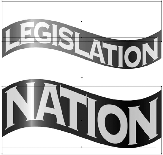
You can access each of the transformation tool dialog boxes by choosing Object
Note
If the Bounding Box (the blue box that surrounds selected objects) is visible (View
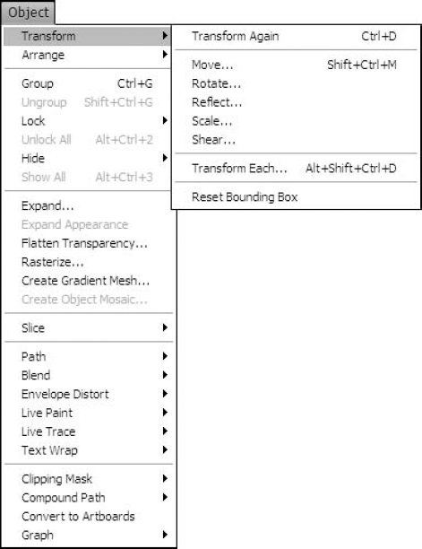
The Rotate tool is found in the Tools panel, and it rotates selected objects within a document. Double-clicking the Rotate tool or choosing Object
Click once to set the origin point, which is the object's center of rotation, and then click fairly far from the origin and drag in a circle. The selected object spins along with the cursor. To constrain the angle to 45° increments as you drag, press and hold Shift. This angle is dependent on the Constrain Angle box and is in 45° increments plus the angle in this box. Figure 11.4 shows an illustration before and after rotation.

The Reflect tool makes a mirror image of the selected objects, reflected across an axis of reflection. You can find the Reflect tool as a popup tool under the Rotate tool. Double-clicking the Reflect tool or choosing Object
Note
Pressing Alt (Option) and then clicking in the document window with the Reflect tool selected also opens the Reflect dialog box; however, the axis of reflection is now not in the center of the selected object but passes through the location in the document where you Alt (Option)+clicked.
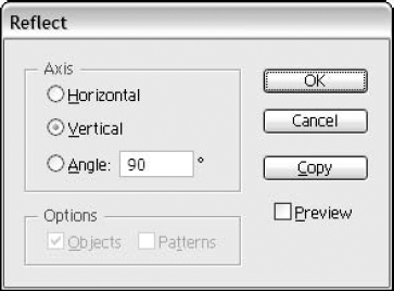
Manual reflecting is done by clicking once to set the origin point (the center of the axis of reflection) and then again somewhere along the axis of reflection. If you click and drag after setting your origin point, you can rotate the axis of reflection and see what your objects look like reflected across various axes. Pressing Shift constrains the axis of reflection to 90° angles relative to the Constrain Angle. Holding Alt (Option) during the release of the click leaves a copy of the original object. Figure 11.6 shows an illustration before and after being reflected.
The Scale tool resizes objects either uniformly or nonuniformly. You can also use the Scale tool to flip objects but without the precision of the Reflect tool. It's impossible to keep both the size and proportions of an object constant while flipping and scaling using the Scale tool.
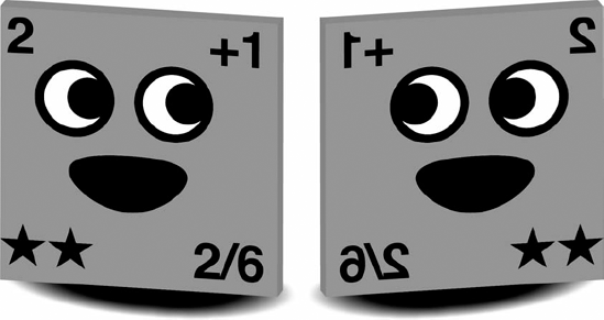
Double-clicking the Scale tool or choosing Object
Nonuniform scaling resizes the horizontal and vertical dimensions of the selected objects separately, distorting the image. Nonuniform scaling is related to the Constrain Angle you set in the General Preferences dialog box; the angle set there is the horizontal scaling, and the vertical scaling is 90° from that angle.
Tip
Pressing Alt (Option) and then clicking in the document window with the Scale tool selected also opens the Scale dialog box, but the objects are now scaled from the location in the document that was Alt (Option)+clicked.
You can achieve manual resizing by clicking your point of origin and then clicking away from that point and dragging to scale. If you cross the horizontal or vertical axis of the point of origin, the selected object flips over in that direction. Holding Shift constrains the objects to equal proportions if you drag the cursor at approximately 45° from the point of origin. Alternatively, holding Shift constrains the scaling to either horizontal or vertical scaling only if you drag the cursor at about a 90° angle from the point of origin relative to the Constrain Angle.
You find the Shear tool as a popup tool under the Scale tool. The Shear tool is somewhat tricky to use until you get the hang of it. Essentially, it pulls all points above the origin point to the side and pushes all points below the origin point in the opposite direction. The farther the points are from the origin, the farther to the side they're moved. The effect gives a slanted, perspective-like look to your object. Use the Shear tool to add a shadow to an object or text. Another great use of shear is to make an object or text look like it's in perspective.
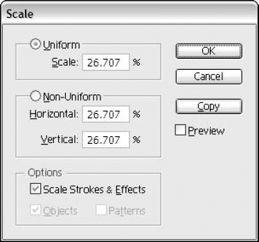
Double-clicking the Shear tool opens the Shear dialog box, as shown in Figure 11.8, which allows more precise control. Double-clicking causes the origin to be in the center of the selected object. The Shear Angle box is simple enough; you type the angle amount the object should shear. Any amount over 75° or less than −75° typically renders the object into an indecipherable mess because at this angle or higher, the art has been flattened into a straight line. The Shear tool reverses the positive-numbers-are-counterclockwise rule.
To shear an object clockwise, type a positive number; to shear counterclockwise, type a negative number. The Axis Angle box is for shearing an object along a specified axis, as opposed to the standard 0/45/90 angle.
Tip
Pressing Alt (Option) and then clicking in the document window with the Shear tool selected also opens the Shear dialog box, with the origin of the shear being the location of the Alt (Option)+click.
Manual shearing is something else again because while you click, hold, and drag with the Shear tool, you're doing two things at once. From the beginning of the second click until you release the mouse, you change the angle of shearing. Usually, it's best to start your second click fairly far away from the point of origin. Pressing and holding Shift constrains the axis of shearing to a 45° angle relative to the Constrain Angle. Figure 11.9 shows an illustration before and after being sheared.
You use the Reshape tool to select one or multiple anchor points in order to change an object's shape. You can also select parts of paths to change. Located as a popup tool under the Scale tool, you use the Reshape tool on any path by clicking where you want to bend the path and then dragging. To use the Reshape tool on several paths at once, use the Reshape tool to select the points you want to move first. You must select at least one point that isn't a straight corner point on each path. You then drag on a selected point; all the curved points also move. Figure 11.10 shows an example of what the Reshape tool does.
Tip
The Reshape tool works best on curved objects, such as spirals, ovals, etc.
The most common way to move an object is to use a selection tool and then drag the selected points, segments, and paths from one location to another.
The precise way to move an object is to use the Move dialog box, as shown in Figure 11.11, or the Transform panel (discussed later in this chapter). Select the object you want to move and then choose Object
You can move any selected object (except for text selected with a Type tool) via the Move dialog box, including individual anchor points and line segments.
By default, the Move dialog box contains the distance and angle that you last moved an object, whether manually with a selection tool or in the Move dialog box. If you use the Measure tool (found in the Tools panel) prior to using the Move dialog box, the numbers in the Move dialog box correspond to the numbers that appeared in the Info panel (choose Window
Tip
Double-clicking the Selection tool in the Tools panel also opens the Move dialog box.
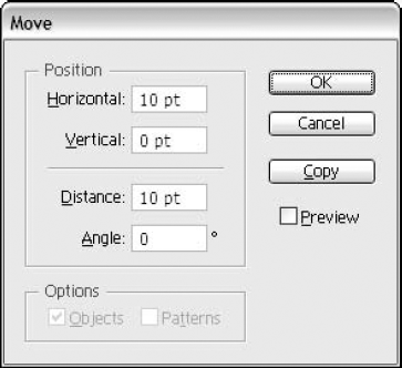
Figure 11.11. The Move dialog box allows you to specify an exact distance and direction to move objects.
In the Move dialog box, positive numbers in the Horizontal text field move an object to its right, while negative numbers move an object to its left. Positive numbers in the Vertical text field move an object up, while negative numbers move an object down. Negative numbers in the Distance text field move an object in the opposite direction of the Angle text field. The Angle text field works a bit differently. Negative numbers in the Angle text field move the angle in the opposite direction from 0°, so typing −45° is the same as typing 315 and typing −180 is the same as typing 180.
The measurement system in the Move dialog box uses the units set in the General Preferences dialog box. To use units other than those of the current measurement system, use these indicators:
For inches: 1″, 1in, or 1 inch
For picas: 1p, 1pica, or 1 pica
For points: 1pt or 1 point
For picas/points: 1p1, 1 pica, or 1 point
For millimeters: 1mm or 1 millimeter
For centimeters: 1cm or 1 centimeter
The Horizontal and Vertical text fields are linked to the Distance and Angle text fields; when you change one of the Horizontal or Vertical fields, Illustrator alters the Distance and Angle fields accordingly.
Clicking Copy duplicates selected objects in the direction and distance indicated, just as holding Alt (Option) when dragging duplicates the selected objects.
Tip
The Move dialog box is a great place to type everything via the keyboard. Press Tab to move from text field to text field, press Enter (Return) instead of clicking OK, and press Esc (
Free Transform allows you to rotate, scale, reflect, and shear all with one tool. This way, you can create multiple transformations at one time. The Free Transform tool is located directly below the Scale tool in the Tools panel.
What is unique about this tool is that you can select more than one object to change the size, shape, and placement in one step. The Free Transform tool doesn't replace the Free Distort effect. Using this cool tool to create distorted effects is different from using the Free Distort effect.
Note
For more on the Free Distort effect, see Chapter 11.
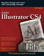
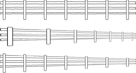
At first glance, they may seem the same, but they aren't. The Free Transform tool actually adds perspective, while the Free Distort effect mimics the shape but keeps the spacing uniform. This sounds confusing, but the visual example in Figure 11.12 may help. The middle image shows the application of the Free Transform tool to the top and bottom of the fence. This gives a tree-line effect with perspective. The bottom image shows the application of the Free Distort effect to the top and bottom of the fence. Note the different results.
Tip
To apply the Free Transform tool to the top and bottom of an image at the same time, hold Alt (Option). For more control, hold Ctrl (
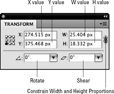
Imagine a panel that combines four of Illustrator's five transformation capabilities into one place. Then, look at Figure 11.13, which shows Illustrator's Transform panel in all its glory.
The Transform panel provides a way to move, scale, rotate, and shear selected artwork. You don't have a Reflect option; you need to use the tool or the Transform submenu option to reflect artwork. Instead of manually setting an origin point or transforming from the center by default, the Transform panel gives you nine fixed origin points based on the Bounding Box of the selected objects. You can select these fixed origin points by using the square set of points in the right side of the panel. Choose an origin point before typing values in the panel, and the transformations originate from the corner, the center of a side, or the center of selected objects.
The text fields in the Transform panel are as follows:
X: This is the horizontal location of the artwork, measured from the left edge of the document or horizontal ruler origin (if it's been moved from the left edge).
Y: This is the vertical location of the artwork, measured from the bottom edge of the document or vertical ruler origin (if it's been moved from the bottom edge).
W: This is the width of the artworks Bounding Box.
Rotate: This field lets you apply a rotation to the selected artwork.
Shear: This field lets you apply a shear to the selected artwork.
To use the panel, type the new value you want to use into any text field and then press Enter (Return). If you have another value to type, press Tab to go to the next text field or Shift+Tab to go back a text field. Pressing Alt (Option) when you press Enter (Return) or Tab creates a duplicate of the selected artwork with the transformations you specified.
For scaling, you can type either absolute measurements (the size in inches, picas, etc., that you want the artwork to be) or as a percentage by adding the percent (%) symbol after your value. You can also force Illustrator to scale uniformly, regardless of whether you're using absolute measurements or percentages, by clicking Constrain Width and Height Proportions on the right side of the panel.
Transform Each provides a way to do several transformations in one shot, but that's only the beginning. The unique thing about Transform Each is that each selected object is transformed independently, as opposed to having all the selected objects transformed together. Figure 11.14 shows the difference between normal rotating and scaling and the rotate and scale functions in Transform Each.
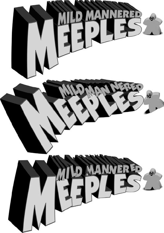
Figure 11.14. The original logo (top) and changes applied using the Transform Each dialog box (middle) as well as with changes using the Random check box (bottom)
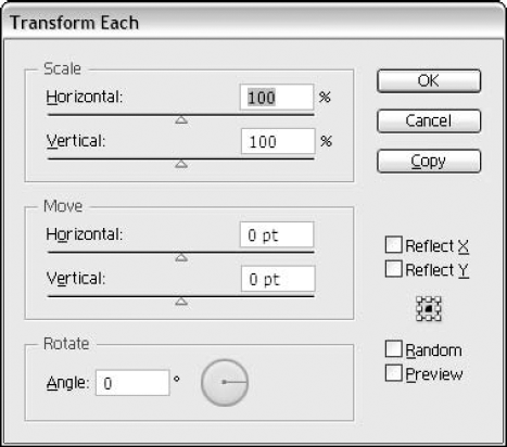
To access the Transform Each dialog box, as shown in Figure 11.15, choose Object
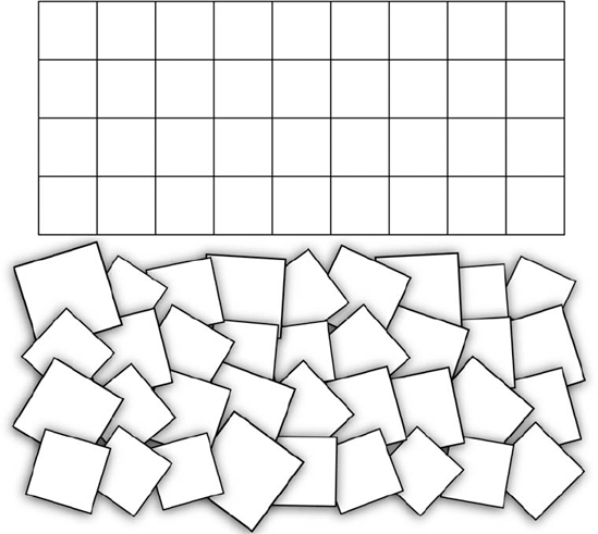
In addition to controls for setting the Scale, Move, and Rotate values, the Transform Each dialog box includes check boxes to reflect the selected objects about the x- or y-axis and an icon for selecting an origin point. But of all the offerings, the Random option of Transform Each is its most powerful asset. Clicking the Random check box can turn a grid into a distinct random texture, as shown in Figure 11.16.
The transformation tools open a world of possibilities within Illustrator. The following tips and ideas should give you a head start in exploring the amazing power of transformations.
Choosing Object
Tip
Transform Again remembers the last transformation no matter what else you do, and it can apply that same transformation to other objects or reapply it to the existing transformed objects.
You can create all sorts of shadows by using the Scale, Reflect, and Shear tools. To create a shadow, follow these steps:
Select the path where you want to apply the shadow.
Click the bottom of the path once with the Reflect tool. This sets the origin of reflection at the base of the image.
Drag the mouse down while pressing Shift. The image flips over, creating a mirror image under the original.
Press Alt (Option) while keeping Shift pressed before and during the release of the mouse button. This makes a copy of the image.
Using the Shear tool, click the base of the reflected copy to set the origin.
Click and drag left or right at the other side of the reflection. This sets the angle of the reflection.
Using the Scale tool, click once again on the base of the reflected copy to set the origin.
Click and drag up or down at the other side of the reflection. This sets how far away from the original object the shadow falls.
Color the shadow darker than its background. The resulting shadow is shown in the illustration in Figure 11.17. You may have to experiment with these steps a bit to achieve the results you really want.

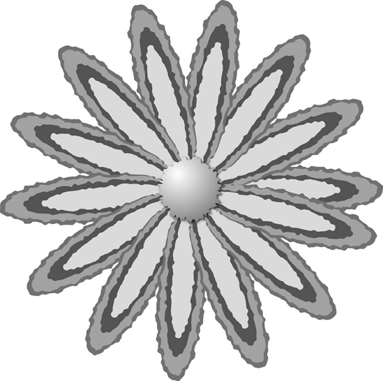
Clever use of the Rotate tool can create a unique-looking flower, as demonstrated in these steps:
Start by creating a few overlapping ellipses and then group them together.
Select the group of ellipses and then choose Effect

Click the Rotate tool.
Click to set an origin near one of the ends of the ellipse.
Click the other side of the group and then drag. As you drag, the outline of the shape of the objects that you're dragging appears.
When the ellipses have been rotated until they're only partially overlapping the original group, press Alt (Option). This copies the group.
Release the mouse button and then release Alt (Option). A copy of the group appears.
Press Ctrl+D (

Draw a circle in the middle of the petals and then fill it with a gradient.
Figure 11.18 shows the final flower. The farther you click from the ellipses to set the origin, the smaller the curve of the path of objects. Clicking right next to the objects causes them to turn sharply.
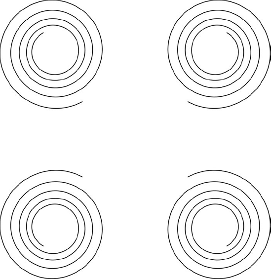
You can make symmetrical tiles with the Reflect tool. You can use a set of four differently positioned yet identical objects to create artwork with a floor-tile look. To do this, follow these steps:
Create the path (or paths) that you'll make into the symmetrical tile.
Group the artwork together by selecting the artwork first and then choosing Object
Click the Reflect tool and then click off to the right of it to set the origin.
Click and drag on the left edge of the object and then drag to the right while pressing Shift+Alt (Option). Using Shift reflects the image at only 45° angles.
When the object has been reflected to the right side, release the mouse button while still pressing Alt (Option) and then release Alt (Option). You now have two versions of the object.
Select the original and reflected objects and then reflect again across the bottom of the objects. You now have four objects — each mirrored a little differently — that make up a tile. You can use this tile to create symmetrical patterns.
The resulting tile pattern is shown in Figure 11.19.
When using the transformation tools, you don't need to select an entire path. Instead, try experimenting with other effects by selecting single anchor points, line segments, and combinations of selected anchor points and segments. Another idea is to select portions of paths on different objects.
Tip
When you're working with portions of paths, one of the most useful transformation tool procedures is to select a smooth point with the Direct Selection tool and then choose a transformation tool.
You can achieve precise control with the Rotate tool. Click the center of the anchor point and then drag around it. Both control handles move, but the distance from the control handles to the anchor point remains the same. This task is very difficult to perform with just the Direct Selection tool, which you can also use to accomplish the same task.
You can accomplish the exact lengthening of control handle lines by using the Scale tool. Click the anchor point to set the origin and then drag out from one of the control handles. Both control handles grow from the anchor point in equal proportions.
When working on a smooth point, you can use the Reflect tool to switch lengths and angles between the two control handles.
Here are some more portion-of-path transformation ideas:
Select all the points in an open path except for the endpoints, and use all the different transformation tools on the selected areas.
Select the bottommost or topmost anchor point in text converted to outlines, and scale, rotate, and shear for interesting effects.
Select two anchor points on a rectangle, and scale and skew copies into a cube to create a 3-D appearance.
The option in all transformation tool dialog boxes and the Move dialog box to apply transformations to patterns can produce some very interesting results, as shown in Figure 11.20.
One of the most interesting effects results from using patterns that have transparent fills. Select an object that has a pattern fill and then double-click a transformation tool. Type a value, click the Patterns check box, deselect the Objects check box, and then click Copy. A new unchanged object overlaps the original object, but the pattern in the new object has changed. If desired, use the Transform Again command by pressing Ctrl+D (
Illustrator has another group of tools called the Liquify tools, which includes the Warp, Twirl, Pucker, Bloat, Scallop, Crystallize, and Wrinkle tools. These tools are housed with the Warp tool (a finger smushing a line) in the Tools panel. The Liquify tools give you freeform morphing abilities unlike any other drawing tools.
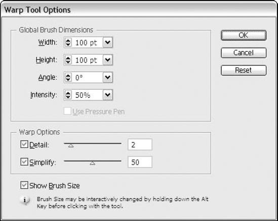
All these tools work with a brush interface. You can alter the brush options and the individual tool options by double-clicking the active tool. Figure 11.21 shows the Warp Tool Options dialog box. With all the Liquify tools, you can always adjust the Global Brush Dimensions and even set it to use a pressure pen. For all the tools, just click and drag them on any selected artwork to achieve the effect.
The Global Brush Dimensions section includes settings for the Width, Height, and Angle of the brush. The Intensity setting controls how hard you need to move against the path before a change appears. Using the Warp Options section, you can control the Detail and Simplify settings for each of the Liquify tools.
Tip
Change the brush size while applying the tools by holding Alt (Option) before clicking with the tool. This allows you to drag the circle (brush) size out or in before you use the tool.
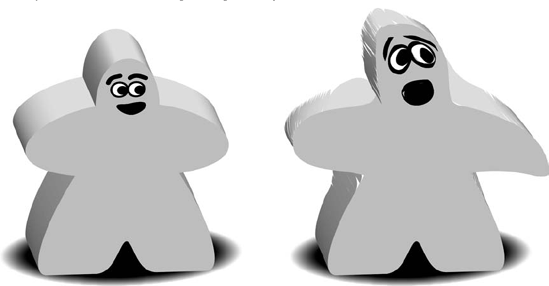
The Warp tool treats objects like modeling clay. You stretch, drag, or pull areas of an object. Figure 11.22 shows the original object on the left and the warped one on the right. You can push out the shape by dragging outward. Put dents in the object by dragging from the outside in.
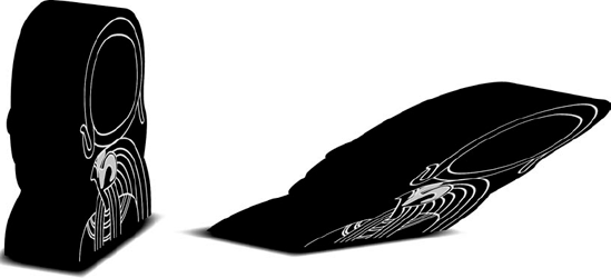
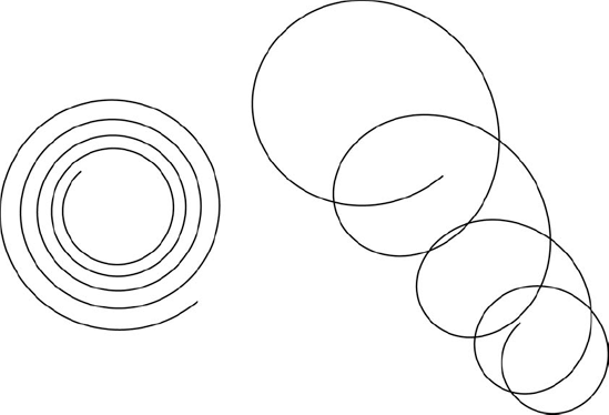
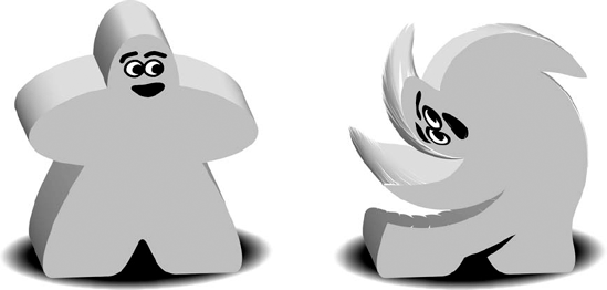
The Twirl tool applies a spiraled effect to the object. Use this to swirl and ripple distortions on your artwork. Figure 11.23 shows the original object on the left and the swirled object on the right.
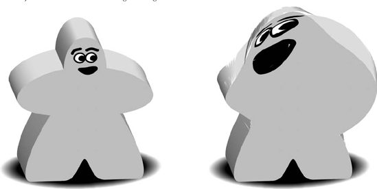
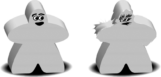
The Pucker tool is similar to the Pucker & Bloat effect (covered later in this chapter). Using this tool in a brush fashion applies a pinched or pulled-in look with spikes, as shown in Figure 11.24.
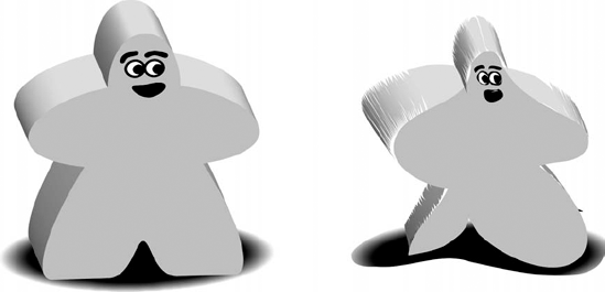
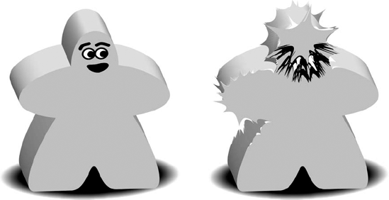
The Bloat tool, like the Pucker tool, is similar to its effect counterpart. Use this to bulge out or puff out in a brushed, controlled fashion. Figure 11.25 shows the original object on the left and the bloated object on the right.
The Scallop tool is used to add arc shapes to your object. This tool randomly brushes arc shapes along the area you brush over. Figure 11.26 shows the original object on the left and the scalloped object on the right.
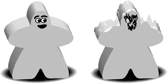
The Crystallize tool applies arcs and spikes by using a brush on the object. Click and drag outward to push the path out. Click and drag inward to push the path inward. The object doesn't have to be selected; simply drag the brush over the top of the object you want to crystallize. Figure 11.27 shows an example of what this tool can do.
The Wrinkle tool applies a roughened edge to your artwork, similar to the Roughen effect but applied in a brush fashion. Figure 11.28 shows an application of the Wrinkling tool.
Note
For more on the Roughen effect, see Chapters 5 and 6.
Effects provide changes in appearance to selected objects. You can go back and edit or remove just the effect without losing any of your other applied options.
Note
For more on effects, see Chapter 15.
All effects are fully editable via the Appearance panel. In the following examples, the commands used are those found by choosing Effect
The first of the distortion effects is the Free Distort. This was discussed briefly with the Free Transform tool earlier in this chapter. The big difference between the Free Transform tool and the Free Distort command is that Free Distort keeps the spacing relevant and doesn't use the perspective as the Free Transform tool does.
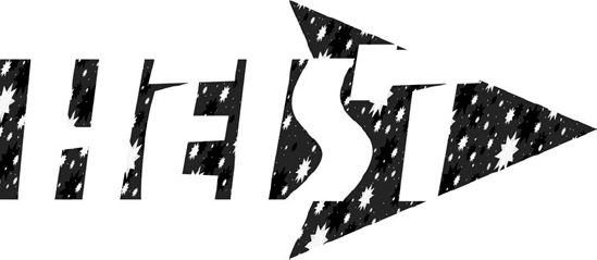
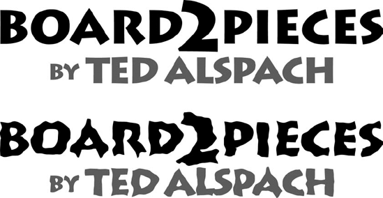
The Free Distort command allows you to alter the shape of the selected object by dragging four corner points. Some may think of this as enveloping, but it's a much simpler effect. Figure 11.29 shows text that has the Free Distort command applied to it.

Although the Pucker & Bloat command undoubtedly has the coolest sounding name that Illustrator has to offer, this command is also one of the least practical. But Illustrator is a fun program, right? And these commands make it lots of fun.
Puckering makes objects appear to have pointy tips sticking out everywhere, and bloating creates lumps outside of objects. Puckering and bloating are inverses of each other; a negative pucker is a bloat, and a negative bloat is a pucker. If you're bewildered by these functions, stop reading right here. The following information spoils everything.
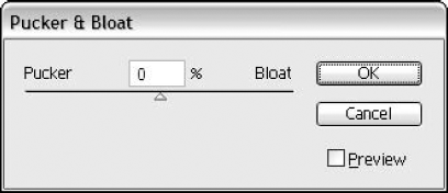
Choosing Pucker & Bloat opens the Pucker & Bloat dialog box, as shown in Figure 11.30, where you can specify a percentage by which you want the selected paths to be puckered or bloated by either typing the amount or dragging the slider.
Bloating causes the segments between anchor points to expand outward. The higher the percentage, the more bloated the selection is. You can bloat from −200 to +200. Using Bloat makes rounded, bubble-like extrusions appear on the surface of your object; using Pucker makes tall spikes appear on its path. When you drag toward Pucker, you can type how much you want to pucker the drawing. Pucker amounts can range from −200 to +200. The number of spikes is based on the number of anchor points in your drawing. Figure 11.31 shows the original text (top), the text being puckered (middle), and the text being bloated (bottom).
Note
Text is great to play with using these distortion commands because it's still fully editable. You don't have to create outlines first.
The Pucker & Bloat command moves anchor points in one direction and creates two independent direction points on either side of each anchor point. The direction points are moved in the opposite direction of the anchor points, and the direction of movement is always toward or away from the center of the object.
The distance moved is the only thing that you control when you use the Pucker & Bloat command. Typing a percentage moves the points that percentage amount.
Note
Nothing about the Pucker & Bloat command is random. Everything about it is 100% controllable and, to some extent, predictable.
Roughen adds anchor points and then moves them randomly by a percentage that you define. This gives objects a rough-appearing outline.
Because the Roughen commands work randomly, you obtain different results when you apply the same settings of the same command to two separate, identical objects. In fact, the results will probably never be duplicated. The Roughen command is a good reason for having the Undo command so you can apply the command, undo, and reapply using a different value until you achieve the desired effect. Figure 11.32 shows an example of using the Roughen command.
Tip
Using the keyboard, you can continually reapply any command that works randomly and get different results. Select the object and then apply the command by choosing the menu item and typing the values. If you don't like the result, press Ctrl+Z (
One important limitation of the Roughen command is that it works on entire paths, even if only part of the path is selected. The best way to get around this limitation is to use the Scissors tool to cut the path into separate sections.
Note
For more on the Scissors tool, see Chapter 6.
The Roughen command does two things at once. First, it adds anchor points until the selection has the number of points per inch that you defined. Second, it randomly moves all the points around, changing them into straight corner points or smooth points, whichever you specified.
Choosing Roughen opens the Roughen dialog box, as shown in Figure 11.33, where you can type information to roughen the illustration — literally.
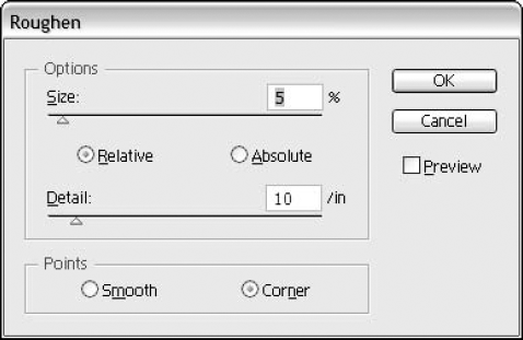
Three options are available:
Size: How far points may move when roughened relative to the width or height (whichever is greater) of the selected path. Choose higher values to increase the apparent roughness.
Detail: How many points are created per inch. Choose higher values to create more points.
Smooth or Corner Points: If you click the Smooth radio button, all the anchor points added are smooth points. If you click the Corner radio button, all the points added are straight corner points. Use Smooth to create soft edges and Corner to create sharp edges.
Roughen never takes away points when roughening a path.
Tip
You can use the Roughen command as a very hip version of the Add Anchor Points command. If the Size text field is set at 0%, the added points are added along the existing path all at once. Instead of going to Add Anchor Points again and again, just try typing a value of 25 in the Detail text field of the Roughen dialog box. You have instant, multiple Add Anchor Points. This technique is great for Tweak (explained later in this chapter) or anything else where you need a bunch of anchor points quickly.
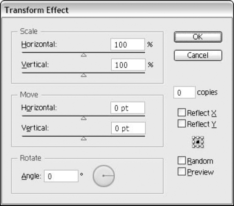
You find the Transform command under the Distort & Transform submenu of the Effect menu. The transform effect is similar to the Transform panel, except that you can go back and edit as well as see the preview before applying.
Choosing Effect

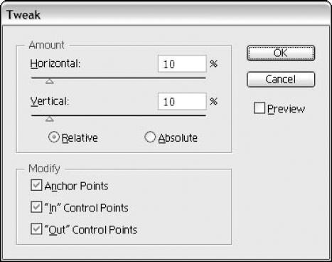
Choosing Tweak opens the Tweak dialog box, as shown in Figure 11.36. In this dialog box, you define the amount of tweaking, including the horizontal and vertical percentages and which points are moved (anchor points, in control points, or out control points). Clicking the Relative radio button applies the effect to the Bounding Box edges of the object. Clicking the Absolute radio button moves the points based on the absolute measurements that you type.
Note
No anchor points are added with the Tweak dialog box.
If you type 0 in either text field, no movement occurs in that direction. Illustrator bases the percentage on the width or height of the shape — whichever is longer. If you click the Anchor Points check box, all anchor points on the selected path move in a random distance corresponding to the amounts set in the Horizontal and Vertical text fields. If you click either the "In" Control Points or the "Out" Control Points check box, those points also move the specified distance. In control points are the points on one side of the anchor point that lead into the path. Out control points are the points on the other side of the anchor point that lead out of the path.
Tip
Consider using the Tweak option when you're not sure of the size of the selected artwork or when you can only determine that you want points moved a certain portion of the whole but can't determine an absolute measurement.
Figure 11.37 shows an object that has the Tweak effect applied with the Relative option chosen (above) and the same values with the Absolute option chosen (below).
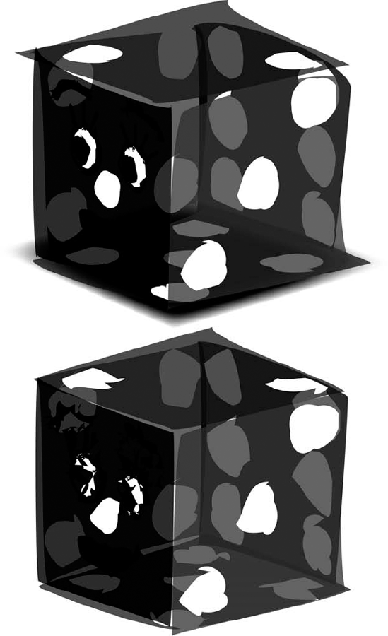
Figure 11.37. The top object was tweaked using the Relative option; the bottom object was tweaked using the Absolute option.
The percentages you type pertain to the Bounding Box dimensions and move points up to those limits. If the Bounding Box is 5 inches wide and 2 inches tall and you type a value of 10% for width and height, the points move randomly up to 0.5 inches horizontally and 0.2 inches vertically in either direction.
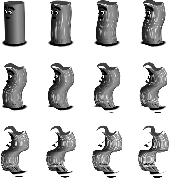
The Twist command is found by choosing Effect
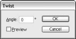
You can twist paths and text (without converting to outlines) to create some really great effects. One of my favorite looks is to take a starburst of lines and twist them into a flower or spirographic shapes using the Twist and Tweak effects, as shown in Figure 11.39. The top-left image has no Twist applied, but a 10° Twist is added to each consecutive image. A positive number twists the object clockwise; a negative number twists the object counterclockwise.
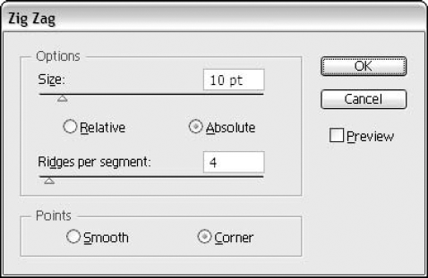
The Zig Zag effect (Effect
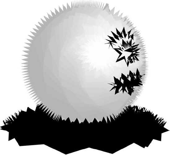
The Zig Zag dialog box allows you to specify various parameters of the Zig Zag effect, including the Size, which is how large each zigzag is, and the Ridges per segment, which is the number of zigzags. In addition, you can specify whether you want the zigzags to be curved (click the Smooth radio button) or pointed (click the Corner radio button). Like most of the other Illustrator effects, Zig Zag has a handy Preview check box. The Relative and Absolute options work just like the similarly named options in the Tweak Effect. Figure 11.41 shows an example of zigzagged artwork.
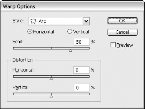
Warp effects are also known as envelopes. Warp effects bend objects into a selected shape. Unlike Free Distort, you have many points to work with and a variety of preset options. You can choose from a variety of predefined warp effects: Arc, Arc Lower, Arc Upper, Arch, Bulge, Shell Lower, Shell Upper, Flag, Wave, Fish, Rise, Fisheye, Inflate, Squeeze, and Twist.
You can find all these warp effects by choosing them from the Effect
In all the preset options, you have Warp Options to edit to your heart's desire. You can set these options:
Style: Pick from 15 predefined warps.
Horizontal or Vertical: This affects either the horizontal areas or the vertical areas of the shape.
Bend: Change how much of an effect is applied in percentage.
Distortion Horizontal: This option allows you to increase or decrease the horizontal distortion in percentage.
Distortion Vertical: This option allows you to increase or decrease the vertical distortion in percentage.
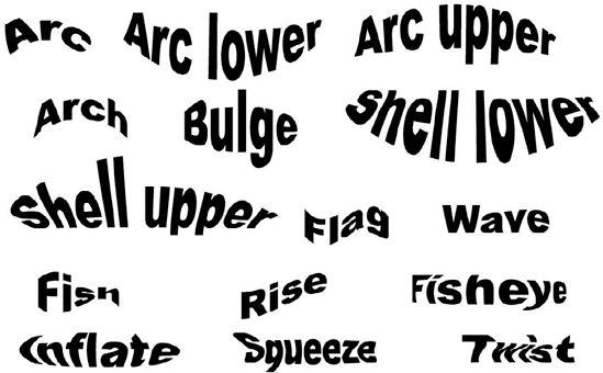
This section provides more information on the 15 Warp Style presets:
Arc: Bends a shape's top and bottom into an arc
Arc Lower: Bends just the lower half of the shape into an arc
Arc Upper: Bends just the upper half of the shape into an arc
Arch: Bends the upper, middle, and lower areas into an arch
Bulge: Pushes out the top and bottom of the shape
Shell Lower: Squeezes in the middle and bulges out the lower area of the shape
Shell Upper: Squeezes in the middle and bulges out the upper area of the shape
Flag: Pushes the shape on the top and bottom into an upper and lower curve
Wave: Pushes the shape on the top, middle, and bottom into an upper and lower curve
Fish: Squeezes the shape into a fish shape
Rise: Pushes the shape upward from lower left to upper right
Fisheye: Bulges out just the center of the shape
Inflate: Bulges out the whole shape instead of just the center
Squeeze: Pushes in the left and right sides of the shape
Twist: Twists the object around the center
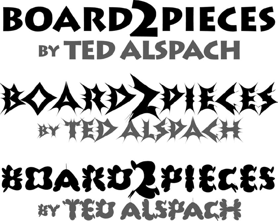
Figure 11.43 shows all 15 presets applied to text.
Distortions and transformations are some of the most fun effects that are built into Illustrator. In this chapter, you learned the following:
You can transform an object multiple ways. You can use the transformation tools, the Transform menu, the Transform panel, or the transform effects.
Add awesome effects by using the Liquify tools in a brush-like fashion.
The Distort effects work by moving points around selected paths.
The Pucker and Bloat features create spiked and bubbled effects, respectively.
Roughen can be used to intelligently add anchor points.
Use either the Twist effect alone or with the Twirl tool to twist artwork.
Twirling adds anchor points as needed when twirling.
Tweak is used to randomly move existing points and control handles.
The Zig Zag effect creates wavy or spiky paths.
Warps push an object into a specific shape.