
21 Active Guideway MAGLEVs
21.1 Introduction
By MAGLEVs we mean here magnetically levitated vehicles:
For high-speed intercity movers
For urban/suburban people movers
For short-haul industrial platforms
Magnetic levitation means controlled suspension and guidance by means of electromagnetic (attraction) or electrodynamic (repulsion) forces. Magnetic levitation may be performed by dedicated dc fed controlled electromagnets—with or without PM assistance—in attraction force MAGLEVs (Chapter 19) or in dc superconducting magnets (or PMs) with air-core active damping coils (Chapter 20). The airgap between the vehicle (platform) and the active guideway has to be dynamically controlled, around rated airgap gm, by ± 25%; gm = 8–10 mm for attraction MAGLEVs and around 100 mm for repulsion force MAGLEVs vehicles. For industrial MAGLEV platforms, the airgap gm could go as low as 1–2 mm.
The propulsion of MAGLEVs is produced with linear electric motors.
For active guideway MAGLEVS [1–5], in general, linear synchronous motors (LSMs) with iron-core (respectively, air-core) three-phase ac windings spread along the entire travel length are used.
In Chapters 7 and 8, the two main active guideway LSMs have been treated in detail:
DC-excited iron-core LSM (active guideway)
DC superconducting air-core LSM (active guideway)
In this chapter, the following items are dealt with:
The structure, principles, and the control essentials of dc-excited iron-core active guide-way LSM attraction force MAGLEV (“Transrapid”)
The structure, principles, and the control of dc-excited LSM air-core guideway repulsive force MAGLEV (“JRM Linear”)
The structure, principles, and the control of PM excited LSM iron-core guideway repulsive force MAGLEV (“General Atomics”)
The various degrees of interaction of propulsive-levitation-guidance functions make the three mentioned active guideway MAGLEVs rather fully representative for people mover applications.
For active guideway industrial platforms, one more solution has been given notable attention: the doubly fed linear induction motor with long (active guideway) iron-core stator and wound mover. The wound mover is, in general, ac controlled at frequency f2 by a partial ratings inverter on board or mover. For heavy starts, the wound mover may be short-circuited and a full-power dedicated on ground inverter (or soft starter) may be used to supply the stator. In view of its potential, this MAGLEV platform will also be offered due treatment in this chapter. Though the subject of this chapter is strongly related to specific industrial solutions, the presentation remains mostly scientific, coherent with the rest of the book. For the sake of self-sufficiency, some reminder knowledge on the linear motors for propulsion and on the magnetic suspension and guidance dc-controlled (or sc) electromagnets is given again in the chapter.

FIGURE 21.1 “Transrapid 08.” (After http://upload.wikimedia.Org/wikipedia/commons/d/d0/Shanghai_Transrapid_002.jpg)
The commercialization in 2002 of the first active guideway MAGLEV people mover (Transrapid, Figure 21.1) with the peak speed of 430 km/h (or more) and the advanced stage of the SC and PM active guideway MAGLEV people mover for 550 km/JRM and 160 km/h (General Atomics), respectively, are based on MAGLEV merits such as
Lower vehicle weight/passenger at given speed
Lower kwh/passenger/km (at given speed) than in high-speed wheel-suspension trains (such as TAGV, etc.)
Notable lower track maintenance costs as the interaction forces with the guideway are distributed over 104 larger areas than in wheeled vehicles
Lower noise and better ride comfort at super high speeds (400-550 km/h)
For active guideway MAGLEV systems, the cost of the active guideway and of the ground inverter stations is said to be compensated at high traffic density by the absence of full power transfer to the vehicle, which is hosting lower power equipment fed from linear generators on board, backed by a storage battery.
21.2 DC-Excited Iron-Core LSM Maglev Vehicles (Transrapid)
The schematics of an active guideway dc-excited iron-core LSM MAGLEV vehicle is shown in Figure 21.2:
The “Transrapid like” system may be characterized as follows:
The T shape guideway sustains, on the lower part, two long iron-core stators with three-phase ac cable windings fed, in synchronized manner, from on ground inverter power substations.
On board, there are two rows of dc-excited poles in iron-core inductors, which make the LSM secondary.
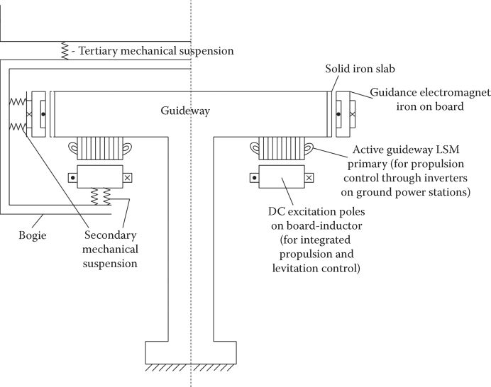
FIGURE 21.2 DC-excited iron-core LSM MAGLEV with active guideway.
The magnetic flux density produced in the airgap by the dc coils (about 0.55–0.65 T) not only produces the stator ac emf, which is about in phase with controlled stator current (iq control), but also produces the fully stable magnetic suspension of the vehicle by advanced robust control of field coil currents (Chapter 7).
To reduce the “unsprung mass,” the dc excitation cores on board are attached to the bogie through a secondary mechanical suspension system; a tertiary (active) mechanical suspension system between the bogie and the passenger cabin provides the required comfort up to maximum speed (430 km/h, so far), for a reasonable dynamic energy consumption (3 W/kg) (Chapter 19).
To reduce the cost of the laminated long stator, open slots (allowed by the large airgap ≈ 10 mm, rated) are filled with a single-layer diametrical aluminum-cable winding with q = 1 slots/pole/phase (Figure 21.3); care is exercised for enough transposition of the elementary conductors in the cable to avoid large skin effect losses at around 200 Hz maximum fundamental frequency (at ≈ 400 km/h).
The pole pitch τ is not much larger than stator stack width, to keep the end-connection winding length, weight, and losses small enough; but also, the stack width has to be limited to reduce the long stator costs (Figure 21.4).
With vector control of LSM and id ≈ 0, the interaction between propulsion and levitation is drastically reduced; a bit of around-zero id control may be used to damp some vehicle oscillations, etc.
The guidance function is handled separately by lateral dc-controlled electromagnets acting “against” a solid vertical iron slab provided in the guideway structure.
The electric energy on board of vehicle, required to supply the inductors and the guidance electromagnetics plus the auxiliaries, is produced by “electromagnetic induction,”—that is contact-less—by inserting small pole-pitch (half the stator slot pitch) multiphase coils in the inductor poles (Figure 21.4).

FIGURE 21.3 Long stator cable three-phase winding per active section, (a) and parts of LSM, (b).
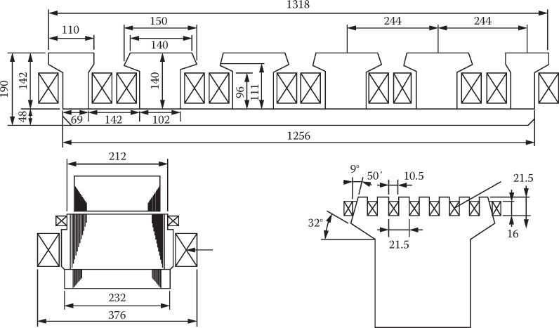
FIGURE 21.4 A practical inductor.
To secure an acceptable propulsion efficiency and power factor (for reasonable inverter kVA ratings (and costs)), the long stator is fed section by section (Figure 21.5) from both ends (to reduce the number of power switches on ground that connect neighboring sections to a power substation) (Figure 21.6).
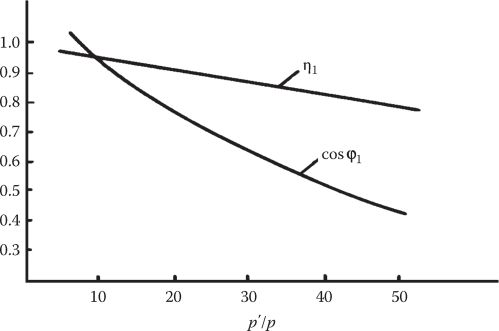
FIGURE 21.5 Typical propulsion efficiency and power factor versus active section length/inductor length (p′/p).

FIGURE 21.6 Generic supply system for Transrapid like systems.
As the electric energy is taken from a typical 10 kV public system, there are quite a few stages of energy conversion to reach the medium voltage level (4–6 kV), typical to a three-level (or more) medium voltage inverter.
A general view with two neighboring power substations is shown in Figure 21.7.
The system complexity is evident; but the formidable performance required by a magnetic flight 8 ÷ 12 mm below the track should also be evident, if we only consider the precision alignment of 1–2 mm per 3 m of stator in length, in order to secure such low height flight at above 400 km/h.
The propulsion is controlled essentially from the ground power substations and vehicle position and many more data have to be transmitted from/to vehicle by a complex radio system, to secure safe rides even in all foreseeable fault conditions.
The control of LSM is basically based on field orientation control (FOC) and, as already mentioned, “pure” iq control could provide minimum propulsion–levitation interference (Figure 21.8). FOC also provides easy regenerative breaking even at very low speeds. If the retrieved breaking energy cannot be sent back to the public power system, a resistor in the dc link may be controlled to dissipate it for a good cause.
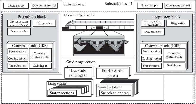
FIGURE 21.7 Typical propulsion structure with supply substations. (After Alscher, H. et al., IEEE Spec., 8, 57, 1984.)

FIGURE 21.8 Pure iq operation of LSM (a) motoring and (b) generating (regenerative braking).
As the flight height is small, no safety wheels are required. But they may be needed to pull a faulty vehicle to the repair shop. Safety skids should be provided. Additional (safety) electric braking may be obtained through the guidance electromagnets, where a convenient ac additional current “insertion” will produce stronger eddy currents in the solid iron slabs in the track, working as an efficient eddy-current brake down to low speeds.
An aerodynamic safety (parachute type) braking system may also be provided.
As levitation robust (variable structure + PI) decentralized airgap dynamic control of each inductor units is used, the propulsion and the vehicle interference are handled as disturbances.
For detailed control of attraction force suspension systems (see Chapter 19), it may be also feasible to control id also around zero in the sense of using it for damping some vertical inductor motion oscillations (not done so far, apparently).
The “Transrapid like” system implies multidimensional motion damping and stabilization; such a complex objective is beyond our scope here.
All in all, capable of less than 70 Wh/passenger/km at 400 km/h cruising speed, the Transrapid system has showed remarkable performance and its extension in very heavy traffic locations, throughout all continents, should be seriously considered.
21.3 Supercon MAGLEVs
By Supercon MAGLEVs, we mean the MAGLEVs with superconducting inductors on board of vehicles (Chapter 20), which handle both levitation and guidance (by, in general, repulsion forces) (Figure 21.9). In some special null-flux configuration with nonoverlapping stator three-phase eight-shape coils (properly connected), propulsion, levitation, and guidance may be handled by the same, though a bit more complex, guideway (stator) coil system.
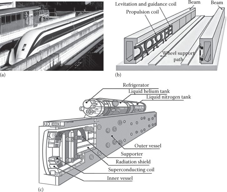
FIGURE 21.9 JR-MLX supercon MAGLEV, (a) general view (after http://ro.wikipedia.org/wiki/Fi%C8%99ier:JR-Maglev-MLX01-901_001.jpg), (b) stator coils distinct propulsion and levitation guidance, and (c) supercon magnet. (After Alscher, H. et al., IEEE Spec., 8, 57, 1984.)
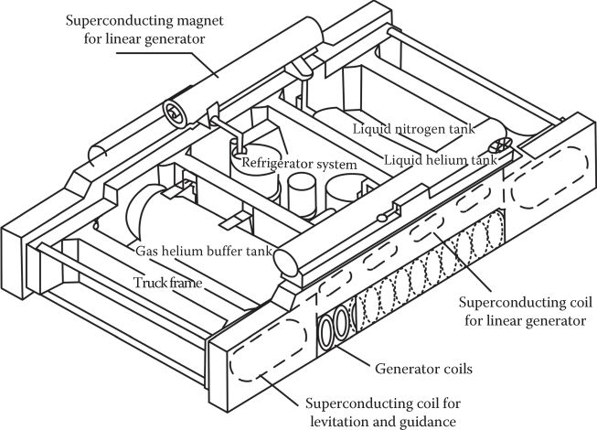
FIGURE 21.10 Generic magnetic bogie of “JL-MLX” MAGLEV. (After Alscher, H. et al., IEEE Spec., 8, 57, 1984.)
The generic magnetic bogie is visible in Figure 21.10.
A detailed view of Supercon magnets (3) and stator propulsion (1) and levitation-guidance figure-eight-shape coils (2) is shown in Figure 21.11.
The key design issue is related to the figure-eight-shape levitation–guidance ground coils, which are connected as in Figure 21.12, which provides for levitation and guidance control.
The separate propulsion coils (Figure 21.11a) constitute a two-layer diametrical ac cable winding, which means a unity winding factor, for a strong interaction with the supercon magnets on board, to produce high propulsion force. To reduce the complexity of a guide-way coil, it seems feasible to use the figure-eight-shape coils as in Figure 21.12, connected longitudinally in a three winding with coil pitch of τ/3 (τ—the supercon magnet pitch). This means a nonoverlapping winding with q = 1/2, which leads to a lower winding factor (0.867) but for great savings in total guideway coils costs (Figure 21.13).
In this case, it may be better to notably increase τ above 1.35 m.
A generic feeding system of propulsion winding section for JR-MLX MAGLE is shown in Figure 21.14. It looks similar to the one for Transrapid, but the power involved is in the range of tens of MVA as the maximum speed is over 560 km/h and the trains are larger (Table 21.1).
For details on the LSM and repulsion force levitation system design and control, please revisit Chapter 20.
Overall, the JR-MLX MAGLEV is the only MAGLEV with tested performance, perhaps at 160 W/passenger/km above 450 km/h (up to 580 km/h). If such speeds are needed, this may be the first choice.
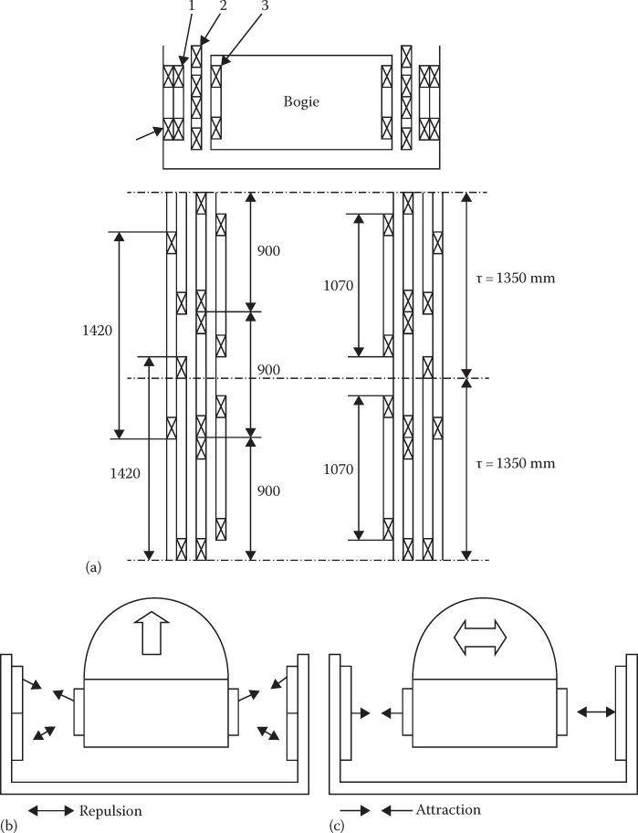
FIGURE 21.11 Supercon magnets on board (3) with propulsion coils (1) and levitation-guidance coils (2) (a) on ground, (b) levitation, and (c) guidance principles.
In contrast with Transrapid, full levitation is reached above a critical speed (50 m/s or more) and thus acceleration on retractable wheels, up to a critical speed, is required.
The large practical airgap of 100 mm allows for higher active track irregularities, for given ride comfort, at given speed. It also simplifies the stabilization of levitation-guidance functions; a control coil placed between the supercon magnets and the figure-eight-shape track coils provides active vertical motion damping at 0.3 W/kg (3 W/kg is required in all for Transrapid controlled levitation).
Regenerative braking is feasible with supercon MAGLEVs also, from on ground inverters’ control.
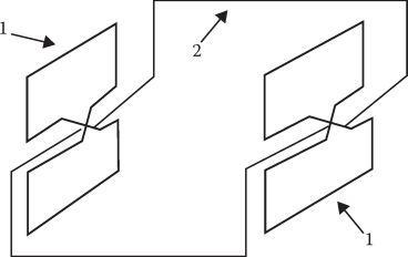
FIGURE 21.12 Null-flux connection of levitation-guidance coils (1, coils; 2, null-flux cable).
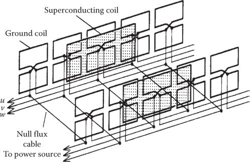
FIGURE 21.13 Integrated propulsion-levitation guidance on ground coils. (After Murai, T. and Fujiwara, S., Trans. IEE Jpn., 116-D, 1289, 1996.)

FIGURE 21.14 Feeding system of propulsion winding sections (JR-MLX).
TABLE 21.1
Specification Data of MLX 01 MAGLEV Trains
The large drag force of levitation–guidance coils on ground at medium and low speeds provides “eddy current” braking but not down to zero speed. The same drag force impedes on vehicle acceleration efficiency, in contrast to Transrapid. Finally, the safety (and during acceleration) wheels may be equipped with disk brakes as done on aircraft, for safety and stop braking.
21.4 Iron-Core Active Guideway Urban PM-LSM MAGLEVs
In an effort to introduce active PM-LSM guideway urban MAGLEVs, with a simplified control, the system in Figure 21.15 was proposed in the last decade by “General Atomics” in the United States [7].
It looks similar to Transrapid in terms of long iron-core stator with cable ac three-phase winding (Figure 21.16), but the stator core is split into two parts to provide practically lateral self-centralization (guidance). This solution may be acceptable for urban transportation purposes, if lateral (safety) rubber wheels are provided.
For levitation, Litz-wire short-circuited coils in a nonmagnetic strong mold are placed along the track as in a repulsive force magnetic suspension system (Chapter 20).
The on-ground levitation coils “see,” in a null-flux configuration, the variation (due to speed) of the magnetic field (Figure 21.15) of dual-PM Halbach array system on board.
The Litz-wire in the levitation coils is used to reduce the skin effect and thus, for given PM Halbach array pole pitching, reduce the critical speed (to 2.5 m/s!) when full levitation at about 25 mm height is obtained.

FIGURE 21.15 Active guideway PM-LSM urban MAGLEV. (After Borowy, B.S. et al., Controller design of linear synchronous motor for General Atomics urban MAGLEV, Record of LDIA-2007, 2007.)
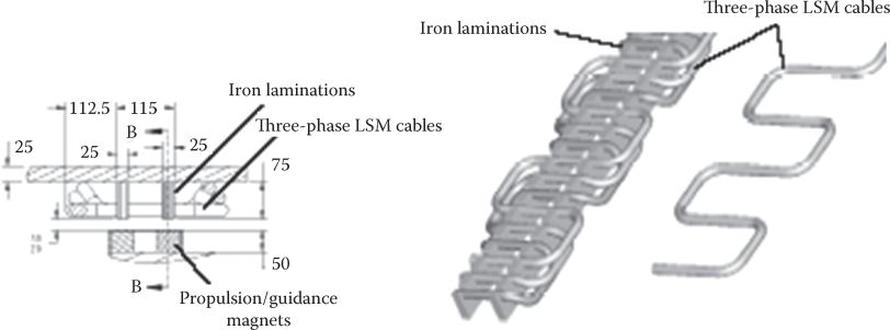
FIGURE 21.16 Three-phase stator LSM winding and propulsion-guidance PM inductor on board. (After Borowy, B.S. et al., Controller design of linear synchronous motor for General Atomics urban MAGLEV, Record of LDIA-2007, 2007.)
The drag force, typical to repulsion force MAGLEVs, is also reduced; it is argued that no dedicated control is required for levitation; some levitation (vertical motion) damping may be performed by the FOC of the LSM, where control is at disposal to modify to some extent the levitation force, produced by the PM inductor of the LSM.
With full-size prototyping on the way (Table 21.2), the system feasibility—technically and commercially—is still to come.
TABLE 21.2
Key System Parameters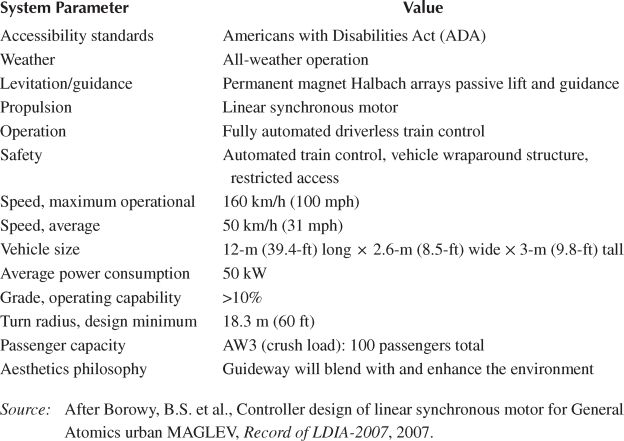
21.5 Active Guideway Multimover Doubly Fed Lim Maglev Industrial Platforms
Though designed for high-speed people movers, the Transrapid MAGLEV may be scaled down to small powers for short-haul industrial platforms. However, because the dc inductor on board works at zero frequency, a long stator section can control just one vehicle. There are applications where, within one energized section (say without an inverter but with a soft starter supply) we should handle a few movers independently and/or in a synchronized convoy. As in such applications the airgap may be reduced to 1–3 mm for up to tens of meters of travel, the doubly fed LIM may be the way to go, to provide integrated propulsion–levitation field-oriented control.
An exemplary arrangement with two long stator sections and two movers (secondaries) is visible in Figure 21.17 [8], and it may be modeled as in Figure 21.18.
Now the two stator sections interact with both movers. This is a special situation; apparently, in such an extreme situation only convoy motion mode, same speed, of the movers is feasible. In most cases, however, we may consider two or more movers in the same stator section, which may travel at different speeds or in a convoy (same speed). The slip frequency of the two movers f2A and f2B are

FIGURE 21.17 Coupling inductances with two three-phase stator sections and two three-phase movers in the neighborhood (doubly fed LIM). (After Henke, M. and Grotstollen, H., Control of linear drive test standard for MBP railway carriage, Record of LDIA-2001, Nagano, Japan, 2001.)

FIGURE 21.18 Equivalent circuit of the arrangement in Figure 21.17. (After Henke, M. and Grotstollen, H., Control of linear drive test standard for MBP railway carriage, Record of LDIA-2001, Nagano, Japan, 2001.)

FIGURE 21.19 Field-oriented propulsion control of two secondary doubly fed LIM platform. (After Henke, M. and Grotstollen, H., Control of linear drive test standard for MBP railway carriage, Record of LDIA-2001, Nagano, Japan, 2001.)

FIGURE 21.20 Speed (m/s), position (m), iL1q (A), VL1q (V) in acceleration-deceleration experiments. (After Henke, M. and Grotstollen, H., Control of linear drive test standard for MBP railway carriage, Record of LDIA-2001, Nagano, Japan, 2001.)
Now distinct field-oriented propulsion control of the two three-phase wound movers A and B may be applied (Figure 22.19). A master and slave control system might be more appropriate [8].
Independent propulsion control of the two movers (not done yet) within a single stator section can be obtained by separate speed close-loop control in Figure 21.19 (after changes). For MAGLEV operation, the movers have to be placed below the stator section as there are attraction forces between the stator and movers. As the airgap is small, the airgap flux density may be 0.6–0.7 T, and thus enough attraction force can be produced. Thus suspension control—based on airgap and current robust control—can be produced Figure 21.19. Typical low-speed propulsion performance for convoy (same speed) lab operation is shown in Figure 21.20 [8].
Even position-sensorless controlled propulsion has been demonstrated. For lower cost, the stator inverter might be replaced by a soft starter, when, for heavy starts (if needed), the mover three-phase winding can be temporarily short-circuited. With a battery on board of mover, even its recharge (or s.o.c. control) can be orchestrated.
21.6 Summary
Active guideway MAGLEVs refer to people movers and industrial platforms with magnetic suspension, guidance, and propulsion by long stator (guideway) linear electric motors [9–11].
Iron-core (Transrapid) or air-core (“JR-MLX”) three-phase cable windings may be used in the long (active guideway) stators.
To constitute linear synchronous motor propulsion, the vehicles host dc inductors with controlled electromagnets or dc-superconducting magnets (JR-MLX).
The Transrapid system, already commercial since 2002, provides 8–12 mm controlled airgap magnetic flight up to 430 km/h, while the “JR-MLX” system has been proven full-scale performance providing 80–120 mm height controlled airgap flight up to 580 km/h.
The energy consumption for Transrapid is about 60 Wh/seat/km at cruising speed of 400 km/h while it is more than 150 Wh/seat/km for “JR-MLX” at 580 km/h cruising speed. Both values should be considered very good in comparison with high-speed bullet trains (TAGV, etc.) or airplanes for same door to door travel time.
As Transrapid shows a small airgap and is based on attraction force levitation guidance, the control system should be stabilizing the vehicle both statically and dynamically. For the “JR-MLX” MAGLEV, mainly dynamic stabilization is required.
Both systems allow for regenerative braking by propulsion control initiated in the on-ground inverter power substations.
As vehicles experience multidimensional motion, their stabilization and providing good riding comfort is a daunting task; apparently, it has been solved for both Transrapid and “JR-MLX” MAGLEVs [11].
For urban MAGLEVs, the SC magnet inductors may be replaced by PMs on board; a null-flux repulsive force levitation system, with dual PM rows on board and short-circuited air-core coils on ground, has been added and thus the “General Atomics” system has been completed. It claims no need for levitation and guidance control, while the ride comfort is provided by mechanical suspension systems. The propulsion system and its control are as for Transrapid systems. The system is yet to be full-scale tested.
For MAGLEV industrial platforms, the Transrapid system may be scaled down adding PMs in the inductor poles. “Zero power” levitation control may be applied by allowing the airgap to vary within some large (but safe) limits; beyond this airgap, safety (collision avoidance) control is performed.
In addition, for MAGLEV platforms, but even for urban MAGLEV vehicles, the doubly fed LIM for propulsion and levitation can be used. The three-phase winding on board can handle, in interaction with a three-phase iron-core long stator, both propulsion and levitation control. The system may control even two vehicles independently, on a long enough active stator section, by controlling the on-board mover inverters at different slip frequencies f2A and f2B. For dc control in the mover windings, the system “degenerates” into Transrapid situation.
Stator coil and PM-mover small MAGLEV platforms have been investigated in Chapter 18, dedicated to planar motor LOMs.
References
1. H. Weh, Synchronous long stator motor with controlled normal force, ETZ.A-46, 1975 (in German), 409–413.
2. K. Meinrich and R. Kretzschmar, Transrapid Maglev System, Hestra Verlag, Darmstadt, Germany, 1989.
3. H. Kolm, R.D. Thornton, Y. Iwasa, and W. Brown, The magniplane system, Cryogenics, July 1975, 377–383.
4. E. Ohme, M. Iwamata, and T. Yamada, Characteristics of superconductive suspension and propulsion for high speed trains, Proc. IEEE, 61(405), 1973, 579–586.
5. M. Toshiaki and F. Shunsuke, Design of coil specifications in EDS Maglev using an optimization program, Record of LDIA-1998, Tokyo, Japan, pp. 343–346.
6. T. Murai and S. Fujiwara, Characteristics of combined propulsion, levitation and guidance system with asymmetric figure between upper and lower coils in EDS, Trans. IEE Jpn., 116-D, 1996, 1289–1296.
7. B.S. Borowy, H. Gurol, and J.-K. Kim, Controller design of linear synchronous motor for General Atomics urban MAGLEV, Record of LDIA-2007.
8. M. Henke and H. Grotstollen, Control of linear drive test standard for MBP railway carriage, Record of LDIA-2001, Nagano, Japan.
9. M. Mihalachi and P. Mutschler, Capacitive sensors for position acquisition of linear drives between passive vehicles, Record of OPTIM-2010, 673–680.
10. H. Alscher, I. Boldea, A.R. Eastham, and M. Iguchi, Propelling passengers faster than speeding bullet, IEEE Spectrum, 8, 1984, 57–64.
11. D.M. Rate, Review of dynamic stability of repulsive force MAGLEV suspension system, IEEE Trans., Mag-38(2), 2002, 1383–1390.
12. http://upload.wikimedia.org/wikipedia/commons/d/d0/Shanghai_Transrapid_002.jpg
13. http://ro.wikipedia.org/wiki/Fi%C8%99ier:JR-Maglev-MLX01-901_001.jpg