
7 DC-Excited Linear Synchronous Motors (DCE-LSM)
Steady State, Design, Transients, and Control
7.1 Introduction and Topologies
DC-excited linear synchronous motors (DCE-LSM) in flat active ac stator (Figure 7.1) configuration [1–3] are favored for MAGLEVs in low, medium, and high-speed active guideway applications because
They provide, by multiple on board dc exciters, suspension control.
They produce, by interaction of dc exciters on board field and ac-fed long primary (stator) active guideways, MAGLEV propulsion.
The propulsion and suspension functions may be decoupled essentially by pure iq vector control in the ac stators fed by inverters placed on ground, along the track, and synchronized with the vehicle motion.
The propulsion efficiency is reasonable, above 0.75 for 1–1.5 km long active stator sections; power factor is 0.55–0.6 (lagging) for the same conditions.
The suspension power (consumed in the dc exciters on board) is around 3 kVA/ton for an airgap of about 10 mm, which is quite acceptable.
The stator has a laminated core with open slots and q = 1, single-layer, aluminum cable three-phase windings.
There is no power collection system because the active guideway is supplied on ground and because the needed power on board is produced there through dedicated coils on dc exciter poles, which collect the mmf space harmonics field energy of the stator, representing a linear electric generator on board.
Single-sided configurations are favored for MAGLEVs, but double-sided ones may be used when zero normal force is needed in the application.
The PMs (in Figure 7.1b) are used to produce the bulk of the excitation field (say to cover the magnetic suspension of empty vehicle weight), while the dc coils are used only for controlling the static and dynamic stability of magnetic suspension. If all the dc control coils are connected through dc–dc converters from a common dc power bus, the average control power is very low (ideally zero) because of the multiple dc coil energy exchange.
Both the dc exciter mover and the primary (guideway) iron cores are made of laminated silicon steel, while the dc coils are made of copper (or aluminum). Multiphase ac windings of the stator are made of aluminum cables to reduce the initial system costs. Considered too expensive decades ago, the inclusion of PMs in the dc exciter mover seems today much more practical, especially because of the lower total average power in the control coils.
The ac wound primary guideway is placed on both sides of the vehicle (Figure 7.1a) with the dc exciters below the former, to provide laterally balanced suspension.
The active guideway comprises a silicon-laminated magnetic core with uniform open slots (Figure 7.2). The core is made of sections, 1–1.2 km long, fixed to the track structure.
The single-turn-cable single-layer winding has three slots/pole (q = 1). The premade (preinsulated) cable, one per winding section (1000–1200 m or more), is easy to insert and leads to the reduction of one of two ends of a standard winding coil (per pole pitch). Thus, the aluminum weight, cost, and Joule losses are reduced by about 20%.
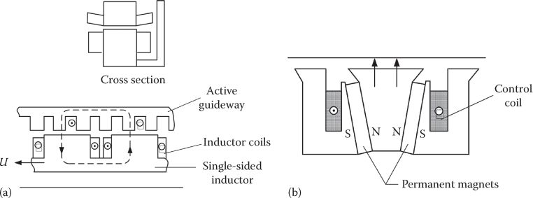
FIGURE 7.1 DCE-LSM with active guideway (stator): (a) with dc excitation on mover; (b) hybrid (dc + PM) mover. (After Boldea, I. and Nasar, S.A., Linear Motion Electromagnetic Systems, John Wiley, New York, 1985.)

FIGURE 7.2 Three-phase armature winding (a) phase slot allocation; (b) cable winding. (After Boldea, I. and Nasar, S.A., Linear Motion Electromagnetic Systems, John Wiley, New York, 1985.)
7.2 DC Exciter (Inductor) Design Guidelines
A typical dc exciter mover module for MAGLEVs is shown in Figure 7.3.
It contains four full-poles and two half-poles at the two ends and is about 1.3 m long, to allow the manufacture of the magnetic core of thin laminations from one sheet piece. To avoid notable lateral forces, when lateral displacement of dc exciter versus stator occurs, the width of the stator stack is slightly shorter than the width of the former.
Also, to harvest energy on board of mover (vehicle), a two-phase ac winding is placed in dedicated slots on the dc exciter poles. Two-phase tooth-wound coils on the dc exciter poles “collect” by electromagnetic induction the mmf open-slot stator harmonics energy. So, a linear generator on dc exciter pole pitch (slot pitch) τs2 = τs1/2 is obtained, τs1—stator slot pitch.
The double slotting on stator and on mover—for an airgap of 10–12 mm in MAGLEVs—produces magnetic flux density harmonics that cause thrust and normal pulsations, which, by careful design, may be kept to a reasonable p.u. level, in order to prevent strong vibrations and noise of DCE-LSM.

FIGURE 7.3 Typical dc exciter (inductor) module of DCE-LSM (tentative dimensions in millimeters). (After Boldea, I. and Nasar, S.A., Linear Motion Electromagnetic Systems, John Wiley, New York, 1985.)
The coordination of stator and dc exciter slot opening and the dc exciter pole shoe per pole pitch ratio τp2/τ ≈ 2/3 produces pulsations below 3% in thrust and 1% in the normal force [5].
For preliminary design of the dc exciter, we may suppose that the contribution of the stator mmf field to the normal force is neglected. Such an approximation becomes acceptable if the propulsion control is built around pure Iq control (q axis current in the dq orthogonal model of LSM); the dc excitation field is aligned with axis d. Also, the armature reaction field is notably smaller than the dc excitation airgap field.
The normal force Fn is the attraction force between the dc exciter and the stator core.
The average airgap flux density, Bfg, produced by the dc exciter, is
where
wf is the number of turns per pole (coil)
If is the field current
Kc is the Carter coefficient (see Chapter 2)
Ksat is the saturation factor (includes the influence of the magnetic core to the equivalent magnetic airgap)
The normal force for τp2/τ ≈ 2/3 is
The vehicle weight/meter length Ge ≈ (1.5 – 2.0) ×104 N/m, that is, 1.5–2 ton/m. If the dc exciters cover, on both sides of the vehicle, half the vehicle length, it means that Ge is
The airgap flux density produced by the dc exciter for Ge in the range mentioned here is Bf ≈ 0.5 – 0.7 T. This rather moderate value is motivated by the open slots on both stator and dc exciter poles and serves to avoid heavy saturation of stator and mover core teeth.
With
For lower values of Bf, larger stack width is required. Wider stator stack would lead to better aluminum utilization for given pole pitch (due to relatively shorter “end coils”) but, still, the cost of stator will increase.
There is another factor in the design that is important: speed. For high speeds, in the range of 90–110 m/s, the inverter frequency should not surpass 250 Hz, even with most recently proposed IGCTs—voltage source inverters (switching frequency up to 2–3 kHz), if a rather sinusoidal current (field-oriented) control is to be applied for propulsion.
For f1 = 250 Hz and 110 m/s, the stator and the mover pole pitch τ is
Though lstack/τ ratio may be smaller than unity, the solution is acceptable as the cable winding eliminates one of two end connections (Figure 7.2b), while the cost of the active stator core is reduced with shorter stack width (lstack/τ ≈ 0.6–0.8).
For smaller speeds, the pole pitch will be decreased, but not proportionally, as still considerable room is needed per dc exciter pole to produce the 0.5–0.75 T airgap flux density, unless the airgap is decreased notably for low speeds.
The dc exciter mmf per pole wfIf, for g = 10 mm, Bfg = 0.65 T, and Kc = 1.2, Ksat = 0.2, is (7.1)
For a fill factor Kfill = 0.45 and jco2r = 3.5 × 10⁶ A/m2, the required window area per pole (coil) Awin is
The space available for the dc excitation coils in the typical dc exciter is quite acceptable for ac coil width of 50 mm and a height of 112 m.
For dynamic control of magnetic suspension, higher wf maxIfmax is required, but not above 4.4 A/mm2 and thus the cooling of the dc exciter may be provided (most probably) by the air flow around it (resulted from the motion of the vehicle).
The dc exciter back-iron depth hy2 is
So the 0.048 m available in Figure 7.3 will allow even 1.0 T in the back iron, besides space left for eventual bolts for framing.
The dc exciter module is supposed to be supplied separately from a voltage source of Vdc = 220 V. To allow room for fast field current variation in order to stabilize the magnetic suspension, a 5/1 voltage boost is allowed here. Consequently, the rated dc voltage of the dc exciter is
With RF, the dc exciter module resistance is
so
Consequently
with lstack ≈ 0.2 m; lcoF dc exciter turn length is
or
The field rated current IFr yields
The copper total cross section area per turn ACo is thus
As the ac field current components will add to the steady-state dc component, to provide dynamic suspension stability, the dc exciter coils may be made of copper foils, after careful assessment of the skin effect on total copper losses.
The steady-state power for suspension is (in W/kg)
For the 5/1 voltage boost, the peak kVA of the dc exciter pole dc–dc converter will be about Psus × 5 ≈ 3 kVA. This is quite a small value in comparison with the true propulsion requirements, as seen later.
7.3 Stator (Armature) Core Design
With the pole τ and the stack length (average value for stator and dc exciter) already in place, and q = 1 slot/pole/phase, the main question is related to the mmf per phase required to produce the peak thrust w1I1peak and the number of turns w1 per phase, for given dc supply power station on ground and inverter voltage, at cruising/maximum speed.
Let us consider the peak acceleration apeak = 1 m/s2 (to observe adequate passenger comfort) available up to 40 m/s, for a maximum speed usmax = 110 m/s; the aerodynamic drag adds at 40 m/s only 5%–6% to the accelerating thrust, and the thrust at maximum speed is 40% of the peak thrust.
Let us also consider 2 ton weight per vehicle meter length.
So the peak thrust occurs (Figure 7.4) at 40 m/s; this may be considered the base speed of the drive.
With pure Iq control (Figure 7.4), the phase current is in phase with emf E1 (to decouple suspension from propulsion function):
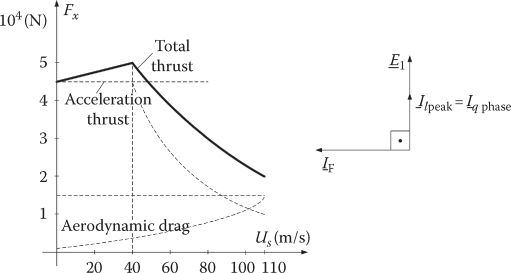
FIGURE 7.4 Thrust/speed for a 45 ton MAGLEV at 110 m/s.
With 2 ton per vehicle meter length, there is 22.5 m for the length of a 45 ton vehicle. The peak thrust per 1 m of vehicle length is thus
As the dc exciters occupy half of the vehicle length on the left and right side, the situation is equivalent to one side with a continuous dc exciter module row. But for 1 m length of vehicle, there are about five stator poles (τ = 0.22 m), and thus, the number of equivalent turns per phase w1 is (single-layer windings)
The number 2 (not 5/2) was chosen for design safety.
Let us note that there is one bar (cable) per coil and one coil per pole per phase.
From (7.19) to (7.21), we find w1meterI1peak:
So the number of peak A turns per slot is Ipeak
Again, with a fill factor of Kfill = 0.27 (cable winding) and jCo1p = 4 A/mm2 (aluminum cable, short duty cycle), the slot area Aslot1 is
With a slot pitch τs1 = τ/3 = 0.22/3 = 0.0733 m and a tooth wt1 = 0.03 m, the slot width is ws1 = τs1 − wt1 = 0.0433 m. So the slot height hs1 is
This leads to a rather small slot aspect ratio hs1/ws1 = 34.00/43.3 = 0.786, which, in turn, means a low slot leakage inductance of stator winding; thus, an acceptable power factor (and converter kVA) can be expected, as 1–1.5 km sections of primary are connected on both sides of the vehicle at any time.
But if the aluminum Joule losses are too large, a smaller current density is adopted, and thus, the primary slot becomes deeper, and consequently, the slot leakage inductance becomes larger. So the power factor decreases and the converter kVA rating increases.
An optimum problem is implicit here, but this is beyond our scope to follow it up further.
7.4 DCE-LSM Parameters and Performance
Let us now consider the case of a DCE-LSM with 2p poles per vehicle length for 2p′ > 2p poles per stator active section length.
Also, on each side of the vehicle, only half of the poles are active (because only half of the length is occupied by dc exciter movers).
Furthermore, we may assume that the active track (stator sections) on the two sides of the vehicle is supplied by separate inverters on ground, to damp eventual transverse vertical axis motions of the vehicle.
The parameters to consider here are the emf per phase E1, the stator active section resistance R1, leakage inductance La1, and synchronous magnetization inductances Ldm, Lqm, all needed for performance evaluation through the phasor diagram in steady state and then for dynamics modeling and control.
The emf E1 (per phase section length, per vehicle side) is (single layer, cable winding, q = 1)
The stator active section resistance (per vehicle side) R1 is
The magnetization inductances are straightforward in approximated expressions [6]
with
With
As the airgap is rather large, more precise values of Ldm, Lqm that include slot opening and magnetic saturation influences, may be derived from FEM investigations.
The leakage inductance per phase per side per active section La1 contains three terms: one corresponding to the part occupied by the dc exciters La, one slot and end-connection leakage inductance of primary part free of the dc exciters Las, and one corresponding to the field below the “empty” stator section (unoccupied by the dc exciters), Les:
La is straightforward [6]:
In (7.36), the distribution of the field below the “empty” stator was considered to correspond to a large airgap (τ/π), which, for a 2D field analysis, is acceptable (3D FEM analysis may be used for even better precision).
The efficiency η1 and the power factor cos φ1 may now be defined for an active section (and one vehicle side):
where pirona represents the core losses in the active part of the stator that faces the dc exciter (where the flux density is large in iron) and pironp represents the core losses in the “empty” part of slots, (p′−p/2)τ in length, where the flux density in iron is small but the iron weight is very large. Again, the propulsion force Fx is
For the control, the relationship between If and emf E1 is to be expressed in terms of mutual (motion) inductance MaF:
In terms of the dq orthogonal model, the thrust may be expressed, in general, by the formula
Park transformation writes (in mover coordinates)
where
The presence of the homopolar components is related to the possible presence of the Δ connection of phases, to allow section feeding from both ends, with simplified power switching devices.
Also, the synchronous inductances Ld, Lq are
It should be noticed that La1 ≈ Ldm or Lqm because the “empty” part of the active primary section is much longer than the one “covered” by the dc exciters on board of vehicle (mover).
To complete the steady-state general analysis motoring and generating, phasor diagrams are given in Figure 7.5, for pure Iq control or zero phase lag between emf and stator current in each phase.
It might be argued that this way the reluctance thrust is not used (Id = 0); true, but, Ld/Lq ≈ 1, and, instead, notable decoupling of propulsion and suspension function is obtained, except for the cross-coupling saturation effect, which is small because the airgap field-current-produced flux density is reasonably low (0.65 T) and the stator peak mmf reaction airgap flux density is less than 0.15 T in general.
Generating mode is required for vehicle (mover) regenerative braking, provided the converter that feeds the active stator section can handle (retrieve) the recuperated energy.
It is evident that, with pure Iq control, the DCE-LSM is always underexcited, which, however, allows easily regenerative braking through a bidirectional dual-voltage source converter.
Typical efficiency and power factor performance, obtained for the case study in the design performed earlier in this chapter, are shown in Figure 7.6.
Though the results are orientative, it is clear that, to secure good performance, the active section length to vehicle length ratio (p′/p)—where only half of the vehicle length is covered by the dc exciters on the mover—should not be above 25–100. For a 50 m long vehicle of 100 ton, this would mean 1.25 km of active track sections; the latter is traveled (at 110 m/s) in roughly 11 s.

FIGURE 7.5 Phasor diagrams of DCE-LSM: (a) motoring, (b) generating.

FIGURE 7.6 Typical efficiency η1 and power factor cos φ1 of a DCE-LSM 45 ton MAGLEV at 110 m/s.
As some sections supply overlapping is necessary at active section switching, there is enough time to achieve seamless transition of vehicle from one active section to another.
7.5 Circuit Model for Transients and Control
The circuit model for transients and control stems from the rotary synchronous machine orthogonal model with pertinent adaptations (per vehicle side):
In the absence of a secondary suspension system,
M is the vehicle mass (M/2 corresponds to one vehicle side served by one inverter for one active stator section). If magnetic suspension is not used, Equation 7.45 is not needed (or controlled).
Note: When a secondary (mechanical) active or passive suspension is used, besides the primary magnetic suspension, more equations are added. Also separate equations for each group of dc exciters that are controlled from same source, if this is the case, are to be used with track irregularities accounted for, to allow for ride comfort assessment (as shown in later chapters, dedicated to magnetic suspension and MAGLEVs).
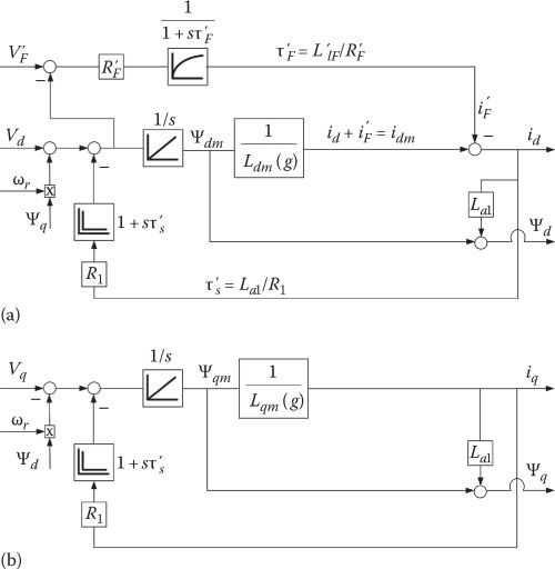
FIGURE 7.7 Structural diagram of DCE-LSM at given speed ωr (a) axis d; (b) axis q.
Model linearization may be used to investigate stability under various controls but, due to strong nonlinearities in the system and large variation of variables, robust control systems are needed for DCE-LSM.
A structural diagram of DCE-LSM equations is shown in Figure 7.7 to serve in the control system analysis and design. As shown, for id = 0, the structural diagram is notably simplified because no damper cage is present and the influence of the linear generator placed on the pole shoes of the dc exciter is not considered.
Only the stator leakage and dc exciter leakage time constants are present. By extracting power from stator mmf harmonics field, the linear generator placed on the dc exciter pole shoes does not interfere directly with the structural diagram that depicts space fundamental properties of the machine.
The equations of motion, horizontal (propulsion) and vertical (suspension, in (7.44) and (7.45)), may be added in a separate structural diagram (Figure 7.8).
If a secondary (and tertiary) suspension was used, the vertical motion structural diagram (Figure 7.8b) would include their pertinent equations. Only for zero id, approximately, the normal force Fn is
Magnetic saturation is neglected due to the large airgap and for simplicity, but the Ldm, Lqm dependence on airgap, which varies notably in MAGLEVs (say, from 20 to 10 mm), is visible all over in the structural diagrams; track irregularities may also be included as they further modify the airgap, but this is beyond our scope here. Though nonzero id is considered in the structural diagrams in Figure 7.7a and b, zero id current control is targeted to decouple the propulsion and suspension functions in the control system.

FIGURE 7.8 Motion structural diagrams of DCE-LSM/vehicle side: (a) propulsion and (b) vertical (suspension) motion (id = 0 in normal force Fn).
7.6 Field-Oriented Control of DCE-LSM
The zero id field-oriented control (FOC) of DCE-LSM is similar to that of rotary SMs, but the field current may be handled differently:
With given versus speed dependence when suspension control is absent (eventually to provide maximum thrust).
With the controlled to keep the airgap versus time g*(t) as commanded by the suspension system central control. Each dc exciter module (or group of them) is controlled to satisfy magnetic suspension performance and ride comfort in MAGLEVs.
A typical FOC system is shown in Figure 7.9.
While Figure 7.9 treats the case of both propulsion and suspension decoupled control, in the absence of suspension control, the reference current (in Figure 7.9b) is given based on dedicated objectives such as versus speed envelope or operation at unity power factor, etc.
The emf decoupling (in Figure 7.9a) is introduced to improve the control at high speeds and allow open-loop space vector PWM in the converter, to exploit best the limited switching frequency to maximum fundamental frequency rather small ratio at high speeds, even when multilevel inverters are used on ground to supply the vehicle.
The measured variables are, in general, mover position θer (used to calculate speed U = (dθer/dt)(τ/π)), stator currents ia, ib, and dc field current iF (the field current reduced to stator is used in the control); moreover, for suspension control, the airgap g is measured (perhaps also the vertical acceleration should be measured, by inertial accelerometers) to provide a robust vertical speed observer used for a second-order sliding mode (SM) functional. SM stands for sliding mode control, a very robust and practical control strategy [7].
Alternatively, direct stator flux and thrust control (DTFC) can be applied instead of FOC, but the zeroing of id current, to reduce propulsion-suspension interaction, may render the later as more practical.

FIGURE 7.9 General FOC of DCE-LSM: (a) propulsion FOC control for zero id and (b) decoupled airgap (suspension) control.
7.7 Note on PM + DCE-LSM
For the PM + dc coils exciters, the design [8] model for transients and control is very similar but
The electromagnetic airgap in axis d is increased by the presence of PMs, so Ldm becomes smaller than Lqm and MaF also becomes smaller.
The flux in axis d gets an additional component
The normal force Fn (per vehicle side or 50% mover occupancy) formula gets a new expression to include the PM contributions:
The main advantages of hybrid (PM + dc exciters) for LSM are excitation power reduction and low total suspension control power for MAGLEVs.
At the limit, if the field coils are eliminated from the dc exciter (mover) and replaced by PMs, still the developments in this chapter can be adapted to the situation, but, for integral suspension–propulsion control, DTFC may be used (zero id current control is not good anymore) with stator flux control for propulsion control and thrust control for suspension control.
7.8 Summary
DCE-LSM means dc-excited linear synchronous motor with short dc exciter mover and long ac-fed stator along the track (excursion length).
DCE-LSM may be applied for short travel (a few meters) transport on linear bearings or on magnetic suspension (MAGLEVs) or to medium or high-speed MAGLEVs.
The dc exciter (mover) contains a heteropolar concentrated dc coil magnetic laminated core, which produces by motion a traveling magnetic field in the airgap at the linear speed us and pole pitch τ; a four full-pole and two end-pole configuration produces a well-behaved heteropolar airgap magnetic field distribution that allows minimum back-iron thickness (weight).
The dc exciter full poles contain a few slots (say, 6) to host a two-phase winding with tooth-wound coils and a pole pitch τ2 = τs1/2; τs1—slot pole pitch in the three-phase ac-fed primary stator. A linear electric generator (LEG) that collects the power by electromagnetic induction, from the stator mmf and slot harmonics, is thus obtained; the LEG produces enough energy, above a certain speed, to recharge the backup battery on board of mover and supply the dc excitation circuit to provide LSM dc heteropolar excitation and (if applied) controlled magnetic suspension (in MAGLEVs).
A basic design methodology for dc exciter is put into place for an initial 110 m/s, 2 ton/m length MAGLEV, propulsion and suspension system.
The airgap flux density by dc exciter is chosen in the interval of 0.5–0.7 T, the maximum frequency in the stator f1max = 250 Hz, and thus, the pole pitch τ for usmax = 110 m/s is τ = 0.22 m; the stack length is chosen as lstack = 0.2 m and thus occupying half of vehicle length on each side, for a MAGLEV of 2 ton/m and an average airgap of 10 mm, only 0.62 W/kg is needed for suspension of the vehicle. For dynamic airgap control, via field current control, a 5/1 over voltage is provided in the dc supply on board (from 44Vdc to 220Vdc); we end up with 3 kVA/ton peak rating of the dc–dc converter that feeds the field circuit.
Though the dc exciter design methodology was exercised on a high-speed MAGLEV, it may be directly applied to a low-speed application as well.
The ac long stator contains a three-phase aluminum cable winding with q = 1 slot/pole/phase and a single layer; this way, a low-cost, easy to install in open slots, solution is obtained; the laminated core along the track length has uniform open slots that house the three-phase ac winding (one on each side of the vehicle in a MAGLEV, for balanced integrated suspension propulsion). Small slot height/slot width ratio is obtained to secure small leakage slot inductance. As an active stator section is more than 1 km long (for a high-speed MAGLEV), this is an asset, in limiting total machine inductance, and provides not so bad a power factor, thus limiting the on-ground converter kVA rating (costs).
2(3)D-FEM or magnetic circuit or multilayer [9] analytical field theory may be applied to calculate rather precisely thrust and normal force.
To decouple the propulsion from suspension, the pure iq vector control of propulsion is adopted for the active stator section. The stator mmf for maximum thrust per slot is thus calculated easily (emf in phase with ac current).
The circuit model parameters of DCE-LSM are calculated observing the “busy” and the “empty” or idle part of active stator section inductances and resistances. Finally R1, Ld, Lq, E1, Ldm, Lqm, MaF are given design expressions, starting from rotary SM theory.
Efficiency, power factor, thrust, and normal force are calculated based on these parameters, for our case study; efficiency in the range of 80% and a power factor of 0.5–0.6 (lagging) is obtained 2p′/2p = 25, with 2p active stator poles and 2p′ active stator section poles. At 110 m/s, 2 ton/m vehicle, 11 s is required for a 50 m long vehicle to travel over a 1.25 km active stator section; this is enough time to switch on and off successive stator sectors with the vehicle in synchronism.
The dq model of SMs is adopted here for the study of transients and control, and dq structural diagrams become rather simplified in the absence of damper windings on mover and at zero id (id = 0).
Separate structural diagrams are added for horizontal (propulsion) motion and for vertical (suspension) motion equations. Airgap variation during suspension control in the presence of track (stator) irregularities is paramount in leading to a heavily nonlinear system. The system may be linearized, but if g varies widely (in 2/1 ratio for MAGLEVs), a robust suspension and propulsion coordinated control is required for stable and high-quality performance of both propulsion and suspension.
For the DCE-LSM control, FOC is proposed; with for decoupled propulsion and levitation, is given by the output of the speed regulator; emf compensation is added to (id, iq) close-loop controllers, and open-loop PWM is performed in the limited switching frequency inverters located in on-ground stations.
The airgap (suspension) control is operated through field current and normal force control; as variation leads also to propulsion force variation, the speed and airgap (suspension) control have to be harmonized for safe and comfortable rides.
If active magnetic suspension is not provided, the field reference current function (versus speed or thrust) is given by an alternative energy conversion criterion.
To reduce the excitation power and the dynamic control power of magnetic suspension, PMs may be added to the dc coils; the so-called “zero control power” principle may be used when all dc exciters with rather average airgap control, in groups, are fed from the same dc power bus on board; the motions of vehicle are damped reciprocally to reach almost zero net average suspension control power, if the PMs provide compensation for all vehicle weight.
At the limit, the dc coils on mover may be eliminated when PMs remain alone; this case will be treated in a separate chapter on LPMSM as it has many new peculiarities for short travel (low speed), medium- or high-speed applications.
As the only commercial high-speed MAGLEV so far uses DCE-LSMs for integrated propulsion- suspension (lateral guidance is provided by dedicated controlled dc electromagnets), the DCE-LSM technologies are expected to develop further in the near future with more application sites in view. More information on active magnetic suspension control and MAGLEVs will be available in later dedicated chapters of this book.
References
1. H. Weh, The integration of functions of magnetic levitation and propulsion (in German), ETZ. A., 96(9), 1975, 131–135.
2. H. Weh, Synchronous long stator motor with controlled normal forces (in German), ETZ. A., 96(9), 1975, 409–413.
3. H. Weh and M. Shalaby, Magnetic levitation with controlled permanentic excitation, IEEE Trans., MAG-13(5), 1977, 1409–1411.
4. I. Boldea and S.A. Nasar, Linear Motion Electromagnetic Systems, Chapter 8, John Wiley, New York, 1985.
5. H. May, N. Mosebach, and H. Weh, Pole-force oscillations caused by armature slots in the active guide-way synchronous motor, Arch. Elektroteh., 59, 1977, 291–296 (in German).
6. I. Boldea and L. Tutelea, Electric Machines: Steady State, Transients and Design with MATLAB, Chapter 6, CRC Press, Taylor & Francis, New York, 2009.
7. V. Utkin, J. Guldner, and J. Shi, Sliding Mode Control in Electromechanical Systems, 2nd edn., CRC Press, Taylor & Francis, New York, 2009.
8. H.W. Cho, H.S. Han, J.M. Lee, B.S. Kim, and S.-Y. Sung, Design considerations of EM-PM hybrid levitation and propulsion device for magnetically levitated vehicle, IEEE Trans., MAG-45(10), 2009, 4632–4635.
9. M.S. Hosseini and S. Vaez-Jadeh, Modelling and analysis of linear synchronous motors in high speed Maglev vehicles, IEEE Trans., MAG-46(7), 2010, 2656–2664.