
22 Passive Guideway MAGLEVs
22.1 Introduction
Passive guideway MAGLEVs are MAGLEV vehicles and industrial platforms whose active (electrically supplied) parts are all on board of the mover, and thus full power transfer to the vehicle is required. In counterbalance for a more costly vehicle, the guideway is passive and made of aluminum sheets and back solid iron slabs (for linear induction motors (LIM) propulsion) or of variable magnetic reluctance laminated or solid iron cores (for linear synchronous motor (LSM) propulsion).
Historically, MAGLEV research was revived in the 1960s in Germany and Japan by investigation of both active guideway and passive guideway solutions.
However, priority to active guideway for high-speed MAGLEVs has been given due to two main circumstantial technical limitations (or beliefs):
Mega-Watt (MW)-level economical power transfer to MAGLEVs at 400–500 km/h was thought infeasible (this limitation has been removed by Tres Grande Vitesse in France in the 1990s, with above 550 km/h recently).
The full-power converter weight/kVA was too large to leave enough volume and weight for load (passengers). The insulated gate bipolar transistor (IGBT) multilevel or MOSFT controlled transistor (MCT) inverters can today be built at less than 1 kg/kVA with forced cooling and small enough volume, so this limitation has also been eliminated. The removal of these two limitations explains why the passive guideway MAGLEVs are becoming popular again; for now only for urban MAGLEVs where they exhibit.
Simple (constant voltage and frequency power substations).
Independent vehicle control from on board.
Simpler guideway switches.
In case of vehicle faults, only that vehicle is removed quickly off the main guideway, which remains fully operational.
By now passive guideway urban MAGLEVs are getting solid ground, while in the near future their extension to intercity (400 km/h) transportation may be seriously considered.
An LIM propulsion passive guideway MAGLEV system (HSST in Japan) is commercially operational today, and one such system was operational for a few years at the airport of Birmingham (UK) on a 660 m long track; also another one is close to commercialization for an urban 8 km track (UMT in S. Korea). An experimental system is operational at Old Dominion University campus in the United States. In LIM propulsion MAGLEVs, the levitation and guidance are performed in general by dedicated controlled dc electromagnets that interact with solid iron track slabs. The drag force due to the eddy currents induced in the track slabs is rather small (10% of full propulsion force) for urban speeds (30 m/s) and the levitation (attractive) force per electromagnet weight is in general larger than 15/1, while (Chapter 19) the average energy consumption for levitation and guidance is around 2.0 kW/ton of vehicle.
In contrast, the LIM propulsion at 8–10 mm airgap (much smaller [2.5 mm] in the Old Dominion University experimental vehicle) leads to efficiency below 80% and a lagging power factor between 0.45 and 0.6. Even for such a moderate performance, the slip frequency in the LIM is kept such that a constant small total attraction normal force remains to be counteracted by the levitation system. Integration of LIM propulsion and full lévitation would mean a cage secondary with coarsely laminated core (track) to allow 0.6 T airgap flux density levels at 6–10 mm mechanical (now all magnetic) airgap.
In an effort to simplify the track topology (and reduce the costs), by propulsion-levitation integration, a homopolar linear synchronous motor (H-LSM) (Chapter 8) propulsion-levitation MAGLEV has been proposed and tested on a 4 ton prototype (Magibus.01, in Romania).
In a H-LSM (Chapter 8), both the dc and ac windings are placed on board of the “short primary,” while the guideway is made of solid iron segments pole (τ) long, with 2τ periodicity, to produce sufficient magnetic anisotropy (4/1) at 6–10 mm airgap.
The control of dc winding produces fully controlled levitation while the inverter control of the ac winding currents (pure iq control) performs propulsion control. This levitation-propulsion integration makes the rather lower thrust/weight capability of H-LSM acceptable; also, as the dc winding produces levitation and participates in propulsion, the total efficiency of levitation and propulsion is above 80% (in urban vehicles) and proves superior to LIM-MAGLEVs. Moreover, in urban vehicles, the power factor could be around 0.8 (lagging, always, for pure iq control), and thus the inverter kVA ratings, weight, and cost are quite acceptable.
Guidance may be provided by distinct dc controlled electromagnets interacting with lateral solid iron slabs that may be part of the passive guideway mechanical structure itself.
This chapter introduces the principle and performance of existing LIM and H-LSM MAGLEVs with methods to further improve them. It discusses also new, potentially competitive, passive guide-way systems such as
Transverse-flux linear PMSM MAGLEVs
Transverse-flux linear dc polarized switched reluctance motor MAGLEVs
Multiphase two-level bipolar current reluctance motor MAGLEVs
22.2 Lim-MAGLEVs
A typical half cross section of an urban LIM-MAGLEV as shown in Figure 22.1 may be characterized as follows:
The T-shape slender guideway contains a U-shape solid iron track, on the lower sides, which interacts with the dc controlled electromagnets on board the vehicle to produce controlled levitation and some guidance self-centralizing force; the damping of lateral motion may be handled by a mechanical damper, in urban applications.
The LIM primary is placed on the vehicle also, but its secondary, placed along the track, is made of an aluminum slab (4–6 mm thick) on solid iron 20–25 mm thick plates (or track structure, itself). The LIM secondary is located on the upper part of track, for convenience. However, the normal total force of LIM, if of attraction character (for small slip frequency), opposes levitation and should be counteracted by the levitation system; the advantage of better LIM efficiency and power factor depends on LIM dynamic end effects’ severity at cruising speed.
On the contrary, when the LIM is designed for zero normal force (attraction and repulsion normal forces cancel each other), the slip frequency tends to be large and thus the LIM efficiency and power factor are reduced notably.
It may be feasible to use the field-oriented control (FOC) of LIM such that iq provides propulsion control and id control helps in damping vertical vehicle oscillations, without inducing notable oscillation in the vehicle motion plane.
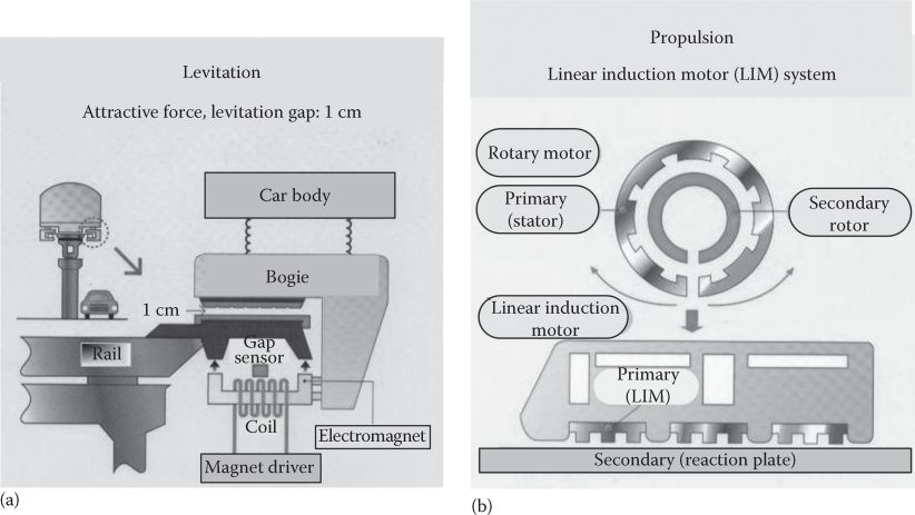
FIGURE 22.1 S. Korean LIM-MAGLEV: (a) cross section and (b) longitudinal view. (After Maglev (transport), Wikipedia, the free encyclopedia.)
The commercial LIM-MAGLEV of HSST commenced operation in March 2005 in Aichi, Japan, on a nine-station 8.9 km track known as LINIMO (Figure 22.2). The trains go up to 100 km/h and the track shows a maximum gradient of 6% and a minimum curve radius of 75 m.
Typical 8 mm airgap LIM propulsion performance when fed from PWM inverters for urban MAGLEVs is shown in Figure 22.3 (borrowed from Chapter 6).

FIGURE 22.2 “LINIMO” HSST (LIM-MAGLEV). (After http://en.wikipedia.org/wiki/File:Linimo_approaching_Banpaku_Kinen_Koen,_towards_Fujigaoka_Station.jpg)
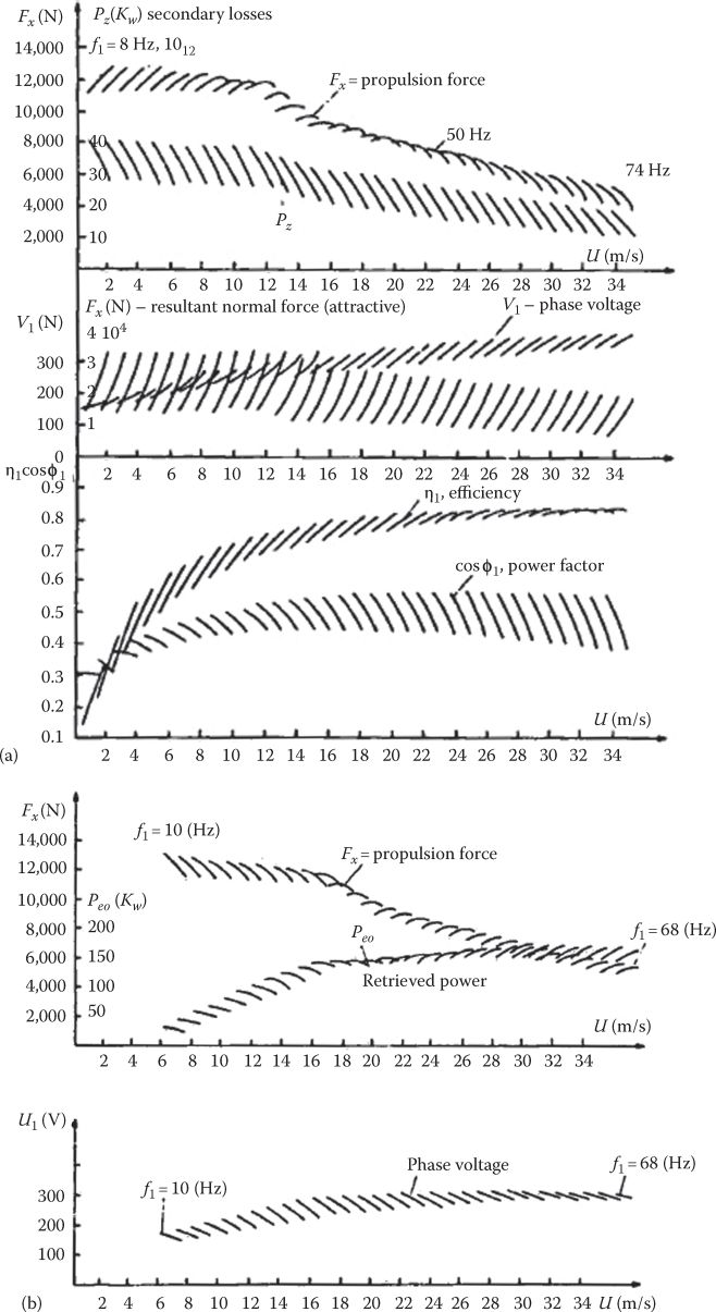
FIGURE 22.3 Typical performance with LIM in urban MAGLEVs: (a) propulsion and (b) regenerative braking.
The efficiency may also be around 0.8 (1.5 W copper stator losses/N of thrust), but the power factor is 0.4–0.5, which puts a notable burden on the on-board inverter kVA (weight and cost).
The (1.5–2) kW/ton of levitation/guidance is acceptably low. As the vehicle weight may be as low as mechanically feasible, reducing the weight of electric power equipment on board is a top priority to the point of minimum total net present value of the system (initial, plus energy, plus maintenance costs, for given commercial speed and traffic density).
22.2.1 Potential, Improved LIM-MAGLEV Concepts
Scarce data are available on the commercial (or close to) LIM-MAGLEV systems as they are in their early days. But it seems evident that some ways to reduce the passive track separate components (for levitation and propulsion), with the normal force of LIM put to work, and/or the integration of full levitation and propulsion in the LIM with cage secondary, are ways worth following. Figure 22.4 shows a potential configuration in which both the LIM and the dc controlled electromagnets (now with PM assistance), placed below the track, act along the same track.
Now the LIM normal force “helps” levitation if the former has an attraction character and its control, in general, can assist the levitation stabilization.
The LIM primaries are interspaced with levitation electromagnets along the vehicle sides, on board. The LIM interaction with the guideway (Figure 22.4) may produce some centralizing guidance force.
Levitation control, with PM-assisted electromagnets, may be approached as zero current control (between, say, 70% and 120% rated airgap) and, then, safety airgap control takes it over (see Chapter 19).
The FOC of LIM through id current (Chapter 6) can provide levitation assistance control by damping vertical oscillations.
Decoupled control of LIM levitation (through id) and propulsion (through iq) functions by FOC (or direct thrust and normal force control) is essential for good dynamic MAGLEV performance.

FIGURE 22.4 Integrated propulsion-levitation guideway with LIM + PM assisted dc control levitation electromagnets.
However, secondary-bogie and tertiary-cabin mechanical suspension systems are required to reduce “unsprung” mass and provide good ride comfort, even in urban LIM–MAGLEVs.
Another possibility is to use LIMs for full levitation and propulsion control, when higher airgap flux density is required (0.6 T or more). For a 6–10 mm mechanical airgap, this implies a cage secondary (placed in a coarse lamination iron core) along the track (Figure 22.5a).
The potential control system in Figure 22.5b shows that, with a sec ondary flux observer (which may integrate an airgap observer), the secondary flux position is estimated (Chapter 6 on LIMs). The robust SM + PI close loop regulators should handle both levitation and propulsion control with variable airgap: from start (2grated) to grated ±20% (for cruising). Needless to say that multiple LIM units (4 k units; k ≥ 1) per cabin are required, each with its own PWM inverter and decentralized control, if the secondary and tertiary mechanical suspensions alleviate enough the interaction between LIM units.

FIGURE 22.5 Generic integrated propulsion and full levitation LIM on urban MAGLEVs: (a) the system topology and (b) potential control system.
The cage secondary of LIM may not cost too much to be practical for urban MAGLEVs; it is a mandatory solution to produce full levitation/propulsion by LIM for levitation force per LIM primary weight greater than 10–1. If in a vehicle the LIMs weigh 10% of all weight, then a 1.0 m/s2 acceleration is available. This is enough in practice.
22.3 H-LSM MAGLEV (Magnibus)
The Magnibus [2] system (Figure 22.6) uses linear homopolar (inductor) synchronous motors for integrated propulsion and full levitation. Guidance is provided by separated dc controlled electromagnets on board, interacting with lateral track solid iron guideway slabs (Figure 22.7).
For details on H-LSM, see Chapter 8.

FIGURE 22.6 Photograph of Magnibus. (After Boldea, I. et al., IEEE Trans., VT-37(1), 213, 1988.)
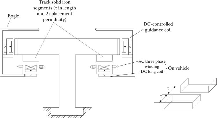
FIGURE 22.7 H-LSM MAGLEV system. (After Boldea, I. et al., IEEE Trans., VT-37(1), 213, 1988.)
The main data of the experimental Magnibus-01 [2] are given in Table 22.1.
The levitation model, considered only for the dc winding of H-LSM in Figure 22.8a, has a structural diagram as in Figure 22.8b. The airgap δ and the absolute acceleration are measured. Based on them an observer for airgap variation speed is built and integrated in a compensator that handles track irregularities accelerations indirectly (Figure 22.9).
The complete levitation control system (Figure 22.10) includes the compensator in Figure 22.9, but also adds the following:
An outer PI airgap close loop regulator.
An interior flux ΨT estimator signal (obtained with an emf search coil filter): this tends to “linearize” the system (Chapter 19) and thus yields good levitation control from 20 to 2 mm airgap. The flux derivative () and airgap sensor coils’ positioning is shown in Figure 22.11. The airgap sensors operate around resonance at 100 kHz and thus produce reliable outputs.
TABLE 22.1
Magnibus-01 Data
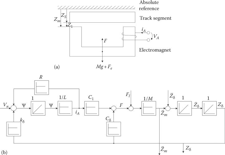
FIGURE 22.8 (a) Levitation model and (b) its structural diagram.

FIGURE 22.9 Compensator with observer.

FIGURE 22.10 Complete levitation control system.
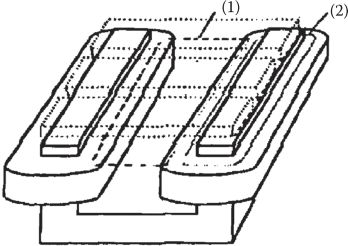
FIGURE 22.11 H-LSM with: (1) airgap sensor air-core coil and (2) flux derivative ΨT sensor coil.
The airgap and acceleration sensors’ basic circuits are given in Figure 22.12.
In the Magnibus-01, a single quadrant fast-thyristor dc–dc converter (Figure 22.13a) with bipositional (fast) control (Figure 22.13b) was used. Today IGBT 2-quadrant dc–dc converters are standardly used for fast response in levitation systems (Transrapid, etc.)
As all 4 H-LSMs, placed at vehicle corners, are fixed to the bogie with secondary mechanical suspension systems, decentralized levitation control was successfully applied.
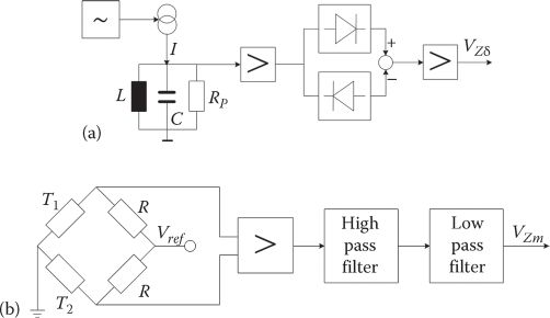
FIGURE 22.12 Airgap sensor (a) and acceleration sensor (b) basic circuits.
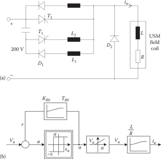
FIGURE 22.13 DC–DC one quadrant fast thyristor chopper (a) with bipositional control system (b).
Typical vehicle lifting (takeoff) standstill experimental transients from 20 to 12.5 mm and landing are shown in Figure 22.14 [2]; well-behaved responses are visible.
Responses to perturbations from neighboring H-LSMs are illustrated in Figure 22.15.
Finally, one airgap variation during vehicle acceleration and deceleration (with vehicle braking and speed reversal) is visible in Figure 22.16.
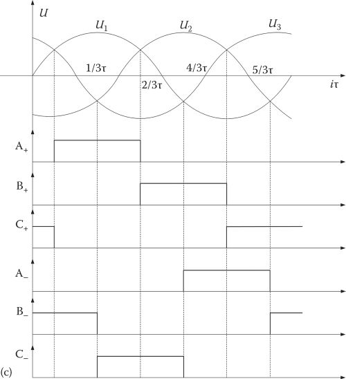
The position sensor with coils in air and its six signals per period are presented in Figure 22.17.
So rectangular current control in the current source inverter was used. Today, voltage-source PWM inverters could be used and motion-sensorless control for propulsion can be adapted.
It is feasible to use an inverter for each H-LSM primary and thus produce propulsion control so as to damp vehicle parasitic motions along the vertical axis.
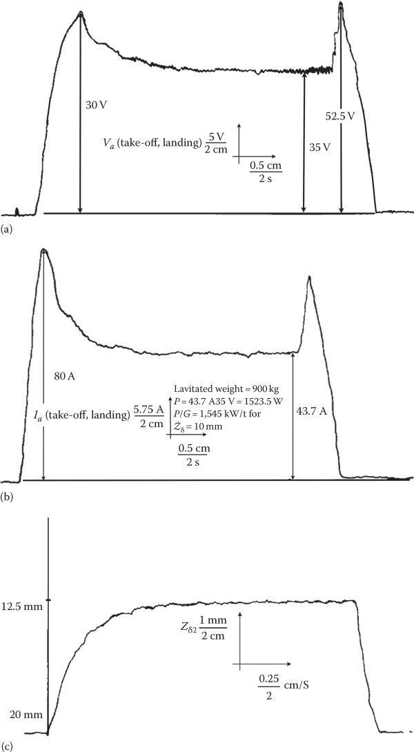
FIGURE 22.14 Experimental levitation takeoff (lifting) and landing at zero speed: (a) voltage, (b) dc current, and (c) airgap.

FIGURE 22.15 Responses to perturbations from neighboring H-LSMs.
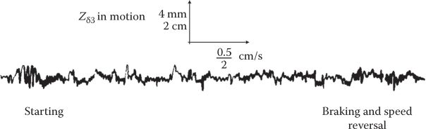
FIGURE 22.16 One airgap during Magnibus-01 acceleration, regenerative braking, and speed reversal.
Experimental results have proved the following:
At least (7–10)/1 levitation force to weight of H-LSMs, which would allow a 1 m/s2 acceleration of the vehicle, with natural cooling.
H-LSM total efficiency at 5–10 m/s was above 0.80 (this includes levitation power losses).
Power factor of H-LSM at 5–10 m/s was about 0.8 lagging, thus leading to reasonable inverter kVA ratings (and costs and weight).
In general, the thrust (propulsion force) was produced with 1.5 W loss/N of thrust.
DC windings power used for both, levitation and propulsion, amounts to 1.6–2 kW/ton.

FIGURE 22.17 Position sensor for H-LSM control: (a) main circuits and (b) layout. Position sensor for H-LSM control: (c) output signals.
It is argued here that this superior performance might render Magnibus as feasible not only for urban but also for interurban use (up to 400 km/h or more). The vehicle independence in its full control, the passive track simplicity, and lower cost (even at mild traffic density), including simpler guideway switches, are the main merits of Magnibus, in addition to lower losses and better power factor. But, as in any passive guideway MAGLEV, full power transfer to the vehicle is required.
For more on H-LSM and attraction-force levitation details, see Chapters 9 and 19.
22.4 Potential Improvements on Magnibus System
Integrating not only propulsion and levitation by H-LSM but also controlled guidance (even for high speeds), while not increasing the segmented track weight, is illustrated in Figure 22.18.
The topology evidences:
The permanent magnets (PMs) in a strong flux concentration configuration produce a rather large (larger than 1.2 T (1.4 T if possible)) flux density in the airgap between the track segments and the primary “teeth.” The PMs alone should be able to suspend the vehicle at rated airgap for rated weight. When the weight increases, suspension is provided at a smaller gap; at lower weight the airgap is larger. In this case, the two coil currents ic1,ic2 contain the components ilev, which are controlled to zero (as in Chapter 19), unless the airgap goes out of the safe interval, (0.6–1.2)grated, when airgap control (with nonzero dynamic is performed.
On the other hand, the inclined airgaps (Figure 22.18a) produce additional levitation force and opposite guidance forces. The guidance force control is managed by the currents iguide (same in both coils). The inclination angle may be designed to best suit the guidance and levitation force requirements.

FIGURE 22.18 PM-assisted H-LSM MAGLEV (Magnibus 02): (a) cross section, (b) track segments, and (c) ac winding.
Two dc–dc converters are required, and the frequency band of the levitation and guidance functions should be decoupled.
If the PMs alone cannot lift the vehicle, then the ilev will not be regulated around zero but around a nonzero value required for steady-state full levitation.
In any case, the efficiency of the integrated propulsion-levitation guidance is improved above 90% due to PMs doing the main job, while the track weight remains remarkably small.
It is almost needless to say that the same concept may be used by excluding the ac three-phase winding and making both the guideway and the primary core continuous, along the direction of travel, into a hybrid (PM assisted) levitation-guidance system suitable for LIM-MAGLEVs, etc.
22.5 Transverse-Flux PM-LSM MAGLEVs
The transverse-flux PM-LSM (Chapter 14) has already been proposed (theoretically) for MAGLEVs in 1995, by its inventor [3] (Figure 22.19), despite the fact that the normal force/thrust ratio is only 3(4)/1, in general.
The TF-LSM has only PM excitation and long (multiple pole span) ac coils [4]. To reduce the track weight, TF-LSM uses single-phase blocks placed one after the other (shifted properly in the direction of motion) to produce, say, a three-phase machine (Figure 22.19b). It should be mentioned that the variable reluctance track (at 6–10 mm airgap) does show at best a 2/1 saliency ratio, and it has to be made of silicon laminations to avoid very large eddy current losses (a large drag force, also).
As the PM-produced maximum flux density in the airgap is basically ac and may hardly go over 1–1.2 T, due to very large flux fringing (leakage), and the iron to iron primary/secondary areas are at most 1/3 of total airgap primary area, there is not enough levitation force for full levitation of the vehicle as already mentioned (a 10/(15)/1 normal/thrust force is required for full levitation).
However, as in any linear synchronous machine, whose vector diagram is shown (in primary coordinates) in Figure 22.20, there is one more “tool” to produce additional levitation force: positive (magnetizing) id current:

FIGURE 22.19 Proposed TF-LSM MAGLEV: (a) MAGLEV structure and (b) primary/secondary. (After Weh, M., Linear electromagnetic drives in traffic systems and industry, Record of LDIA-1995, Nagasaki, Japan, pp. 1–8, 1995.)
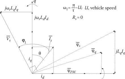
FIGURE 22.20 H-LSM vector diagram (steady state) in dq (primary coordinates).
It is a known fact that the normal (attraction) force is proportional to the airgap flux linkage Ψg amplitude squared:
Neglecting the leakage inductance, it may be said that ; but, with the large airgap of MAGLEVs, the error would be more than 50%.
The airgap flux Ψg is related to total airgap flux density in the airgap (Bg), which explains (22.2):
Both id and currents produce an increase in levitation force but id more so, despite the fact that Lq > Ld (by 20%–30% only, however)
As the magnetic salience is very moderate Lq/Ld < 1.3, id does not produce a large braking force due to the reluctance effect:
However, the negative reluctance thrust (for id > 0) has to be considered in the propulsion design.
Moreover, a positive leads to a lower power factor (φ1 lagging), and thus the inverter kVA ratings are slightly increased.
But the fact that levitation and propulsion are handled only by the vector control (FOC) or direct thrust and normal force (airgap) control of PWM inverter is an important merit that may deserve full technical and economic investigation in full-scale applications (Figure 22.21).

FIGURE 22.21 Generic levitation and propulsion control in a TF-PM-LSM potential MAGLEV.
The thrust multiplier character of the ac multi-pole coil windings on TF-PM-LSM leads to lower copper losses/thrust, if the number of poles is large enough to cancel the fringing flux adverse effects, but at the cost of higher core losses due to higher fundamental frequency. An optimum problem is sensed here.
The twisting (by pole pitch τ) of the guideway laminated cores (Figure 22.19b) remains a serious practical problem, but not so for industrial platforms (short travel).
22.6 Dc-Polarized L-SRM MAGLEVs
A PM-less solution that maintains the transverse-flux topology but simplifies the guideway laminated segments stems from the dc-polarized linear switched reluctance motor (Figure 22.22).
The number of primary and secondary poles (τ) is the same (as in TF-PM-LSM) and may be large; in principle τ > (5–7)g; (g-the airgap).
The dc coils are connected in series to cancel the total emf induced in them due to “full” coupling of each of them with one ac coil.
Provided the homopolar flux dc coil airgap flux density Bdc ≈ 1.5T in the airgap has a rather sinusoidal strong ac component B~, the ac currents in the phases may be sinusoidal and thus vector control may be used in a standard PWM inverter. An additional leg for the controlling of idc. for levitation control is added (Figure 22.22c).
Basically, the normal force and thrust density are similar to those of H-LSM but with the additional advantage of moderate copper losses due to multiple (long) dc and ac coils (one ac coil per phase module), typical to transverse-flux machines. But, for g = 6–10 mm a saliency ratio of maximum 2/1 may be hoped for in a rather small pole pitch design (τ > (5–7)g), required for high force densities.
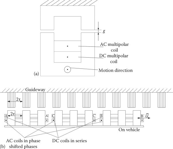
FIGURE 22.22 DC-polarized L-SRM potential MAGLEV: (a) cross section, (b) longitudinal view. DC-polarized L-SRM potential MAGLEV: (c) inverter structure.
The equivalent power factor of dc polarized L-SRM is basically lower than that of H-LSM, leading to a larger kVA inverter on board the vehicle.
Moreover, the guideway segments have to be made of laminated steel as they experience notable ac magnetic fields. This leads to added guideway costs in comparison with the solid iron segments for H-LSM.
It may be argued that dc + ac currents could be handled in the same coils of system in Figure 22.22. True, but then the whole inverter control has to be changed. This proposal is here to inspire new research, as comprehensive efforts—in theory and testing—are required to prove this solution, or other similar ones, practical or impractical for MAGLEV vehicles; for industrial platforms, however, its simplicity makes it very tempting.
22.7 Multiphase (True Brushless) Linear Reluctance Machine MAGLEVs
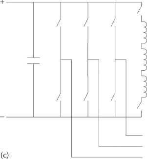
Known also as “flux regulated reluctance machine” [5], the two-level bipolar current brushless reluctance machine [6] may be adapted, in its linear counterpart, for MAGLEVs to produce integrated propulsion and levitation with a good power factor (Figure 22.23a and b).
The machine resembles the behavior of a nonexcited dc brush machine with brushes moved from the neutral axis to the high saliency pole corners (Figure 22.24).
Out of the six phases (Figures 22.23 and 22.24), ideally two (A and B in this moment) are field phases and the other four (C, D, E, F) are thrust (torque) phases, as in the dc brush machine with shifted brushes and no excitation.
Each phase “switches” roles based on mover (vehicle) position (Figure 22.23b). As expected, for given thrust, the minimum copper losses occur when (field and thrust current levels are equal to each other).
The summation of currents may not always be zero, and thus an additional leg in the inverter handles the null current (Figure 22.23b).
The higher the saliency the better, but for large airgap long travels (MAGLEV vehicles), even a segmented (one piece per pole) laminated guideway may do.
As most of the primary area is active, a higher thrust and normal force density than most previous passive (or active) guideway MAGLEVs may be expected. So a 2.5/1 saliency ratio may already be acceptable.
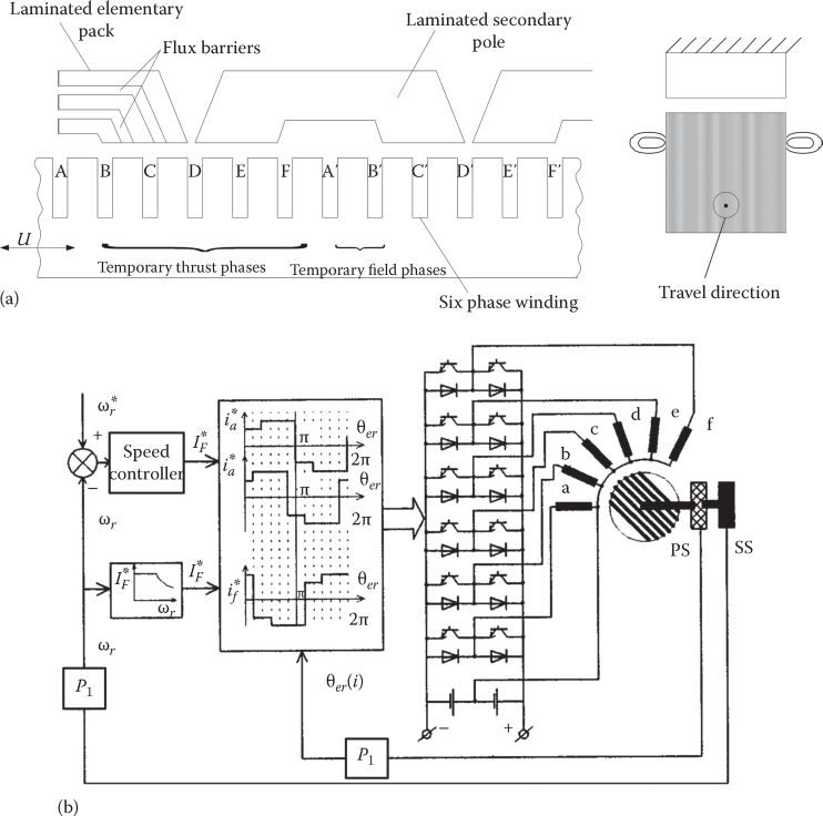
FIGURE 22.23 Generic bipolar two-level current L-RSM MAGLEV: (a) longitudinal cross section and (b) inverter dedicated topology. (After Boldea, I., Reluctance Synchronous Machines and Drives, Oxford University Press, 1996.)
The flat top level of currents leads to a better inverter voltage (and kVA) utilization, with an ideal value closer to unity equivalent power factor.
The levitation force is mainly controlled through the field phases and thrust by the thrust phase currents . Six proximity (Hall type) position sensors (placed in slot tops) are required to “command” the bipolar two-level current waveforms (Figure 22.22b). Motion sensor-less propulsion control may also be feasible.
There is some interference between levitation and propulsion, but it is rather small as the two currents’ fields are basically orthogonal and always “tied” to the track poles position. (It may be inferred that even solid segments for a coarse lamination guideway may be used due to this characteristic).
More than six phases may be used but, to limit the pole pitch in MAGLEV vehicles, six phases are considered a safe design start-up. A larger pole pitch leads to thicker guideway poles and thicker back iron in the primary.
It has to be recognized that the pole-span ac coils in the discussed solution mean larger copper losses than for the long (multiple-pole span) coils of TF-RM-LSM. But the normal forces and thrust densities are at least larger, for a better kVA rating utilization (power factor) in the inverter and lower iron losses (lower frequency due to larger pole pitch); moreover, no PMs are required in the solution in Figure 22.23, though low-cost (Ferrite) PMs may be added for better performance.

FIGURE 22.24 DC-brush unexcited machine analogy.
Tooth-wound dc + ac coil primaries, with variable reluctance secondary rating motors, may be “converted” to linear counterparts and tried for MAGLEVs [7,8]. However, it seems rather evident that the thrust density and power factor are notably lower than for the previously mentioned proposals.
All in all, these three competitive MAGLEV solutions look worthy of thorough quantitative analyses—technically and economically—for MAGLEV vehicles or for industrial platforms.
22.8 Summary
Passive guideway MAGLEVs refer to magnetically levitated “people movers” or industrial platforms with linear electric motor propulsion and passive (no PMs and no supplied windings) secondary (guideway).
With all power equipment (for propulsion, levitation, guidance, and auxiliaries) on board of vehicle, full electric power transfer to the vehicle is required.
Though the PWM inverters and full power collectors for propulsion are placed on board, the recent progress in power electronics with IGBT and IGCT PWM inverters has led to notably less than 1 kg/1 kVA with forced cooling; thus, the burden of power electronic weight on board is rather mild, allowing for enough load weight.
Also, controlled mechanical-friction multi-MW power transmission to vehicles up to more than 500 km/h peak speed has been demonstrated with wheeled trains (TAGV, France); the inevitable wearing of the power collector due to accidental arching has been reduced to practically acceptable costs.
This is how the passive guideway MAGLEV merits come into play:
Simpler (passive) guideway for electromagnetic propulsion, levitation, and guidance, at lower initial cost.
Standard power substations; even if single-phase ac 15 KV power is brought on board of such MAGLEV vehicles, the incurring step-down transformer and diode rectifier seem an acceptable burden.
Standard 800–1500 V dc power substations may be used for urban and suburban MAGLEVs.
The land intrusion and on ground stations’ man supervision resources are much smaller than for active guideway MAGLEVs.
Each vehicle (train) is fully independent and thus, when faulty, it is simply taken off the track.
The guideway switches at intersections are much simpler than for active guideway MAGLEVs.
Linear induction motor LIM propulsion with separate dc controlled electromagnets (without or with PM assistance) for levitation and guidance solutions [9] has led to the first commercial (and close to two) LIM-MAGLEVs for urban transportation.
The ruggedness of LIM and its rather straightforward sensorless indirect field-oriented control from zero speed makes the solution attractive.
However, the small but downward normal (attractive) force in LIM is opposite to the levitation force of dc controlled electromagnets, to preserve acceptable LIM efficiency (about 80%!) at still rather low, lagging, power factor (0.45–0.6) for 6–10 mm mechanical airgap.
Moreover, the separate power electronics for full control of levitation and guidance may add notably (in peak kVA) to the vehicle full power rating and even weight (and cost).
But, still, levitation and guidance may be provided at 2 kW/kg of vehicle for urban applications (20 m/s or so); to reduce this further, PMs are placed in electromagnets to cover full vehicle weight; and zero current control (at slightly variable airgap) for levitation (not done yet) may lead to 1 kW/kg for levitation and guidance (airgap control, instead of zero current control, is needed when the airgap exits the safe zone: of 0.6–1.2 rated value).
A guideway structure, which serves both (by the solid iron core) the LIM and the levitation-guidance electromagnets, may use the LIM normal force for levitation control (or at least for vertical oscillations damping), when PMs are inserted in the levitation-guidance electromagnets.
The full levitation control by LIMs—with no additional electromagnets—may be approached with cage (ladder) secondary in a coarsely laminated slotted iron guideway; at least for urban MAGLEVs and industrial platforms, this solution seems a way of the future.
In order to reduce further the vehicle weight/passenger, mainly the electromagnetic and power electronics equipment peak KVA and weight, and further simplify the passive guideway, the homopolar linear synchronous motor (H-LSM) MAGLEV (Magnibus) concept was introduced and tested on a 150 m track with a 4 ton prototype.
This time the propulsion and levitation passive track was made solely of solid mild iron segments with one pole pitch (out of two poles length) span. Separate lateral solid iron slabs in the guideway interact with additional guidance controlled electromagnets. As with forced cooling the H-LSM levitation force/weight may over pass 10/1 and levitation to propulsion force ratio is around 10(12)/1, the Magnibus system can provide 1–1.2 m/s2 acceleration if the weight of H-LSMs represents 1/10(12) of vehicle total weight, which is quite reasonable.
Also, because the eddy current drag force in the track solid iron segments due to the dynamic longitudinal effect is less than 10%–15% of rated thrust even at 300 km/h, the Magnibus system concept may be extended at 400 km/h interurban MAGLEVs.
In urban MAGLEVs, the Magnibus system provided a total levitation-propulsion efficiency between 5 and 10 m/s of more than 80% at lagging power factor (iq pure control) of 0.8 or slightly more, for an airgap of 10 mm. In addition, the ac copper losses per thrust was about 1.5 W/N.
To further improve the total efficiency above 90%, a PM-assisted H-LSM capable of controlled propulsion, levitation, and guidance was introduced in this chapter. The levitation and guidance control are now handled mainly by two dc long coil currents with opposite (±ilev) current components for levitation and guidance control (±iguide). Two dc–dc 2 quadrant converters control levitation and guidance. The segmented guideway weight (cost) is also notably reduced.
One more transverse-flux PM-LSM passive guideway MAGLEV concept is illustrated, where both propulsion and levitation are controlled through a simple inverter at good efficiency (90%) but at lower power factor (0.6–0.7). Moreover, as the levitation/thrust ratio is only 4/1, to secure 1–1.2 m/s2 vehicle acceleration, notably more flux density in the air-gap should be provided by the ac winding d and q currents (in the orthogonal model). This will lower overall efficiency notably; also, the decoupled levitation-propulsion control seems a daunting job. A laminated segmented track is required, though. However, the solution seems to deserve full-scale vehicle experiments, especially for industrial MAGLEV platforms.
Finally, two more PM-less passive guideway MAGLEV solutions have been proposed:
The dc polarized transverse-flux linear dually salient machine MAGLEV
The bipolar two-level multiphase (six phases) linear reluctance machine MAGLEV
They should provide full levitation and propulsion control (also some guidance (centralizing) force), with the first one providing better efficiency at lower power factor than the second one; both solutions require laminated variable reluctance secondary (track).
In conclusion, passive guideway MAGLEVs have revived and will do even better in the future for urban and then for interurban MAGLEV vehicles [10–12] and industrial platforms as power electronics weight is small enough to be accepted on board and full power transfer to vehicle up to 500 km/h in the MW range has become practical.
The passive guideway and of on ground standard power substations and its switches, the independent control of vehicle from on board at notably smaller Wh/passenger/km than for wheeled vehicles at comparative speed, and lower guideway maintenance (due to 104 smaller stress because of force distribution over a large area) make MAGLEVs, in our view, a viable part of the future of transportation. The technology is here to stay and progress.
References
2. I. Boldea, A. Trica, G. Papusoiu, and S.A. Nasar, Field texts on a MAGLEV with passive guideway linear inductor motor transportation system, IEEE Trans., VT-37(1), 1988, 213–219.
3. M. Weh, Linear electromagnetic drives in traffic systems and industry, Record of LDIA-1995, Nagasaki, Japan, 1995, pp. 1–8.
4. T.-K. Hoang, D.-H. Kang, and J.-Y. Lae, Comparisons between various designs of transverse flux linear motor in terms of thrust and normal force, IEEE Trans., VT-46(10), 2010, 3795–3801.
5. J.D. Law, A. Chertox, and T.A. Lipo, Design performance of the field regulated reluctance machine, Record of IEEE-IAS-1992 Meeting, Houston, TX, Vol. 1, 1992, pp. 234–241.
6. I. Boldea, Reluctance Synchronous Machines and Drives, Chapter 6, Oxford University Press, 1996.
7. A. Zulu, B. Mecrow, and M. Armstrong, A wound-field three-phase flux-switching synchronous motor with all excitation sources on the stator, IEEE-ECCE-2009, 2009, pp. 1502–1509.
8. E. Sulaiman, T. Kosaka, and N. Matsui, A new structure of 24 slot/10 pole field excitation flux-switching synchronous machine for hybrid electric vehicles, Record of EPE-2011, Birmingham, U.K., 2011, pp. 1–10.
9. S. Kusagawa, K. Shutoh, and E. Masada, Electro-magnet suspension system with fuzzy control for a magnetically levitated railway system, Record of LDIA-2003, Birmingham, U.K., 2003, pp. 263–266.
10. B.S. Lee, Linear switched reluctance machine drive with electromagnetic levitation and guidance system, PhD Thesis, Virginia Tech, Blacksburg, VA, 2000.
11. I. Boldea and S.A. Nasar, Linear Electric Actuators and Generators, Cambridge University Press, London, U.K., 1997.
12. D.H. Kang, Design of PM excited transverse flux linear motor of inner mover type, KIEE, 5-B(2), 137–141, 2005.