Microsoft Windows Server 2003 supports two high availability clustering technologies: Network Load Balancing (NLB) clusters and server clusters. Microsoft does not support combining NLB clustering with server clustering. This chapter describes the two types of clustering supported by Windows Server 2003, their place in the enterprise, and their configuration and requirements. Finally, we’ll take a brief look at a new Microsoft clustering technology that is designed to support high-performance computing (HPC)—Microsoft Compute Cluster Server 2003.
A cluster is a group of two or more computers functioning together to provide a common set of applications or services with a single apparent identity to clients. The computers are physically connected by hardware in the form of either a network or shared storage. The clustering software provides a common interface externally while managing the resources and load internally.
Windows Clustering provides the following benefits:
High availability. When a clustered application or service fails or a computer in the cluster fails, the cluster responds by restarting the application or service on another member of the cluster or by distributing the load from the failed server to the rest of the cluster.
Scalability. For cluster-aware applications, adding more machines to the cluster adds capabilities.
Manageability. Administrators can move applications, services, and data from computer to computer within the cluster, allowing them to manually balance loads and to offload machines scheduled for maintenance.
NLB—known as the Windows Load Balancing Service in Microsoft Windows NT 4—gives TCP/IP-based services and applications high availability and scalability by combining up to 32 servers running Windows Server 2003 in a single cluster. By combining NLB with round-robin DNS, NLB clustering can scale well beyond 32 servers. Client requests for applications and services provided by the cluster are distributed across the available servers in the cluster in a way that is transparent to the client. NLB clusters are supported in all versions of Windows Server 2003.
If a server fails or is taken offline, the cluster is automatically reconfigured and the client connections are redistributed across the remaining servers. If additional servers are added to the cluster, they are automatically recognized and the load is reconfigured and distributed.
Server clusters distribute the workload among the servers in a cluster, with each server running its own workload. Like other types of clusters, server clusters are scalable and highly available. In the event of a failure, applications and services that can be restarted, such as print queues and file services, are restarted transparently. Ownership of shared resources passes to the remaining servers. When the failed server becomes available again, the workload is automatically rebalanced.
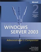
Windows Server 2003 supports server clusters only in the Enterprise and Datacenter Editions. There are three basic types of server clusters supported by Windows Server 2003: single node clusters, single quorum device clusters, and majority node set clusters, as shown in Figure 19-1.
In deciding whether and how to implement clustering, you first need to understand what problem is being solved and how best to solve it using the available technologies. Then you can make a business case for the particular solution or combination of solutions that best solves the particular problem. This section describes various scenarios and the type of clustering appropriate for each.
An intranet or Internet server is a prime candidate for an NLB cluster. By enabling an NLB cluster across multiple servers, you provide your site with both redundancy and increased capacity. If a server should fail, the load is distributed transparently among the remaining servers.
Each Web server in the cluster runs its own Web server and accesses only local Web pages. This version is "shared nothing" clustering—there are no shared disks and no shared applications or data, with the possible exception of a common back-end database. NLB clusters are an appropriate and relatively inexpensive way to achieve both redundancy and high availability for your Web site, whether it’s internal or external. Clients that need access to the Web pages are distributed among the servers in the cluster according to the load at each server. What makes this work is that most Web pages change infrequently, allowing manual updates of all Web servers with the same information when you need to make changes.
Starting with Windows Server 2003, Terminal Services now supports clustering using NLB clusters and the new Session Directory to distribute Terminal Services sessions across a farm of servers running Terminal Services, allowing for high availability and load balancing and presenting a single face to Remote Desktop clients. If you have large numbers of Terminal Services users, moving to Windows Server 2003 and enabling NLB clustering for your servers running Terminal Services gives you additional flexibility, redundancy, and improved user experience for your Terminal Services users. For more information about Terminal Services Session Directory, see http://www.microsoft.com/windowsserver2003/techinfo/overview/sessiondirectory.mspx.
If your business absolutely, positively can’t be run without a certain application or set of applications, you need a highly reliable server to make sure that the application is always available. A server cluster is a good solution in this scenario, providing both high availability and scalability. With a server cluster, you organize your critical applications into groups, one group to a server. All the resources for each group are self-contained on the server, but if any server in the cluster fails, the others pick up the services and applications from the failed server, allowing for continuous availability of critical services and applications. You can control the failover and fallback actions for each server and clustered resource.
Server clusters require a substantially greater investment in hardware than NLB clusters. In addition, with the exception of majority node set clustering, they aren’t suitable for "shared nothing" clustering, because they use a shared disk array to keep resources in sync. When a server fails, the other server picks up the applications that had been running on the failed server. Because the disks are shared, the remaining server has access to the same set of data as the failed server, and thus there is no loss of functionality. The exception to this is majority node set (MNS) clustering, which does not use a shared disk quorum resource but rather replicates data across the cluster to local quorum disks. Majority node set clustering is appropriate for geographically diverse clusters and requires specialized support from original equipment manufacturers (OEMs) and independent software vendors (ISVs). For a TechNet support webcast on MNS clustering, see http://support.microsoft.com/kb/838612.
Before you attempt to implement any form of clustering, you need to clearly understand the business reason for doing so. You also need to be aware of the costs and benefits of the implementation, as well as the resource requirements for a successful implementation. Treat the implementation of a Windows Server 2003 cluster as you would any other major project. Clearly state the business case for the cluster, and obtain a commitment from all levels before you expend substantial resources on the project.
The first step in planning your cluster is to identify your goals for the implementation and the needs that using clusters will meet. This sounds obvious, but it is actually the part of the process that is most often overlooked. The implementation of any technology should always be first and foremost a business decision, not a technology decision. Creating and maintaining clusters is not a trivial task, and it requires both technological and financial resources. You’ll have a hard time selling your project if you haven’t clearly identified one or more needs that it will meet.
In identifying the needs to be met and the goals of your project, you need to be as objective as possible. Always keep in mind that what you might view as "cool" technology can look remarkably like scary, unproven gobbledygook to those in the organization who are less technically savvy than you are. This doesn’t mean that those individuals won’t support your project, but it does mean that you need to make the case for the project on a level that they can understand and identify with.
Start by clearly identifying the business goals that you’re trying to accomplish. State the general goals, but provide enough detail to make the success of the project clearly measurable. Identify the specific gains you expect and how those gains will be measured. Be sure to clearly indicate how the needs you’ve identified are currently being met. This step is critical because it lets you point out both the costs of your suggested method and the risks associated with it.
Once you know the business needs you’re trying to meet, you can identify some solutions. If you’ve clearly laid out your goals and objectives for the project, the technology that achieves those goals will be driven by those needs, not the other way around. This is also the time to use your best political judgment. You need to identify not only the best way to meet the business needs, but also how much you can realistically sell and implement in a single shot. If you think that ultimately you will need a fully integrated, three-tiered, multiple-cluster solution, you might want to build your plan around a phased approach that allows you to distribute the risks and costs over a broader period.
In addition, if you’re proposing a clustering solution to the problem, spend some time and energy identifying methodologies that might be considered alternatives to clustering and clearly laying out the strengths and weaknesses of those alternatives. This effort will short-circuit objections and diversions as you build support for your project.
As you plan your schedule, be sure to identify the risks at each step of the process and plan solid fallback positions if problems arise. Selling the project is also much easier if it’s clear that you’ve actually thought about the risks. For example, if your goal is to replace an existing manual methodology, have you left yourself a way to fall back to it if there are problems? Or are the two mutually incompatible? If you’re replacing an existing client/server application with a clustered, Web-based, distributed, n-tiered application, have you drawn a clear roadmap for how you will make the transition from one to the other? What are the risks of that transition?
Spend some time identifying failure points in your project. If you’re building a server cluster to provide 24-hour, 7-day access to your Microsoft Exchange messaging, have you identified redundant network connections to the cluster? It does little good to create a highly available server if the network connection to it is questionable.
Take the time to identify all the possible pieces of your cluster implementation ahead of time. Use this to build a checklist of steps that you need to take and the dependencies at each point. At each major step, identify the hardware, software, knowledge, and resources required, and create a checklist of the prerequisites for that step. Use the checklists in the Windows Help for Cluster Administrator as a starting point, but build onto them with the details for your implementation and your environment. The time you spend planning your clustering implementation will easily be saved in the actual installation and implementation, and it greatly reduces your risks of failure.
NLB provides a highly available and scalable solution for TCP/IP-based network applications such as a Web server or FTP server. By combining the resources of two or more servers into a single cluster, NLB can provide for redundancy of information and resources while servicing far more clients than a single server alone could handle.
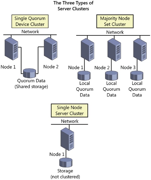
NLB is a Windows Server 2003 networking driver. It acts independently of the TCP/IP networking stack and is transparent to that stack. The NLB driver (Wlbs.sys) sits between the TCP/IP stack and the network card drivers, with the Windows Load Balancing Service (Wlbs.exe)—the necessary NLB control program—running on top, alongside the actual server application. (See Figure 19-2.)
Note
The Windows Load Balancing Service (Wlbs.exe) has been renamed in Windows Server 2003 to the Network Load Balancing Service (Nlb.exe). However, Wlbs.exe can continue to be used interchangeably with Nlbs.exe to provide full compatibility with existing scripts and applications. New scripts and applications should reference Nlb.exe to avoid future deprecation of Wlbs.exe.
Optimally, each server participating in an NLB cluster should have two network interface cards (NICs), although this is not an absolute requirement. Communications and management are materially improved with two NICs, however, especially in unicast mode. (Unicast mode, as opposed to multicast mode, allows each NIC to present only a single address to the network.) Overall network throughput is also improved, as the second network adapter is used to handle host-to-host traffic within the cluster. NLB clustering is not a place to try to cut costs on network cards. Server-grade NICs will provide full network throughput while minimizing the load on the servers.
NLB supports up to 32 computers per cluster. Each server application can be balanced across the entire cluster or can be primarily hosted by a single computer in the cluster, with another computer in the cluster providing directed failover redundancy. For fully distributed applications, the failure of any single host causes the load currently being serviced by that host to be transferred to the remaining hosts. When the failed server comes back online, the load among the other hosts is redistributed to include the restored server. While NLB clustering does not provide the failover protection appropriate for databases, it does provide for high availability and scalability of TCP/IP-based applications.
Note
NLB is supported across the Windows Server 2003 family and requires that TCP/IP be installed. It works over Fiber Distributed Data Interface–based or Ethernet-based networks (including Wireless) from 10 megabits per second (Mbps) to 1 gigabit per second (Gbps). It uses from 250 KB to 4 MB of RAM and roughly 1 MB of disk space.
A host in an NLB cluster can use one of four models, each with its own merits and drawbacks. These models are as follows:
Single network adapter in unicast mode
Single network adapter in multicast mode
Multiple network adapters in unicast mode
Multiple network adapters in multicast mode
The choice of model for a given host and cluster varies depending on the circumstances, requirements, and limitations imposed on the design of the cluster. The sections that follow provide details on each of the models.
Note
NLB in Windows Server 2003 does not support a mixed unicast mode and multicast mode environment. All hosts in the cluster must be either multicast or unicast. Some hosts, however, can have a single adapter, whereas others have multiple adapters. In addition, NetBIOS cannot be supported in a single-adapter-only configuration.
A single network adapter running in unicast mode is in some ways the easiest type of host to set up, and with only a single adapter, it is cheaper than one with multiple network adapters. It does, however, impose significant limitations:
Overall network performance is reduced.
Ordinary communications among cluster hosts are disabled.
NetBIOS support is not available within the cluster.
Using multicast mode in clusters in which one or more hosts have a single network adapter means that normal communications are possible between hosts within the cluster. This capability overcomes one of the most awkward limitations of the single adapter in unicast mode. However, there are still the following significant disadvantages:
Overall network performance is reduced.
Some routers do not support multicast media access control (MAC) addresses.
NetBIOS support is not available within the cluster.
Using multiple network adapters in unicast mode is generally the preferred configuration. It does impose the cost of a second network adapter per host, but given the relatively low cost of network adapters, including the per-port cost of hubs, this is a relatively minor price to pay for the resulting advantages:
No limitations are imposed on ordinary network communications among cluster hosts.
Ordinary NetBIOS support is available through the first configured adapter.
No bottlenecks occur as a result of a single network adapter.
The model works with all routers.
If you are forced by circumstances to use some hosts within a cluster that have only a single network adapter and you must be able to maintain normal network communications among the hosts in the cluster, you must run all the hosts in multicast mode, even those with multiple adapters, because you can’t run some hosts in unicast mode and some in multicast mode. This limitation could cause a problem with some routers, but otherwise it is a viable solution.
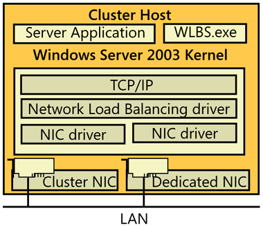
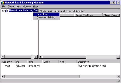
Creating an NLB cluster requires using the Network Load Balancing Manager, shown in Figure 19-3. This new manager simplifies the creation and management of NLB clusters, bringing all the pieces into a single management interface. You can connect to the NLB with the NLB Manager on any address in the cluster, including private addresses or the shared public address.
To create a new NLB cluster, follow these steps:
Open the Network Load Balancing Manager from the Administrative Tools folder, as shown in Figure 19-3.
Right-click Network Load Balancing Clusters in the left pane and select New Cluster, as shown in Figure 19-4.
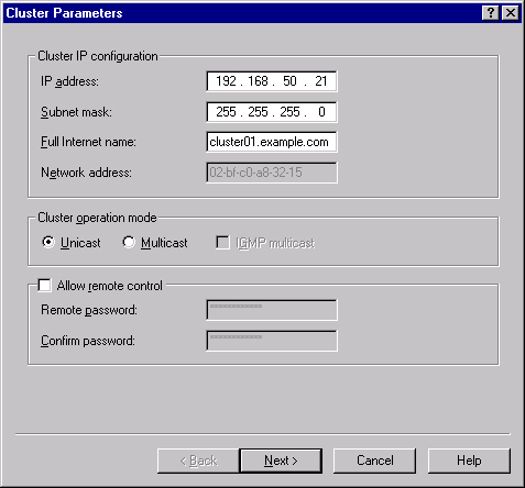
In the Cluster Parameters screen, shown in Figure 19-5, you need to enter an IP address, subnet mask, and the fully qualified domain name (FQDN) that the cluster will be known by. This IP address is a fixed IP address, so it can’t be a DHCP address.
Select whether the cluster will be unicast or multicast and whether you will allow remote control. Then click Next.
Important
Allowing remote control of a cluster is a significant security issue. Before you decide to enable this, carefully consider the consequences and understand the risks. If you do decide to enable remote control of your cluster, you should enforce sound password rules on the remote password. For more information about NLB security, see http://www.microsoft.com/technet/prodtechnol/windowsserver2003/technologies/clustering/nlbsecbp.mspx.
If the cluster will have additional IP addresses, enter them in the Cluster IP Address screen, and then click Next.
You can enter port rules in the next screen, or wait to configure these after you get the cluster up and running. Port rules can be used to control the behavior of various types of TCP/IP traffic. Windows Server 2003 allows you to configure different port rules for different IP addresses. Click Next when you have configured any rules you want to configure at this point.
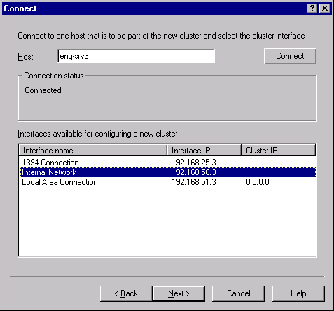
Enter the name or IP address of the first host that will be joined to the cluster in the Connect screen, shown in Figure 19-6. Click Connect to connect to the server and bring up a list of network interfaces available. Highlight the interface that will host the public traffic of the cluster (as opposed to private, node-to-node traffic).
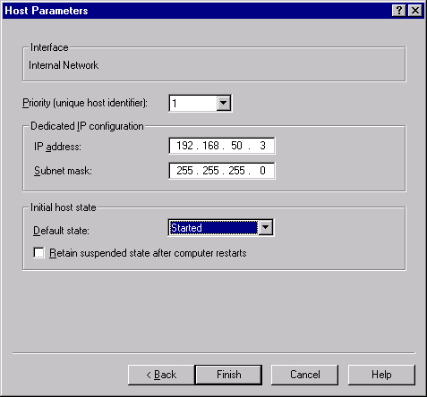
Click Next to bring up the Host Parameters screen, shown in Figure 19-7. Here you set the priority for this host of the cluster and the dedicated IP address that will be used to connect to this specific server (as opposed to the cluster as a whole). This IP address must be a fixed IP address, not a DHCP address. Finally, set the initial state of this host when Windows is started.
Click Finish to start up the NLB service and configure the server into the new cluster.
To add another node to an existing NLB cluster, follow these steps:
Open the Network Load Balancing Manager from the Administrative Tools folder.
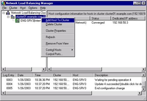
Right-click the cluster you want to add a node to in the left pane, and select Add Host To Cluster, as shown in Figure 19-8.
Enter the name or IP address of the host that will be joined to the cluster in the Connect screen, shown previously in Figure 19-6. Click Connect to connect to the server and bring up a list of network interfaces available. Select the interface that will host the public traffic of the cluster (as opposed to private, node-to-node traffic).
Click Next to bring up the Host Parameters screen, shown earlier in Figure 19-7. Here you set the priority for this host of the cluster and the dedicated IP address that will be used to connect to this specific server (as opposed to the cluster as a whole). This IP address must be a fixed IP address, not a DHCP address. Finally, set the initial state of this host when Windows is started.
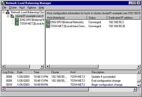
Click Finish to start up the NLB service on the new node and configure the server into the existing cluster. When the node is up and part of the cluster, it shows a status of Converged in the NLB Manager, as shown in Figure 19-9.
To remove a host from an NLB cluster, follow these steps:
Open the Network Load Balancing Manager from the Administrative Tools folder.
Connect to the cluster you want to remove a node from by right-clicking Network Load Balancing Clusters in the left pane and selecting Connect To Existing.
Right-click the node you want to remove in the left pane, and select Delete Host.
In general, an NLB cluster should contain as many hosts as needed to handle the client load for the applications being run in the cluster. The exception to this would be cases in which the sole function of the cluster is to provide failover tolerance for a critical TCP/IP application—that is, when a single server can handle the load and the second server is there simply for fault tolerance.
The maximum number of hosts in a given cluster is 32. If your application requires more than 32 hosts, you can set up multiple clusters, using round-robin DNS to distribute the load among the clusters. The effective limitation, however, is likely to be the network saturation point. If you do run multiple clusters in a subnet, you should host each on its own network switch to minimize the network bottleneck.
Although fewer and more powerful servers might look cost-effective for a given application, you should consider how the failure of a server will affect the application and the remaining servers. If the remaining servers can’t handle the resulting load, you could potentially have a cascading failure, bringing down the entire application. Always provide sufficient server capacity within the cluster to handle the expected load when a single server is down. Also consider ways to limit the load to the application when there has been a failure.
When determining the expected cluster capacity, you also need to consider the application being clustered and the type of load it imposes on the cluster. Plan your servers according to where the limitation and stress will be greatest. Web serving and FTP applications are input/output (I/O) intensive, whereas Terminal Services can be very CPU intensive, depending on the types of applications your user community uses.
Although NLB clusters provide overall fault tolerance for your TCP/IP application, they are not a complete solution for all possible failures. Because they are "shared nothing" clusters, there is always some data lag between servers. For fully fault-tolerant, high-availability clustering that can run any application, you should probably use server clustering, which provides the greatest level of fault tolerance.
One thing you can do to improve the overall fault tolerance of the cluster is to make the hard disks fault tolerant, whether physically attached to the server or as Network-Attached Storage (NAS). Both hardware and software RAID solutions are viable options for improving the fault tolerance of an NLB cluster. For more on RAID and fault tolerance in general, see Chapter 18 and Chapter 38.
Optimizing an NLB cluster calls for clearly understanding where the bottleneck in your clustered application is likely to be. An application such as a Web front end that is essentially a file server, for example, tends to be a heavy user of both disk I/O and network bandwidth, and such an application can be a RAM hog if you’re going to do effective caching. Terminal Services, on the other hand, can put a heavy load on the CPU, and to a somewhat lesser extent, on RAM, depending on your user community. Focus your optimization efforts on the bottleneck and you’ll get the most gain for your effort.
One area that can be a problem is running an NLB cluster in a switched environment without planning your network load carefully. If each of the servers in your cluster is connected to a different switched port, you can easily end up flooding your switched ports because every client request to the cluster passes through all switched ports to which a member of the cluster is attached. Running in multicast mode can exacerbate the problem. If you’re running in a switched environment, you should follow these guidelines:
Use a top-quality hub to connect the servers in the cluster to one another, and uplink the hub to a single switched port. If you do use switches, separate each cluster onto its own VLAN.
Use unicast mode. If you enabled multicast mode during setup, change it. (You’ll need to change this on all servers in the cluster.) It is possible to use multicast mode, but this requires enabling Internet Group Multicast Protocol (IGMP) support, introduced in Windows Server 2003. Given the other limitations multicast mode, however, unicast is preferred.
Edit the registry on each of the hosts in the cluster, changing the following key from the default parameter of 1 to 0:
HKEY_LOCAL_MACHINESystemCurrentControlSetServicesWLBS
  ParametersMaskSourceMAC
This change allows the switch to tell which MAC address is really the source of traffic, helping it to do its switching job properly. You’ll need to restart the servers after making this change.
A server cluster is a group of independent nodes that work together as a single system. They share a common cluster database that enables recovery in the event of the failure of any node. A traditional server cluster uses a jointly connected resource, generally a disk array on a shared SCSI bus or Fibre Channel, which is available to all nodes in the cluster. Each Windows Server 2003 Enterprise Edition node in the cluster must have access to the array, and each node in the cluster must be able to communicate at all times with the other nodes in the cluster.
Windows Server 2003 supports server clusters only on machines running Enterprise Edition or Datacenter Edition. Both editions support up to eight node clusters and can be configured in three different models: single node clusters, single quorum device clusters, and majority node set clusters. We focus on single quorum device clusters in this chapter. Single node clusters are primarily used for creating virtual servers and for proof of concept and development of cluster-aware applications. Majority node set server clusters require specialized support from both the hardware and software vendors involved.
To understand and implement server clusters, it is important to understand several new concepts and their ramifications, as well as specialized meanings for certain terms.
A cluster has two distinct types of networks: the private network that’s used to maintain communications between nodes in the cluster and the public network that clients of the cluster use to connect to the services of the cluster. Each of these networks can share the same network card and physical network cabling, but it is a good practice to keep them separate. This gives you an alternate path for interconnection between the nodes of the cluster. Because the interconnect between the nodes of a cluster is a potential single point of failure, it should always be redundant. The cluster service uses all available networks, both private and public, to maintain communications between nodes.
Real World: Always Have at Least Two Interconnects
If you have only a single method of communication in a cluster, the failure of that interconnect has a 50 percent chance (in a two-node cluster) of causing the entire cluster to become unavailable to its clients—hardly why you opted for a highly available technology like clustering. Here’s what happens when the nodes of a cluster can no longer communicate. When the communications fail, each node recognizes that it is no longer able to talk to the other nodes of the cluster and decides that the other nodes in the cluster have failed. Each node therefore attempts to take over the functions of the cluster by itself. The nodes are "partitioned," and as each node attempts to enable itself to take over the functions of the entire cluster, it starts by trying to gain control of the quorum resource (discussed later in the Types of Resources section) and, therefore, the shared disk on which the quorum resides. Because only one node is able to gain control of the quorum resource, the other nodes are automatically shut down while the single node attempts to maintain the processes of the cluster. However, because any given node has an equal chance of gaining control of the quorum resource, there’s a 50 percent chance in a two-node cluster that the node with a failed network card wins, leaving all the services of the cluster unavailable.
A node is a member of a server cluster. It must be running Windows Server 2003, Enterprise Edition or Windows Server 2003, Datacenter Edition, and Windows Clustering. It must also be running TCP/IP, be connected to the shared cluster storage device, and have at least one network interconnect to the other nodes in the cluster.
Groups are the units of failover. Each group contains one or more resources. Should any of the resources within the group fail, all fail over together according to the failover policy defined for the group. A group can be owned by only one node at a time. All resources within the group run on the same node. If a resource within the group fails and must be moved to an alternate node, all other resources in that group must be moved as well. When the cause of failure on the originating node is resolved, the group falls back to its original location, based on the failback policy for the group.
Any physical or logical entity that can be brought online or offline can be a server cluster resource. It must be able to be owned by only one node at a time and will be managed as part of the cluster. The quorum resource is a special resource that serves as the repository of the configuration data of the cluster and the recovery logs that allow recovery of the cluster in the event of a failure. The quorum resource must be able to be controlled by a single node, it must provide physical storage for the recovery logs and cluster database, and it must use the NTFS file system. The only resource type supported for a quorum resource in single quorum device clustering is the Physical Disk resource as shipped with Windows Server 2003 (which along with other resource types are described in the next section), but it is possible that other quorum resource types will be developed and certified by third parties.
Windows Server 2003 Enterprise Edition includes several resource types; the sections that follow examine each of these resource types and the role they play in a server cluster. The available cluster resource types are as follows:
Physical Disk
Dynamic Host Configuration Protocol (DHCP)
Windows Internet Naming Service (WINS)
Print Spooler
File Share
Internet Protocol Address
Local Quorum
Majority Node Set
Network Name
Generic Application
Generic Script
Generic Service
Volume Shadow Copy Service Task
The Physical Disk resource type is the central resource type required as a minimum for all server clusters. It is used for the quorum resource that controls which node in the cluster is in control of all other resources. The Physical Disk resource type is used to manage a shared cluster storage device. It has the same drive letter on all cluster servers.
The DHCP service provides IP addresses and various other TCP/IP settings to clients, and WINS provides dynamic resolution of NetBIOS names to IP addresses. Both can be run as a resource of the cluster, providing for high availability of these critical services to network clients. For failover to work correctly, the DHCP and WINS databases must reside on the shared cluster storage.
The Print Spooler resource type lets you cluster print services, making them fault tolerant and saving a tremendous number of help desk calls when the print server fails. It also ameliorates the problem of people simply clicking Print over and over when there’s a problem, resulting in a long and repetitious print queue.
To be clustered, a printer must be connected to the server through the network. Obviously, you can’t connect the printer to a local port such as a parallel or Universal Serial Bus (USB) port directly attached to one of the nodes of the cluster. The client can address the printer either by name or by IP address, just as it would a nonclustered printer on the network.
In the event of a failover, all jobs that are currently spooled to the printer are restarted. Jobs that are in the process of spooling from the client are discarded.
You can use a server cluster to provide a high-availability file server using the File Share resource type. The File Share resource type lets you manage your shared file systems in three different ways:
As a standard file share with only the top-level folder visible as a share name.
As shared subfolders, where the top-level folder and each of its immediate subfolders are shared with separate names. This approach makes it extremely easy to manage users’ home directories, for example.
As a standalone Distributed file system (Dfs) root. You cannot, however, use a cluster server File Share resource as part of a fault-tolerant Dfs root.
The Internet Protocol Address resource type is used to manage the IP addresses of the cluster. When an Internet Protocol Address resource is combined with a Network Name resource and one or more applications, you can create a virtual server. Virtual servers allow clients to continue to use the same name to access the cluster even after a failover has occurred. No client-side management is required because, from the client perspective, the virtual server is unchanged.
The Local Quorum resource type is used to manage the system disk on the local node of a single node server cluster. The Local Quorum resource type cannot fail over to another node.
The Majority Node Set resource type is used to manage cluster configuration data that might or might not reside on a cluster storage device. It is used to ensure that the data remains consistent across nodes that may be geographically dispersed. Only a single Majority Node Set resource can exist in a server cluster.
The Generic Application resource type allows you to manage regular, cluster-unaware applications in the cluster. A cluster-unaware application that is to be used in a cluster must, at a minimum:
Be able to store its data in a configurable location
Use TCP/IP to connect to clients
Have clients that can reconnect in the event of an intermittent network failure
When you install a generic, cluster-unaware application, you have two choices: you can install it onto the shared cluster storage, or you can install it individually on each node of the cluster. The first method is certainly easier because you install the application only once for the whole cluster. However, if you use this method you won’t be able to perform a rolling upgrade of the application, because it appears only once. (A rolling upgrade is an upgrade of the application in which the workload is moved to one server while the application on the other server is upgraded and then the roles are reversed to upgrade the first server.)
To give yourself the ability to perform rolling upgrades on the application, you need to install a copy onto each node of the cluster. You need to place it in the same folder and path on each node. This method uses more disk space than installing onto the shared cluster storage, but it permits you to perform rolling upgrades, upgrading each node of the cluster separately.
Similar to the Generic Application resource, the Generic Script resource type is used to manage operating system scripts as a cluster resource. The Generic Script resource type provides limited functionality.
Finally, server clusters support one additional type of resource—the Generic Service resource. This is the most basic resource type, but it does allow you to manage your Windows Server 2003 services as a cluster resource.
The Volume Shadow Copy Service Task resource type allows you to create jobs in the Scheduled Task folder that will be run against whatever node is currently hosting a particular resource group, allowing the task to fail over with the resource. As shipped, this resource type is used only to support Shadow Copies of Shared Folders in a server cluster.
Windows Server 2003 server clusters allow you to define the failover and failback (sometimes referred to as fallback) policies for each group or virtual server. This ability enables you to tune the exact behavior of each application or group of applications to balance the need for high availability against the overall resources available to the cluster in a failure situation. Also, when the failed node becomes available again, your failback policy determines whether the failed resource is immediately returned to the restored node, maintained at the failed-over node, or migrated back to the restored node at some predetermined point in the future. These options allow you to plan for the disruption caused when a shift in node ownership occurs, limiting the impact by timing it for off-hours.
When planning your server cluster, you’ll need to think ahead to what your goal is for the cluster and what you can reasonably expect from it. Server clusters provide for extremely high availability and resource load balancing, but you need to make sure your hardware, applications, and policies are appropriate.
The most common cluster configuration is static load balancing. In this scenario, the cluster is configured so that some applications or resources are normally hosted on one node whereas others are normally hosted on another node. If one node fails, the applications or resources on the failed node fail over to another node, providing high availability of your resources in the event of failure and balancing the load across the cluster during normal operation. The limitation of this configuration is that in the event of a failure, your applications will all attempt to run on fewer nodes, and you need to implement procedures either to limit the load by reducing performance or availability, or to not provide some less critical services during a failure. Another possibility for managing the reduced load-carrying capacity during a failure scenario is to have "at risk" users and applications that can be shut off or "shed" during periods of reduced capacity, much like power companies do during peak load periods when capacity is exceeded.
It’s important to quickly take steps to manage load during periods of failure when you configure your cluster for static load balancing. Failure to shed load can lead to catastrophic failure, or such extreme slowdown as to simulate it, and then no one will have access to the cluster’s resources and applications.
The cluster configuration with the highest availability and reliability for critical applications is to run one node of the cluster as a hot spare. This scenario requires that the hot spare node be sufficiently powerful to run the entire load of any other node in the cluster. You then configure all the applications and resources to run on the other nodes, with the one node sitting idle. In the event of failure on one of the primary nodes, the applications fail over to the idle node and continue with full capability. After the primary node is back online it can continue as the new hot spare, or you can force the applications back to the primary node, depending on the needs of your environment.
This scenario provides full and complete fault tolerance in the event of the failure of one of the nodes, but it has the greatest hardware cost. It also does not provide for full and complete fault tolerance in the event of multiple node failures—that would take essentially one hot spare for each primary node. Use this clustering configuration only where your applications or resources are critical and you can afford the extra hardware expense far more than any limits to the load in case of a failure.
Another cluster configuration is called load shedding or partial failover. In this configuration, critical applications and resources are designed to fail over to the other nodes in the cluster in the event of a failure, but noncritical applications and resources are unavailable until the cluster is back to full functionality. The critical resources and applications are thus protected in a failure situation, but noncritical ones simply run as though they were on a stand-alone server.
In this configuration, you might, depending on capacity and load conditions, have to configure the noncritical applications and resources on all nodes to be unavailable in the event of a failure on other nodes. This allows you to maintain a high level of performance and availability for your most critical applications while shedding the load from less critical applications and services when necessary. This strategy can be very effective when you must, for example, service certain critical applications or users under any and all circumstances but can allow other applications and users with a lower priority to temporarily fail.
You can create a server cluster that has only a single node, which allows you to take advantage of the virtual server concept to simplify the management and look of the resources on your network. For example, the File Share resource lets you create automatic subdirectory shares of your primary share and control their visibility, a perfect way to handle users’ home directories. Having a single node doesn’t give you any additional protection against failure or any additional load balancing over that provided by simply running a single standalone server, but it allows you to easily manage groups of resources as a virtual server.
This scenario is an effective way to stage an implementation. You create the initial virtual server, putting your most important resources on it in a limited fashion. Then, when you’re ready, you add another node to the server cluster and define your failover and fail-back policies, giving you a high-availability environment with minimal disruption to your user community. In this scenario, you can space hardware purchases over a longer period while providing services in a controlled test environment.
Capacity planning for a server cluster can be a complicated process. You need to thoroughly understand the applications that will be running on your cluster and make some hard decisions about exactly which applications you can live without and which ones must be maintained under all circumstances. You’ll also need a clear understanding of the interdependencies of the resources and applications you’ll be supporting.
The first step is to quantify your groups or virtual servers. Applications and resources that are in the same group will fail over together onto the same server. This means you’ll need to plan out which applications are dependent on each other and will need to function together. Make a comprehensive list of all applications in your environment, and then determine which ones need to fail over and which ones can be allowed to simply fail but still should be run on a virtual server.
Next, determine the dependencies of the applications and the resources they need to function. This allows you to group dependent applications and resources in the same group or virtual server. Keep in mind that a resource can’t span groups, so if multiple applications depend on a resource, such as a Web server, they must all reside in the same group or on the same virtual server as the Web server and thus share the same failover and failback policies.
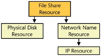
A useful mechanism for getting a handle on your dependencies is to list all your applications and resources and draw a dependency tree for each major application or resource. This helps you visualize not only the resources that your application is directly dependent on, but also the second-hand and third-hand dependencies that might not be obvious at first glance. For example, a cluster that is used as a high-availability file server uses the File Share resource. And it makes perfect sense that this File Share resource is dependent on the Physical Disk resource. It’s also dependent on the Network Name resource. However, the Network Name resource is dependent on the IP Address resource. Thus, although the File Share resource isn’t directly dependent on the IP Address resource, when you draw the dependency tree you will see that they all need to reside in the same group or on the same virtual server. Figure 19-10 illustrates this dependency tree.
Finally, as you’re determining your cluster capacity, you need to plan for the effect of a failover. Each server must have sufficient capacity to handle the additional load imposed on it when a node fails and it is required to run the applications or resources owned by the failed node.
The disk capacity for the shared cluster storage must be sufficient to handle all the applications that will be running in the cluster and to provide the storage that the cluster itself requires for the quorum resource. Be sure to provide enough RAM and CPU capacity on each node of the cluster so that the failure of one node won’t overload the other node to the point that it too fails. This possibility can also be managed to some extent by determining your real service requirements for different applications and user communities and reducing the performance or capacity of those that are less essential during a failure. However, such planned load shedding might not be sufficient and frequently takes a significant amount of time to accomplish, so give yourself some margin to handle that initial surge during failover.
Once you’ve thoroughly researched and planned your implementation of server clusters, you’re ready to actually create the cluster. The mechanism to create and manage server clusters is the Cluster Administrator application, part of the Administrative Tools folder.
To create a new server cluster, follow these steps:
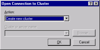
Open the Cluster Administrator from the Administrative Tools folder. Select Create New Cluster from the drop-down list in the Open Connection To Cluster dialog box, as shown in Figure 19-11.
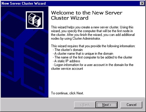
Click OK to launch the New Server Cluster Wizard, shown in Figure 19-12. The New Server Cluster Wizard walks you through testing to see if the cluster can be successfully created. It also gives you an opportunity to correct issues it discovers during the test, and then actually creates the cluster.
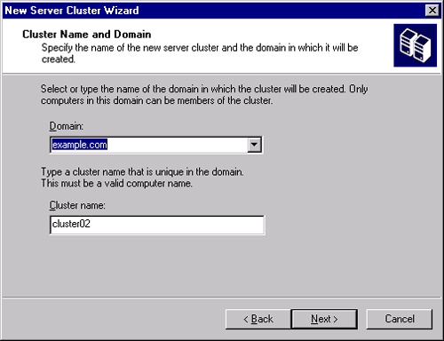
Click Next to bring up the Cluster Name And Domain page, as shown in Figure 19-13. The domain is generally already filled in with the current domain. Fill in the name for the cluster. You can make this a name that means something to you, as opposed to your user community, because you’ll likely be creating virtual servers for it.
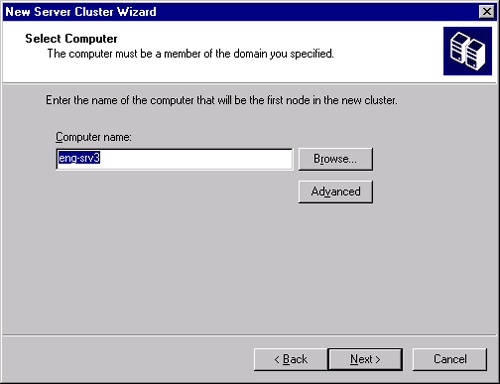
Click Next to bring up the Select Computer page, shown in Figure 19-14. Enter the name of the computer that will be the first computer in the new cluster in the Computer Name field.
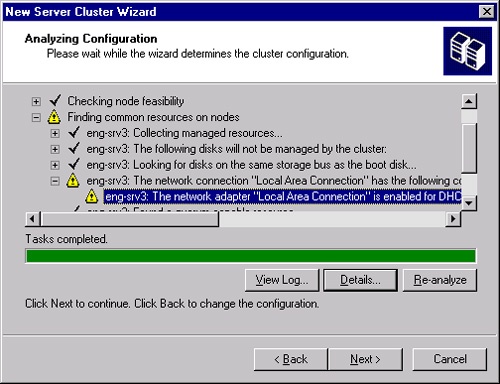
Click Next to bring up the Analyzing Configuration page. The wizard automatically analyzes the configuration and highlights any problems, as shown in Figure 19-15. If the bar is green, the problems it found are nonfatal and you could go ahead and create the cluster. However, you should attempt to correct any problems before proceeding.
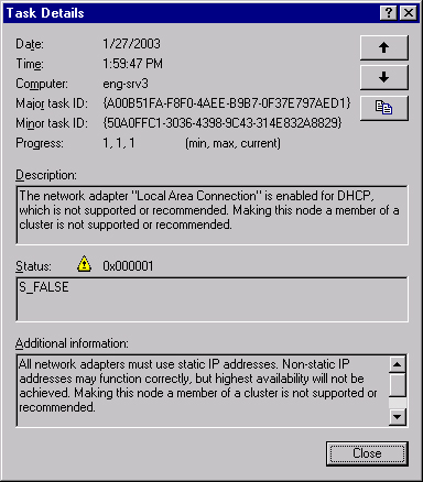
To view details on the problems found, click View Log. A typical problem is shown in Figure 19-16. You can correct the problem (in this case, one of the network adapters was configured for DHCP, a nonrecommended configuration) and then click Re-analyze to run the analysis again.
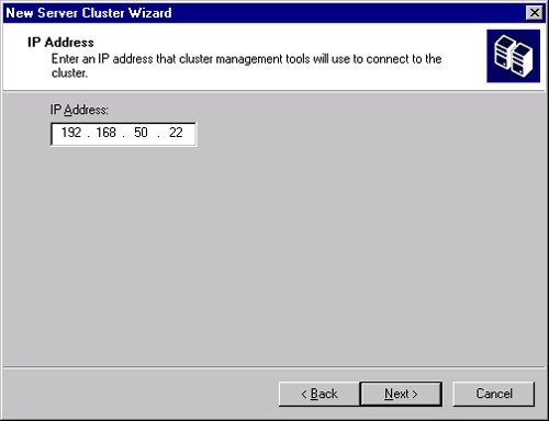
Once the Analyzing Configuration Wizard gives you a clean bill of health, click Next to open the IP Address page, shown in Figure 19-17. Enter the IP address that will be used by clustering management tools to connect to the cluster.
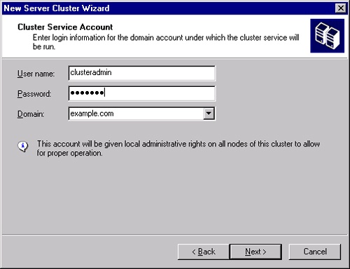
Click Next to bring up the Cluster Service Account page shown in Figure 19-18. This can be an existing account or a new account. The account will be given local administrative privileges on all nodes of the cluster. Click Next.
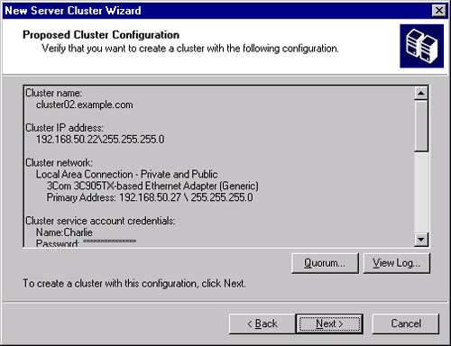
The final confirmation page is shown in Figure 19-19. Spend a moment here to verify that this is really what you want to do and that everything agrees with your checklist. You can go back and fix anything before continuing, if necessary, so take the time now.
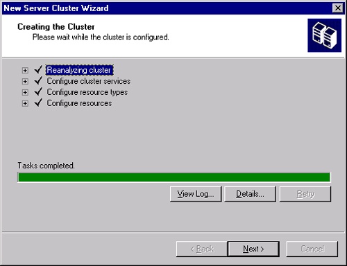
When you’re ready, click Next to start creating the cluster. When the process is complete, you’ll see a status page as shown in Figure 19-20. Click View Log to see a log of the process, or click Details to see more detailed steps than those shown. If there were problems, you’ll be able to go back and correct them and try again. Click Next.
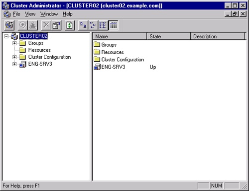
This brings you to the final page of the New Server Cluster Wizard. You can view the log from here by clicking View Log or change from Local Quorum to Majority Node Set by clicking the Quorum button. Click Finish and the New Server Cluster Wizard exits, leaving you in the Cluster Administrator application, as shown in Figure 19-21.
Once you have your cluster created, you can take advantage of the management capabilities of Cluster Administrator to create cluster resources. We’ll walk through the steps to create a File Share cluster resource in a new group on a virtual server called HOME. Referring to Figure 19-10, you’ll see the list of dependencies we need to deal with. Although we could put these resources in the main Cluster group, we prefer to group items into more logical units, especially because failover policies are controlled at the group level. Therefore, to create our File Share resource, we’ll need to do the following:
Create a group to hold the necessary resources
Create a Physical Disk resource
Create an IP Address resource
Create a Network Name resource
Create the File Share resource
To create a new cluster group, follow these steps:
Open the Cluster Administrator from the Administrative Tools folder, and connect to the cluster where you will be creating the resource.
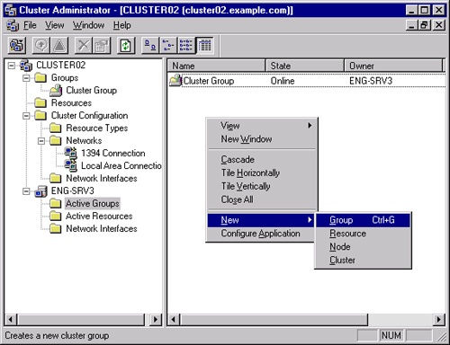
Right-click the Active Groups folder of the server that will host the File Share resource, and select Group from the New menu, as shown in Figure 19-22.
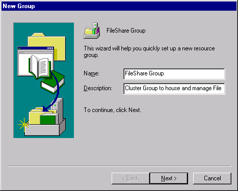
This opens the New Group Wizard shown in Figure 19-23. Give your new cluster group an appropriate name and description.
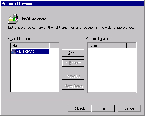
Click Next to bring up the Preferred Owners dialog box shown in Figure 19-24. This allows you to control which nodes are the preferred owners of this share, and the order of preference. Select the nodes to be used for this group, and click Add to move them to the right pane. Use the Move Up and Move Down buttons to arrange their order of precedence.
Click Finish to create the group. The group is created and is initially offline, because it has no active resources associated with it.
To create a new Physical Disk resource, continue with the following steps:
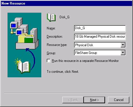
Right-click the group just created and select Resource from the New menu to open the New Resource Wizard, shown in Figure 19-25.
Fill in the Name and Description fields, and select Physical Disk from the Resource Type drop-down list. The Group should be the one you just created.
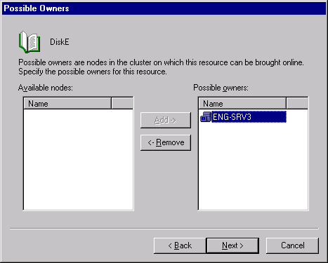
Click Next to open the Possible Owners page, as shown in Figure 19-26. Specify which machines in the cluster can host this resource.
Click Next to open the Dependencies page. This will be blank because this is the first resource in this group.
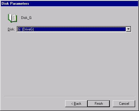
Click Next to open the Disk Parameters page, shown in Figure 19-27. The Disk drop-down list will include all Physical Disk resources that can be managed by the cluster service.
Select the disk that will be the Physical Disk resource, and click Finish to create the resource.
To add a new IP address resource, continue with the following steps:
Right-click the group just created and select Resource from the New menu to open the New Resource Wizard, shown earlier in Figure 19-25.
Fill in the Name and Description fields, and select File Share from the Resource Type drop-down list. The Group should be the one you just created.
Click Next to open the Possible Owners page, shown earlier in Figure 19-26. Specify which machines in the cluster can host this resource.
Click Next to open the Dependencies page. This will have the Physical Disk resource we just created, but referring to our dependency tree in Figure 19-10, we see that there is no dependency for the IP Address resource type.
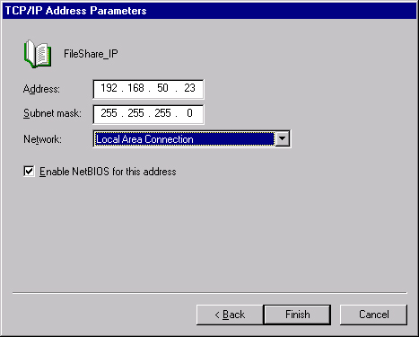
Click Next to open the TCP/IP Address Parameters page, shown in Figure 19-28. Fill in the IP address and parameters that will be used for this share.
Click Finish to create the IP Address resource.
To add a new network name resource, continue with the following steps:
Right-click the group just created and select Resource from the New menu to open the New Resource Wizard shown earlier in Figure 19-25.
Fill in the Name and Description fields, and select Network Name from the Resource Type drop-down list. The Group should be the one you just created.
Click Next to open the Possible Owners page, shown earlier in Figure 19-26. Specify which machines in the cluster can host this resource.
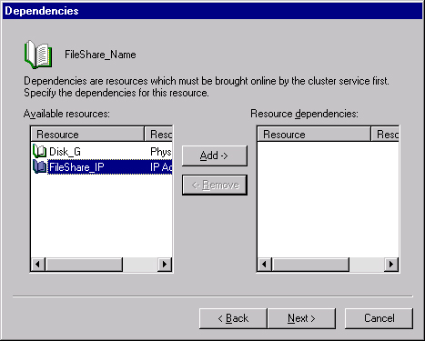
Click Next to open the Dependencies page, shown in Figure 19-29. We’ll now see both the Physical Disk and IP Address resources on the list of available resources. By looking at the dependency tree, we see that the Network Name resource has a dependency on the IP Address resource, so select the IP Address resource in the left plane and click Add to move it to the right dependencies pane.
Click Next to open the Network Name Parameters page, and enter the name for the virtual server.
Click Finish to create the Network Name resource.
Finally, we’re ready to create the File Share resource, because we’ve made all the dependencies.
Right-click the group just created and select Resource from the New menu to open the New Resource Wizard shown earlier in Figure 19-25.
Fill in the Name and Description fields, and select IP Address from the Resource Type drop-down list. The Group should be the one you just created.
Click Next to open up the Possible Owners page, shown earlier in Figure 19-26. Specify which machines in the cluster can host this resource.
Click Next to open the Dependencies page. We’ll now see all three of the resources we’ve just created. We know that all of them are required for the File Share resource to work, so we’ll move them all to the rightmost dependency pane.
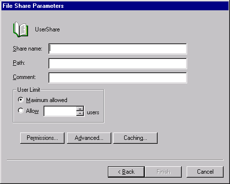
Click Next to open the File Share Parameters page shown in Figure 19-30.
Fill in the Share Name and Path fields, and add a description in the Comment text box. If you click Finish now, you’ll end up with a simple File Share.
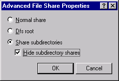
Click Advanced to open the Advanced File Share Properties dialog box shown in Figure 19-31. Select Share Subdirectories and Hide Subdirectory Shares, and click OK.
Click Finish to create the File Share resource, and click OK to acknowledge the success.
Finally, right-click the group you created and select Bring Online to make the resource actually online and available.
As this edition of the book is being written, Microsoft is beta testing a new kind of Windows Server clustering—High Performance Computing (HPC) clusters, also called compute clusters. Unlike NLB or server clusters, compute clusters are not designed to provide high availability for critical applications, but rather to distribute highly parallel and complex computing tasks across multiple nodes. Windows Compute Cluster Server 2003 (CCS) enables super-computer functionality on the desktop.
CCS is a combination of a special version of Windows Server 2003 x64 Edition; the Compute Cluster Edition (CCE); and a package of interfaces, management tools, and utilities known as the Compute Cluster Pack. The Compute Cluster Pack is available separately and can be installed on any x64 Edition of Windows Server 2003, including R2 versions. CCE is at the SP1 level and does not support installation of R2.
Note
Windows Compute Cluster Server 2003 is supported only on x64 Editions of Windows Server 2003. It is not available on 32-bit Windows Server 2003, nor on Itanium 64-bit editions.
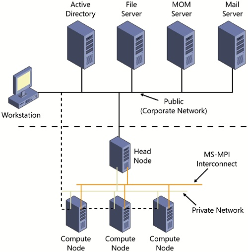
CCS supports configurations that have one, two, or three NICs per node. The preferred configuration is a head node with a public (internal network LAN) interface, a private intra-cluster communications interface, and a high-speed Message Passing Interface (MPI). Each compute node in the cluster would have at least a private communications interface and the MPI interface. Figure 19-32 shows this topology.
CCS includes Remote Installation Services (RIS) that allows the easy setup and deployment of compute nodes on demand. Once the head node is created and configured, individual compute nodes are simply connected to the network and powered up. RIS then deploys Windows Server 2003 Compute Cluster Edition to the new node and configures it to be part of the compute cluster.
CCS includes the Microsoft Message Passing Interface (MS MPI), a highly compatible implementation of the Argonne National Labs MPICH2 specification. Because the MS MPI implementation is completely compatible with MPICH2 at the API level, existing HPC applications that use MPICH2 will easily migrate to CCS.
More Info
For additional information on CCS, including details of MPI, migration of existing parallel applications, and parallel debugging, see http://www.microsoft.com/windowsserver2003/ccs/default.mspx.
Windows Server 2003, Enterprise Edition provides two high-availability clustering models: Network Load Balancing clusters (formerly known as the Windows Load Balancing Service) and server clusters. Clusters provide a highly available and scalable environment. Network Load Balancing clusters use standard hardware to distribute TCP/IP applications across a cluster. Server clusters use specialized shared disk resources to provide failover and static load balancing for a variety of applications. A new type of Windows Server 2003 cluster, the compute cluster, supports high-performance computing and highly parallel computing tasks. The next chapter covers configuring your storage as well as planning for fault tolerance and flexibility in managing your storage needs.