
Chapter 6
Hydrodynamic Flow Confinement-Assisted Immunohistochemistry from Micrometer to Millimeter Scale
Robert D. Lovchik, David P. Taylor, Emmanuel Delamarche and Govind V. Kaigala
IBM Research – Zurich, Säumerstrasse 4, 8803 Rüschlikon, Switzerland
In this chapter, we outline the importance of immunohistochemical analysis applied to tissue sections and review the state-of-the-art IHC implementations, in particular those using a microfluidic probe. We demonstrate the efficacy and applicability of specific probe head designs in the context of surface assays by performing uniform and multiplexed immunohistochemistry on tissue sections in the micrometer to millimeter scale.
6.1 Immunohistochemical Analysis of Tissue Sections
IHC, a staining process based on specific antibody–antigen binding, is widely used in pathology to detect disease markers in tissue sections. This staining method is used for visualizing the level of expression of specific markers in tissues to identify the type and stage of diseases. It is also typical that a counterstaining (e.g., unspecific staining of nuclei or cell membranes) is applied for better contrast in the morphological characterization of the tissue (histology). Pathologists who routinely perform IHC need to screen biopsy samples for multiple disease markers to subtype and personalize treatment strategies. Some of the challenges they regularly encounter are the limited amounts of tissue sample, the qualitative nature of the staining results, and the need for human interpretation of complex IHC outcomes, which impact the life of patients [1]. Therefore, methods that can extract more information from tissues and provide increased flexibility in IHC staining procedures are needed.
A flexible method to extract more high-quality information from tissue sections is critically needed for both drug discovery and clinical pathology. Recent attempts to increase the amount of information retrieved from tissues are (i) simultaneous incubation with multiple antibodies, which is limited by cross-reactivity; (ii) the use of a double immuno-enzymatic reaction, which results in increased background; and (iii) the use of multiple enzymatic substrates, which requires elaborate processing [1]. Multiple antibodies labeled with quantum dots have also been used, but the antibody cross-reactivity persisted [2]. Gannot et al. [3] developed a technique, termed layered IHC, wherein several membranes were placed on a tissue section and incubated with antibodies. The immunoblotted antigens were then detected on specific membranes. This approach, while suitable for multiplexing, is tedious, uses the entire tissue section, and does not provide a path forward for interactive optimization of staining conditions. Sun et al. [4] dislocated solid tumors and placed them in isolated chambers for immunocytochemistry. This approach, while suitable for systems biology analysis, does not provide histological information about the tissue. A clever demonstration to perform localized IHC in microchannels was reported by Kim et al. [5], but flushing reagents within microchannels sealed on tissue sections limits the flexibility to only staining specific regions of interest on the tissue section. Such microchannel approaches have also been used for brain slice microenvironment modification [6] and large area tissue section IHC using multiple streams of liquid [7] and in combination with lanthanide-based immunocomplexes [8].
Localizing liquids on surfaces is critical for performing micrometer-scale IHC. Liquid localization has been pursued using AFM cantilevers [9], scanning electrochemical microscopy [10], nanopipettes [11], a chemistrode [12], and a polymeric two-phase system [13]. While these techniques have been demonstrated in the context of specific applications, they are not suitable for noncontact processing of tissues and do not provide flexibility in scanning tissues at the length scales needed.
A promising technology for local interaction with immersed substrates is the microfluidic probe (MFP) and its variants [14–16]. The MFP operates in a noncontact scanning mode and localizes a liquid on a surface by creating a hydrodynamic flow confinement (HFC). We developed a scanning noncontact microfluidic technology, which confines picoliters of liquids on a surface of interest, and have shown that it can add and remove proteins from surfaces as well as inactivate and detach adherent cells [14, 16]. The MFP and its variants have been applied for multiplexed immunohistochemical analysis of tissue sections [17], biopatterning [18], pharmacology on a single cell level [19], microperfusion on brain slices [20], and lysis of adherent cell layers for messenger RNA analysis [21].
6.2 Probe Heads for Multiscale Surface Interactions
The main component of the MFP is the head, a microfluidic device that has apertures at its apex to inject and aspirate liquids at a distance of 1–30 µm from the sample surface. This head is mounted on a stage that can scan areas with micrometer resolution up to the size of a microscope glass slide (1 in. × 3 in.), thereby enabling custom and precise patterning of biomolecules on biological interfaces. More details about the working principle of MFPs can be found in Chapter 1 of this book. Here, we present a family of microfluidic probe devices along with a methodology for selective delivery of microliter volumes of processing liquids to immersed substrates on the millimeter to centimeter length scales. This enables new strategies for multiplexed surface-based assays: uniform, localized exposure to a single reagent, multiplexed exposure to several reagents, and gradients of several reagents. For millimeter-scale interactions with surfaces, we present two families of probes, one with slit-aperture designs for interacting with a surface using a single reagent and creating concentration gradients and the second one with aperture-array designs for multiplexed interaction and for creating concentration gradients (Figure 6.1).
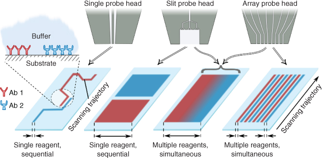
Figure 6.1 Strategies of interacting with immersed substrates on the millimeter to centimeter scale using hydrodynamic flow confinement. Two families of probes, slit-aperture probes and aperture-array probes, enable several strategies of interfacing with surfaces: sequential exposure (left), multiplexed exposure to different reagents on spatially separated regions (right), and creation of gradients (center). Inset: Schematic of antibodies patterned on a substrate immersed in physiological buffer.
6.2.1 Probe Design and Operating Conditions for Millimeter-Scale HFCs
Two-layer Si/glass probe heads allow the formation of a micrometer-scale drop-shaped HFC by simultaneously injecting and aspirating a processing liquid between adjacent apertures at the apex (Figure 6.2a) [16]. Extending the HFC in one dimension can potentially enable processing on the centimeter scale by scanning in the direction perpendicular to the direction of extension. Intuitively, one would design probes with increased spacing between the two adjacent apertures, resulting in an HFC that is elongated along its main axis. This, however, is not a viable approach for the following reasons: (i) The resulting HFC would be significantly broad in the proximity of the injection aperture and rather narrow in the proximity of the aspiration aperture (a “stretched” drop shape). This change in width would result in nonuniform incubation times at different positions of the HFC, and would become prominent when scanning the substrate in the direction perpendicular to the direction of extension (main axis of the HFC; Figure 6.2a), (ii) to realize HFC at “reasonable” flow rates (![]() ), the distance between adjacent apertures may not be larger than the shortest distance between an aperture and the edge of the apex. The maximum spacing between the adjacent apertures is therefore limited to the thickness of the glass and Si substrates.
), the distance between adjacent apertures may not be larger than the shortest distance between an aperture and the edge of the apex. The maximum spacing between the adjacent apertures is therefore limited to the thickness of the glass and Si substrates.
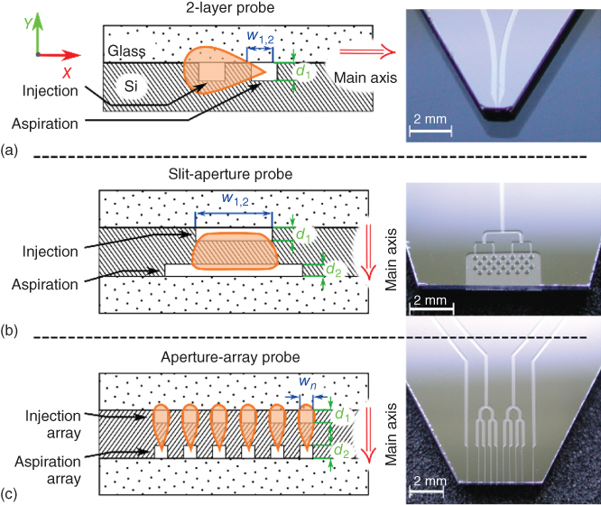
Figure 6.2 Design of slit-aperture and array probes. (a) Left: Schematic of a two-layer probe with channels etched on the face of the silicon substrate and then covered by glass. Aperture designs are restricted to linear configurations with a common etch depth, d. Right: Photograph of a two-layer probe with two channels leading to the apex. (b) Left: Schematic of a slit-aperture probe for creating a homogeneous HFC, which is scalable in one dimension (along the X-axis). Right: Photograph of a slit-aperture probe. Channels connecting to slit apertures are bifurcated to provide a homogeneous distribution of the flow through the aperture. (c) Left: Schematic of an aperture-array probe for creating parallel HFCs. Right: Photograph of the aspiration side of an aperture-array probe. While the injection apertures are addressed independently, the aspiration apertures are grouped to minimize external fluidic interconnects.
Another approach to enlarging the HFC is to increase the dimensions of the apertures perpendicularly to the main axis of the HFC. In a two-layer probe, this can be done by increasing the etch depth d, which is, also, limited by the thickness of the Si substrate. We note that fabrication techniques with different materials, for example, plastics, might provide additional options for scaling of the apertures. However, in the context of biological assays, probes in Si and glass offers several advantages, such as (i) high-resolution features and geometries, (ii) chemical inertness, (iii) robust thermomechanical properties, (iv) good optical properties, (v) controllable surface properties, and (vi) robust and established protocols for fabrication and quality control [16]. To enable scaling of the apertures while leveraging the advantages of Si/glass probes, we developed a three-layer probe design, which allows the main axis of the HFC to be oriented perpendicularly to the Si and glass layers (Figure 6.2b). In such a design configuration, the HFC can be extended homogeneously in one dimension by scaling w. Also, w can be varied independently for each aperture, and scaling is independent of the thicknesses of the Si and glass substrates. This allows the fabrication of probes with adjacent slit apertures (Figure 6.2b) or arrays of adjacent apertures (Figure 6.2c).
6.2.2 Slit-Aperture Probes
We performed numerical simulations of liquid flow in the gap between the probe and the substrate to study and optimize the flow patterns generated by slit-aperture probes (Figure 6.3a,b). We fixed the distance between the probe and the substrate at 30 µm and ![]() . The simulation results suggest that for a design with identical slit lengths and an aspiration flow rate higher than the injection flow rate, a sheath flow of immersion liquid prevents the confined processing liquid from contacting the substrate. These failure modes, however, can be avoided by designing the aspiration aperture to be longer than the injection aperture. We performed numerical analysis of the flow conditions for a probe with apertures with a length ratio of
. The simulation results suggest that for a design with identical slit lengths and an aspiration flow rate higher than the injection flow rate, a sheath flow of immersion liquid prevents the confined processing liquid from contacting the substrate. These failure modes, however, can be avoided by designing the aspiration aperture to be longer than the injection aperture. We performed numerical analysis of the flow conditions for a probe with apertures with a length ratio of ![]() . With the ratio of flow rates remaining at
. With the ratio of flow rates remaining at ![]() , significantly less liquid is aspirated from the direction of the injection aperture, and the injection flow is not smaller than the aspiration flow in the vicinity of the injection aperture. This results in the formation of a stagnation zone between the edge of the apex and the injection aperture, indicating that no sheath flow of immersion liquid is formed and thus the confined processing liquid makes contact with the surface.
, significantly less liquid is aspirated from the direction of the injection aperture, and the injection flow is not smaller than the aspiration flow in the vicinity of the injection aperture. This results in the formation of a stagnation zone between the edge of the apex and the injection aperture, indicating that no sheath flow of immersion liquid is formed and thus the confined processing liquid makes contact with the surface.
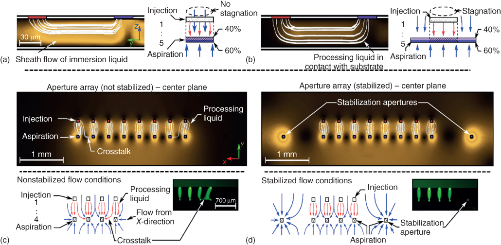
Figure 6.3 Optimization of slit and aperture probe designs and operating parameters. (a) Numerical simulation of relative amplitude of flow velocity (zero flow velocity in black regions, high flow velocity in bright regions) and flow pattern of injected processing liquid (white streamlines) in the vertical center plane for a probe design with slit apertures of identical length. (b) A slit probe design with an aspiration aperture that is 4× longer than the injection aperture. No sheath flow of immersion liquid is formed. (c) Top: Numerical simulation of relative amplitude of flow velocity (zero flow velocity in black regions, high flow velocity in bright regions) and the flow pattern of processing liquid (white streamlines) in the center plane between probe and substrate for an aperture array without stabilization. Bottom: Nonsymmetric conditions for the aspiration apertures at the extremities of the array lead to cross-talk between HFCs. (d) Top: Additional stabilization apertures can suppress the cross-talk between single flow confinements. Bottom: Stabilization apertures allow the creation of symmetric conditions for the aspiration apertures at the extremities of the array. Insets: Photographs of arrays of flow confinements using a fluorescein-spiked processing liquid with and without stabilization apertures.
A longer aspiration aperture also ensures a stable confinement of the processing liquid over a broader range of Qi/Qa values, because on both sides of the injection aperture, there is still flow of immersion liquid from the upper edge of the apex. This results in a shielding flow of immersion liquid around the HFC that improves the stability of the confinement.
6.2.3 Aperture-Array Probes
An array of HFCs enables multiplexed and simultaneous processing of a substrate with different reagents. Numerical analysis of the flow patterns in the XY-plane (gap distance 30 µm, ![]() ) suggests that in such a probe design, there can be cross-talk between the HFCs at the extremities of the array and their adjacent HFCs (Figure 6.3c). The aspiration apertures for the HFCs at the extremities of the array can aspirate liquid from the X-direction. This is not the case for the other aspiration apertures in the array, as there are competing aspiration apertures on both sides in the X-direction, resulting in a stagnation of flow between neighboring apertures. The additional flow to the aspiration apertures at the edges of the array results in less liquid being aspirated from the direction of the respective injection apertures. A fraction of the processing liquid injected at the extremities of the array is therefore aspirated by the neighboring aspiration apertures, which alters the adjacent HFC, albeit to a lesser extent. A solution to this problem is to create flow conditions for the HFCs at the extremities of the array that mimic the conditions within the array. This can be achieved by including additional aspiration-only apertures beyond the extremities of the array in the X-direction, which we term stabilization apertures (Figure 6.3d). These stabilization apertures suppress flow from the X-direction to the aspiration apertures of the flanking HFCs, resulting in stagnating flow between the stabilization apertures and the aspiration apertures at the extremities of the array. Those aspiration apertures therefore aspirate mainly from the Y-direction, which leads to a stronger aspiration and therefore a better confinement of the respective processing liquids. The cross-talk between HFCs and also the efficacy of the stabilization apertures for averting cross-talk were experimentally verified and are in concordance with numerical simulations.
) suggests that in such a probe design, there can be cross-talk between the HFCs at the extremities of the array and their adjacent HFCs (Figure 6.3c). The aspiration apertures for the HFCs at the extremities of the array can aspirate liquid from the X-direction. This is not the case for the other aspiration apertures in the array, as there are competing aspiration apertures on both sides in the X-direction, resulting in a stagnation of flow between neighboring apertures. The additional flow to the aspiration apertures at the edges of the array results in less liquid being aspirated from the direction of the respective injection apertures. A fraction of the processing liquid injected at the extremities of the array is therefore aspirated by the neighboring aspiration apertures, which alters the adjacent HFC, albeit to a lesser extent. A solution to this problem is to create flow conditions for the HFCs at the extremities of the array that mimic the conditions within the array. This can be achieved by including additional aspiration-only apertures beyond the extremities of the array in the X-direction, which we term stabilization apertures (Figure 6.3d). These stabilization apertures suppress flow from the X-direction to the aspiration apertures of the flanking HFCs, resulting in stagnating flow between the stabilization apertures and the aspiration apertures at the extremities of the array. Those aspiration apertures therefore aspirate mainly from the Y-direction, which leads to a stronger aspiration and therefore a better confinement of the respective processing liquids. The cross-talk between HFCs and also the efficacy of the stabilization apertures for averting cross-talk were experimentally verified and are in concordance with numerical simulations.
6.3 Immunohistochemistry with Microfluidic Probes
Using a microfluidic probe, nanoliters of antibody solutions are confined over micrometer-sized areas of tissue sections for their incubation with primary antibodies, the key step in conventional IHC. We present a flexible method to perform IHC on tissue sections at the micrometer scale and using multiple antibodies; we call this method micro-immunohistochemistry (µIHC).
The implementation of the MFP for µIHC is in line with the standard workflows used in conventional IHC (Figure 6.4). The MFP head is compatible with (bio)chemical systems used for staining, is resistant to a broad range of chemicals, and can be used indefinitely unless physically damaged. Its rhombic shape and its small apex (1 mm2 or less in area) enable easy viewing of tissue sections both from above for positioning the MFP and from underneath using an inverted microscope for quantitative measurements. For staining, we make use of a commonly used enzymatically amplified staining with the chromogen 3,3′-diaminobenzidine (DAB), which can be visualized in bright field. The presence of an immersion liquid around the apex, in addition to enabling confinement of the processing liquid, prevents drying artifacts.
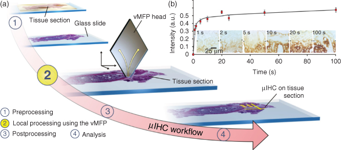
Figure 6.4 Concept and workflow of µIHC using a MFP. (a) Dewaxing and rehydration of the tissue are performed according to conventional IHC (1). Using injection and aspiration apertures at the apex of a MFP head, a solution of primary antibody is hydrodynamically confined (in the presence of an immersion liquid) to selected areas of a tissue section (2). Postprocessing for visualization of the antigens on the tissue section continues as in standard IHC: the tissue section is incubated with secondary antibodies, and enzymatic precipitation of DAB chromogen leads to a visual signal, indicating the expression level of specific antigens in the tissue section semiquantitatively. Typical parameters for the MFP scans are indicated. (b) Interaction of a processing liquid with tissue sections. Multiple regions of a normal human thyroid tissue section were incubated with a 700 µg/mL solution of α-TGB in PBS Tween 20 for various residence times. The staining intensities for residence times between 1 and 100 s are shown in the graph. The marks in the micrographs indicate the boundary between stained (lower half) and unstained regions (upper half).
The interaction of the confined processing liquid of the MFP with the tissue section is critical and has therefore been assessed for an extended duration. The footprint of the confined liquid on the tissue is comparable to the areas examined using laser capture microdissection [22], a technique widely used to isolate cells from tissue sections. Here, the difference is that vertical microfluidic probe (vMFP)-based µIHC preserves the tissue integrity for histological studies. Several factors together define the achievable level of staining. Some of these are intrinsic to the biological system such as the receptor–ligand binding kinetics, the expression level of the antigen, and the tissue morphology. Because the flow confinement is highly stable, it is straightforward to vary the residence time of the primary antibody solution on the tissue section to cover a large spectrum of antigen–antibody reaction times.
A human anti-thyroglobulin antibody (α-TGB) was delivered in approximately 100 µm wide lines across a healthy human thyroid tissue, and as expected, a correlation between the incubation time and the signal intensity was observed (Figure 6.4b). This correlation reveals that specific interactions between antigen and antibodies from various tissues can be adjusted by varying the residence time. In the experiment, the incubation time of thyroid tissue with α-TGB was tested to achieve clear staining and was on the order of 20 s for the conditions used in the experiment. This duration is considerably shorter than the 30 min recommended by the supplier for standard IHC. We attribute this reduction in incubation time to convection, which resulted in increased transport of primary antibodies. While this reduction in processing time can be antibody dependent, we do not know whether it will always exist because some markers may not be as accessible as others. The mechanical interaction between the injected liquid and the tissue may also improve the transport of molecules within the tissue.
6.4 Micro-IHC on Human Tissue Sections
µIHC was performed on invasive ductal carcinoma breast tissue using an antibody (α-p53) against the tumor suppressor protein p53. The two spots shown in Figure 6.5a were processed with an MFP residence time of approximately 500 s. We also performed multiplexed µIHC with two antibodies, α-p53 and anti-progesterone receptor (α-PR), by manually exchanging the syringes containing different antibody solutions. As a control, conventional staining was performed following a similar IHC protocol. Counterstaining trajectories close to the µIHC spots were done with hematoxylin and a residence time of 1 s (Figure 6.5b).

Figure 6.5 µIHC on cancerous breast tissue sections using different antibodies. (a) Monoplex staining of a 4 µm thick well-differentiated invasive ductal carcinoma breast tissue section using a monoclonal mouse antihuman p53 protein antibody (54 µg/mL, residence time 200 s). A line of hematoxylin is patterned with 1 s residence time for counterstaining. (b) Multiplexed staining of a well-differentiated invasive ductal carcinoma breast tissue section for the presence of p53 (α-p53: 54 µg/mL, residence time of 300 s) and human progesterone receptor (PR) (α-PR: 125 µg/mL, residence time of 300 s) with an additional hematoxylin counterstain.
6.4.1 Micro-IHC on Tissue Microarrays
The need for multiplexing and making more efficiently use of tissue sections is even more pressing when performing tests with tissue microarrays (TMAs). TMAs represent an interesting format in which only millimeter-sized tissue section cores are used to screen for new biomarkers [23] while providing sufficient information for the reliable evaluation of specimens, including that of cancerous breast tissue [24].
Given the increasing use of TMAs, processing of small areas within individual cores of TMAs was performed. We screened four cores of an infiltrating breast cancer TMA for the presence of three targets: estrogen receptor (ER), PR, and p53. Hematoxylin was used as a counterstain (Figure 6.6).
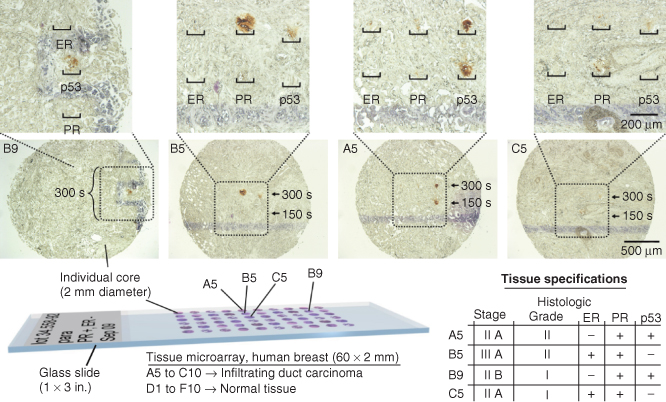
Figure 6.6 µIHC processing of selected cores of an infiltrating ductal carcinoma breast tissue microarray, each 2 mm in diameter. Each core of the tissue array is characterized a priori by the supplier for the expression of ER, PR, and p53. Four cores of the tissue microarray (locations A5, B5, B9, and C5) were processed with the vMFP (α-ER: 370 µg/mL, α-PR: 125 µg/mL, and α-p53: 54 µg/mL).
6.5 Millimeter-Scale Immunohistochemistry
We leveraged the inherent capabilities of MFP-based µIHC such as reduced incubation time, reduced primary antibody consumption, and the multiplexing capability of µIHC to the mm scale. Using slit-aperture and aperture-array probe heads, we demonstrated the staining of individual cores of a TMA to enable multiplexed analysis. Individual cores could be treated with different primary antibodies, or a single core could be exposed to distinct primary antibodies. Importantly, with these new families of probes, it is feasible to stain a core of interest or perform in-depth analysis of a selected core. For uniform millimeter-scale processing of a single core, we used a design with an injection aperture of 1 mm × 0.05 mm and an aspiration aperture of 4 mm × 0.05 mm (Figure 6.7a, inset). This results in an HFC with a width of 1.2 mm, staining an area of about 2.4 mm2 when scanned across a tissue core with a diameter of 2 mm. The unprocessed area on this core could be used, for example, to perform analysis with an additional antibody [25]. We performed IHC on a breast cancer TMA slide. Here, the primary antibody (Ab) (α-p53, at a concentration of 25 µg/mL) was delivered with the MFP. We added rhodamine B at a concentration of 10 µM to visualize the HFC. Rhodamine B binds non-covalently to the tissue and is washed by the flow of immersion liquid during scanning of the probe over the tissue (Figure 6.7a). The HFC extends about 330 µm in the Y-direction; thus the chosen local incubation time of the primary Ab with the tissue section at the scanning speed of 0.01 mm/s was about 33 s. All the other steps of IHC were performed for the entire TMA slide. In contrast to conventional methods, where the primary Ab incubation is in the order of hours, here the incubation was performed within seconds. This is due to the convective transport of the molecules to the substrate, resulting in an enhancement of reaction kinetics, and also to the application of higher concentrations of primary Abs. Using the set of parameters given above, we incubated a 2 mm TMA core with primary Abs in 2.5 min, consuming approximately 7.5 µL of processing liquid.
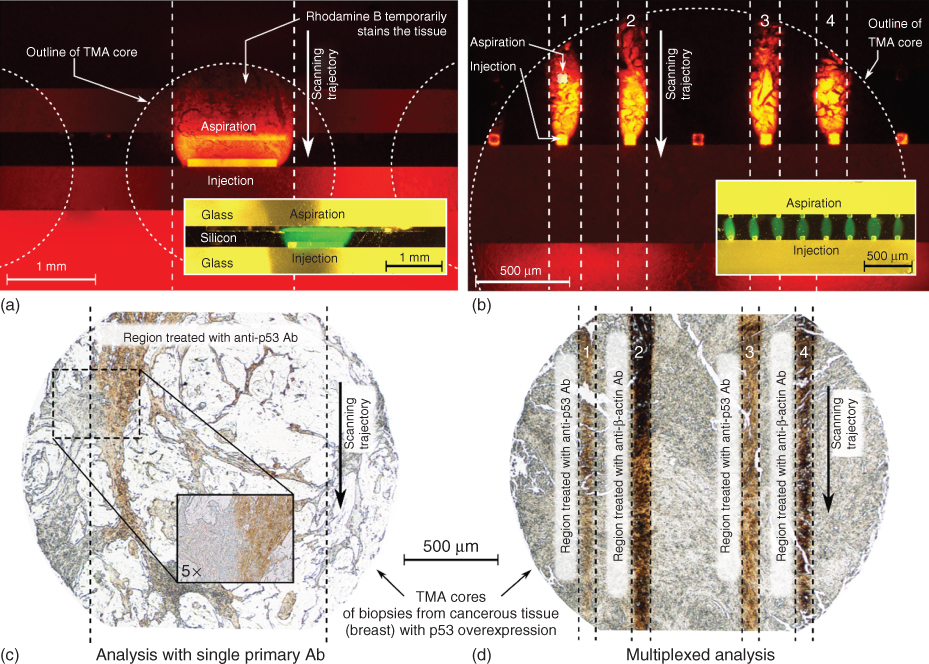
Figure 6.7 Processing of tissue sections in a tissue microarray (TMA) on the millimeter scale using HFC. (a) Uniform staining of a tissue section overexpressing p53. A slit-aperture probe is used to apply a processing liquid containing α-p53 Abs and rhodamine B. Inset: Bright-field image of a slit-aperture probe creating a 1 mm × 0.3 mm HFC of a processing liquid that contains fluorescein. (b) Multiplexed staining of a tissue section overexpressing p53. An aperture-array probe is used to apply processing liquids that contain α-p53 Abs or α-β-actin Abs and rhodamine B. Inset: Bright-field image of an aperture-array probe creating eight parallel HFCs of processing liquids containing fluorescein. (c) Bright-field image of a tissue section after treatment with α-p53 Abs using a slit-aperture probe and chromogenic visualization. Inset: 5× magnification of the edge of the treated region. (d) Bright-field image of a tissue section after treatment with α-p53 Abs and α-β-actin Abs by means of an aperture-array probe and chromogenic visualization.
The concentration of primary Abs used in conventional IHC (on the order of 1 µg/mL) is typically significantly lower compared with the concentrations used in the discussed experiments. We did not focus on minimizing the Ab consumption. However, consumption can be reduced by optimizing the flow rates, incubation times, and the Ab concentration. The total time required for processing an entire TMA can be further optimized by using multiple probes or stacked probes or by creating HFCs with a larger contact area with the substrate.
We also performed multiplexed staining by confining two primary Ab solutions (α-p53 and α-β-actin, both at 25 µg/mL) in four parallel, independent HFCs using an aperture-array probe capable of creating eight HFCs (Figure 6.7b, inset). The remaining four HFCs were run with PBS as the processing liquid (processing liquids in the eight adjacent HFCs: PBS – PBS – (α-p53) – (α-β-actin) – PBS – (α-p53) – (α-β-actin) – PBS). The injection flow rate for each HFC was 0.5 µL/min and Qi/Qa = 1/4. The area processed with each of the two Ab solutions was about 0.5 mm2, which sufficiently provides a measure of the antigen expression within the sample (Figure 6.7c,d).
6.6 Outlook
The devices and methods presented in this chapter enable versatile and localized interaction of different processing liquids with immersed, centimeter-scale substrates. Surface (bio)chemical assays in general would benefit from the ability to sequentially and simultaneously apply different liquids onto a surface. These multiplexing techniques, in combination with the scanning capability of the probe, enable versatile spatiotemporal alterations of selected regions of a substrate. Slit-aperture probes and also aperture-array probes enable the creation of localized gradients on a surface. Using a slit-aperture design, gradients can be created by supplying different liquids to the injection aperture through independent channels. Probes with aperture-array designs allow the creation of discrete gradients by confining different proportions of two liquids in adjacent HFCs. The width of single HFCs and also the spacing between neighboring HFCs in such an array could be scaled down significantly [16] to provide a higher resolution for creating such gradients. To enable conformal processing of a substrate with parallel HFCs, aperture-array probes could also be scanned over a substrate at an inclined angle (rotation around Z-axis) to enable an overlap between the areas processed with separate HFCs.
We further believe that using the methods presented in this chapter, in combination with sequencing different liquids within each injection line, would be helpful for implementing a range of (bio)chemical assays on a surface. This could be done by the controlled insertion and removal of immiscible spacers, thereby minimizing Taylor dispersion [26]. Moreover, we believe it is conceivable to integrate the methods presented with techniques to perform local temperature alterations [25] to assist in performing efficient chemical reactions.
In a research setting, the key use of millimeter-scale liquid interactions with a substrate lies in enabling multiplexing in all the steps of an analysis. In a clinical environment, the short incubation times enabled by HFC of the processing liquids might allow the deployment of, for example, IHC analysis to be done during surgery, while the ability to acquire more detailed information on selected areas of interest can potentially enable a more targeted and more efficient analysis of tissue sections.
As local areas are biochemically processed and adjacent regions are left intact, the contrast for visualization is improved, facilitating histological statements. In summary, HFC-assisted immunohistochemistry from micrometer to millimeter scale can not only support the work of pathologists but may also become a tool of choice for research and diagnostics involving biological substrates.
Acknowledgments
This work was in part supported by the European Research Council (ERC) Starting Grant, under the 7th Framework Program (Project No. 311122, BioProbe). The authors thank Aditya Kashyap, Anna Fomitcheva Khartchenko, Marios Georgiadis and Ismaël Marc Zeâf for help during experiments, and Ute Drechsler for help with fabricating probe heads.
References
- 1 Dabbs, D.J. (2013) Diagnostic Immunohistochemistry, 4th edn, Elsevier Health Sciences.
- 2 Xing, Y., Chaudry, Q., Shen, C., Kong, K.Y., Zhau, H.E., Chung, L.W., Petros, J.A., O'Regan, R.M., Yezhelyev, M.V., Simons, J.W. et al. (2007) Bioconjugated quantum dots for multiplexed and quantitative immunohistochemistry. Nat. Protoc., 2 (5), 1152.
- 3 Gannot, G., Tangrea, M.A., Gillespie, J.W., Erickson, H.S., Wallis, B.S., Leakan, R.A., Knezevic, V., Hartmann, D.P., Chuaqui, R.F., Emmert-Buck, M.R. et al. (1998) Layered peptide arrays. J. Mol. Diagn., 7 (4), 427–436.
- 4 Sun, J., Masterman-Smith, M.D., Graham, N.A., Jiao, J., Mottahedeh, J., Laks, D.R., Ohashi, M., DeJesus, J., Kamei, K., Lee, K.-B. et al. (2010) A microfluidic platform for systems pathology: multiparameter single-cell signaling measurements of clinical brain tumor specimens. Cancer Res., 70 (15), 6128–6138.
- 5 Kim, M.S., Kim, T., Kong, S.-Y., Kwon, S., Bae, C.Y., Choi, J., Kim, C.H., Lee, E.S., and Park, J.-K. (2010) Breast cancer diagnosis using a microfluidic multiplexed immunohistochemistry platform. PLoS One, 5 (5), e10441.
- 6 Blake, A.J., Pearce, T.M., Rao, N.S., Johnson, S.M., and Williams, J.C. (2007) Multilayer PDMS microfluidic chamber for controlling brain slice microenvironment. Lab Chip, 7 (7), 842–849.
- 7 Ciftlik, A.T., Song, B., Vandevyver, C., Buenzil, J.-C.G., Lehr, H.-A., and Gijs, M.A.M. (2010) Fast immunohistochemical biomarker detection device for cancer tissue slices. Proceeding of 14th International conference on Miniaturized Systems for Chemistry and the Life Sciences, p. 669.
- 8 Song, B., Sivagnanam, V., Vandevyver, C.D.B., Hemmilä, I., Lehr, H.-A., Gijs, M.A.M., and Bünzli, J.-C.G. (2009) Time-resolved lanthanide luminescence for lab-on-a-chip detection of biomarkers on cancerous tissues. Analyst, 134 (10), 1991–1993.
- 9 Meister, A.A., Gabi, M., Behr, P., Studer, P., Vörös, J., Niedermann, P., Bitterli, J., Polesel-Maris, J.J., Liley, M., Heinzelmann, H. et al. (2009) FluidFM: combining atomic force microscopy and nanofluidics in a universal liquid delivery system for single cell applications and beyond. Nano Lett., 9 (6), 2501–2507.
- 10 Momotenko, D., Cortes-Salazar, F., Lesch, A., Wittstock, G., and Girault, H.H. (2011) Microfluidic push–pull probe for scanning electrochemical microscopy. Anal. Chem., 83, 5275–5282.
- 11 Bruckbauer, A., Ying, L., Rothery, A.M., Zhou, D., Shevchuk, A.I., Abell, C., Korchev, Y.E., and Klenerman, D. (2002) Writing with DNA and protein using a nanopipet for controlled delivery. J. Am. Chem. Soc., 124 (30), 8810–8811.
- 12 Chen, D., Du, W., Liu, Y., Liu, W., Kuznetsov, A., Mendez, F.E., Philipson, L.H., and Ismagilov, R.F. (2008) The chemistrode: a droplet-based microfluidic device for stimulation and recording with high temporal, spatial, and chemical resolution. Proc. Natl. Acad. Sci. U.S.A., 105 (44), 16843–16848.
- 13 Tavana, H., Jovic, A., Mosadegh, B., Lee, Q.Y., Liu, X., Luker, K.E., Luker, G.D., Weiss, S.J., and Takayama, S. (2009) Nanolitre liquid patterning in aqueous environments for spatially defined reagent delivery to mammalian cells. Nat. Mater., 8 (9), 736–741.
- 14 Juncker, D., Schmid, H., and Delamarche, E. (2005) Multipurpose microfluidic probe. Nat. Mater., 4 (8), 622–628.
- 15 Ainla, A., Jeffries, G.D.M., Brune, R., Orwar, O., and Jesorka, A. (2012) A multifunctional pipette. Lab Chip, 12 (7), 1255.
- 16 Kaigala, G.V., Lovchik, R.D., Drechsler, U., and Delamarche, E. (2011) A vertical microfluidic probe. Langmuir, 27 (9), 5686–5693.
- 17 Lovchik, R.D., Kaigala, G.V., Georgiadis, M., and Delamarche, E. (2012) Micro-immunohistochemistry using a microfluidic probe. Lab Chip, 12 (6), 1040.
- 18 Autebert, J., Cors, J.F., Taylor, D.P., and Kaigala, G.V. (2016) Convection-enhanced biopatterning with recirculation of hydrodynamically confined nanoliter volumes of reagents. Anal. Chem., 88 (6), 3235–3242.
- 19 Ainla, A., Jansson, E.T., Stepanyants, N., Orwar, O., and Jesorka, A. (2010) A microfluidic pipette for single-cell pharmacology. Anal. Chem., 82 (11), 4529–4536.
- 20 Queval, A., Ghattamaneni, N.R., Perrault, C.M., Gill, R., Mirzaei, M., McKinney, R.A., Juncker, D., Gähwiler, B.H., Capogna, M., Debanne, D. et al. (2010) Chamber and microfluidic probe for microperfusion of organotypic brain slices. Lab Chip, 10 (3), 326–334.
- 21 Shiku, H., Yamakawa, T., Nashimoto, Y., Takahashi, Y., Torisawa, Y., Yasukawa, T., Ito-Sasaki, T., Yokoo, M., Abe, H., Kambara, H. et al. (2009) A microfluidic dual capillary probe to collect messenger RNA from adherent cells and spheroids. Anal. Biochem., 385 (1), 138–142.
- 22 Emmert-Buck, M.R., Bonner, R.F., Smith, P.D., and Chuaqui, R.F. (1996) Laser capture microdissection. Science, 274, 998–1001.
- 23 Sauter, G., Simon, R., and Hillan, K. (2003) Tissue microarrays in drug discovery. Nat. Rev. Drug Discovery, 2 (12), 962. doi: 10.1038/nrd1254
- 24 Camp, R.L., Charette, L.A., and Rimm, D.L. (2000) Validation of tissue microarray technology in breast carcinoma. Lab. Invest., 80 (12), 1943. doi: 10.1038/labinvest.3780204
- 25 Cors, J.F., Stucki, A., and Kaigala, G.V. (2016) Hydrodynamic thermal confinement: generation of thermo-chemical microenvironments on biological substrates. Chem. Commun., 52, 13035–13038.
- 26 Van Kooten, X.F., Autebert, J., and Kaigala, G.V. (2015) Passive removal of immiscible spacers from segmented flows in a microfluidic probe. Appl. Phys. Lett., 106 (7), 074102.