
Chapter 1
Hydrodynamic Flow Confinement Using a Microfluidic Probe
Emmanuel Delamarche, Robert D. Lovchik, Julien F. Cors and Govind V. Kaigala
IBM Research – Zurich, Säumerstrasse 4, 8803 Rüschlikon, Switzerland
1.1 Introduction
Photolithography, the art of patterning surfaces using light projected through an optical mask and chemicals sensitive to light, reached an extraordinary level of sophistication for producing microelectronic components reaching sub-20 nm dimensions on a massive manufacturing scale with extremely high yields. While photolithography had started in the 1960s for fabricating integrated circuits, it essentially remained confined to the structuring and modification of inorganic surfaces and materials. Strong progress on sequencing genomes, an increased understanding of the complexity of cells, tumors, tissues and organs, and emerging work on cell–environment interactions called for new techniques that could tailor biological interfaces and analyze challenging biological specimens. It took, for example, until the 1990s before peptides and oligonucleotides were patterned on glass slides using combinatorial masks and photolithography [1, 2], DNA [3] and protein [4] microarrays were demonstrated, self-assembled monolayers were patterned using soft lithography [5], and various “inks” were deposited on surfaces with nanometer precision using scanning probe methods [6]. All together these techniques are impressive because they can deal with many types of inks, are precise, can cover very large areas, and can be fast and inexpensive. There is, however, a general need for controlling the chemical environment during the deposition of species onto surfaces, the analysis of surfaces, and the study of (bio)interfaces. Controlling the chemical environment here means being able to work with various solutions (biological buffers, culture medium, solvents, etc.) without drying artifacts, potentially at a specific temperature, and being able to change this chemical environment in a flexible manner. The control over the chemical environment on a surface can be achieved, for example, by (i) isolating areas of a surface using microfluidic channels and laminar streams of solutions [7, 8], (ii) applying locally chemicals using a probe [9], or (iii) compartmentalizing chemicals near a surface using nonmiscible liquids [10, 11]. The ability to control a chemical environment on a surface is probably most interesting for biological applications for several reasons: First, investigating the structure and function of proteins, cells, and tissues on surfaces is fundamental. Second, biomolecules and cells are fragile and require appropriate liquid environments such as biological buffers and culture media. Third, cells and tissues are complex heterogeneous systems, and there is a benefit in probing individual cells and particular areas of tissue sections to deal with the complexity of such samples and to use adjacent areas for comparison [12].
Microfluidics represent a powerful approach for interacting with surfaces and studying biological interfaces because the flow of liquids at the microscale is usually laminar and therefore predictable and well defined [13, 14], microfluidic devices can localize chemical processes and environments on surfaces with micrometer precision [15], and microfluidics are conservative of reagents and samples. However, most of microfluidics are closed systems and need either to be sealed on surfaces/samples or samples must be introduced inside microfluidic structures [16, 17]. These challenges can be circumvented by having a device operating in an open space and nearby a surface [18]. Several concepts of “open space” microfluidics have been developed (Figure 1.1). In the example of the FluidFM technology [19], microfluidic channels are integrated to a cantilever for atomic force microscopy, and liquids can be injected or aspirated while scanning a surface. Scanning ion conductance microscopy has also been used to release chemicals using electrophoresis, electroosmosis, and dielectrophoresis from nanopipettes to cells with sub-micrometer precision [20]. These two examples harbor high precision both for scanning and delivery of chemicals but are very dependent on the proximity between the delivering probe and the surface. This requirement can be relaxed by using an aqueous two-phase system. In this case, one phase, which contains the chemicals of interest, can be inserted through the second phase for patterning or interacting with a surface [21]. Finally, a liquid can be localized on a surface using lateral hydrodynamic boundaries formed by a second miscible liquid. This concept is termed hydrodynamic flow confinement (HFC) and can be implemented using the microfluidic probe (MFP) technology [22]. All together, the methods illustrated in Figure 1.1 are powerful for interacting with living cells and tissues and for patterning surfaces with high flexibility on length scales ranging from micrometers to centimeters [18].
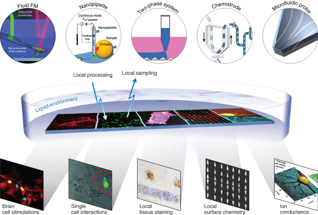
Figure 1.1 Local interaction between liquids containing chemicals, biomolecules, and/or cells with a variety of surfaces can be done using scanning noncontact probes. Some of these probes deliver liquids or charged molecules in close proximity to the surface, use nonmiscible liquids to apply a liquid of interest locally to the surface, or use HFC of a liquid inside another one using a multi-aperture microfabricated probe.
This chapter describes the MFP technology in general terms and explains how to design and fabricate MFP heads for implementing HFC of a liquid on a surface. Theoretical descriptions of HFC, applications of the MFP technology, and advanced implementations of HFC as well as alternative approaches for local processing of surfaces are also presented in the following chapters.
1.2 HFC Principle
HFC of a liquid on a surface can be achieved by bringing an MFP head having a face comprising two coplanar microapertures at a distance d above a substrate (Figure 1.2a,b). This distance typically ranges from a few micrometers up to 100 µm, and the resulting gap between the MFP head and the surface is filled with a liquid [22]. This liquid is called the immersion liquid and is typically water, a biological buffer, or a culture medium, depending on the substrate and if proteins or cells are present on the substrate. By injecting and re-aspirating a processing liquid in the gap filled with the immersion liquid through the apertures, the processing liquid flows from one aperture to the other in a laminar regime. This flow is guided by the solid boundaries provided by the substrate and the apex of the MFP head and is directed toward the aspiration aperture together with some of the immersion liquid (Figure 1.2c,d). The immersion liquid is critical for laterally confining the processing liquid in the region beneath the apertures. In addition, HFC can be lost if the ratio of aspiration/injection flow rates (Qa/Qi) reaches a low value. This value essentially depends on d and the distance separating the apertures. As a rule of thumb, Qa should be at least three times Qi [18, 19]. More details on modeling HFC [23, 24] and implementing HFC using more than two apertures [25, 26] are provided in Chapters 2–5.
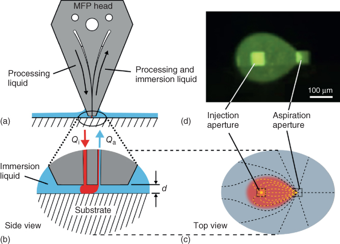
Figure 1.2 Principle of HFC of a liquid on a substrate using an MFP. (a) A microfabricated head having at least two microapertures is brought close to a surface. (b) When the apex of the MFP head is immersed in an immersion liquid covering a substrate of interest, a processing liquid can be injected and confined on the surface by re-aspirating it together with some of the immersion liquid. (c) The dimensions and spacing of the apertures influence the footprint of the injection liquid on the surface as depicted on this top view. (d) Working on a transparent substrate/sample and having a fluorescent dye in the injection liquid permits direct visualization of the confined liquid using an inverted fluorescence microscope.
The excursion of the processing liquid in space and the consecutive footprint of the processing liquid on a substrate depend on fixed and variable parameters. Fixed parameters are the geometry, lateral dimensions, and spacing of the apertures. Variable parameters are Qi, Qa, d, and the displacement velocities of the MFP head over the substrate (see the following text).
1.3 MFP Heads
The first implementation of HFC using an MFP relied on hybrid heads made from a patterned Si chip bonded to a polydimethylsiloxane (PDMS) layer (Figure 1.3a,b) [22]. Square apertures with lateral dimensions as small as 10 µm were fabricated at the surface of a double-side polished Si wafer using deep reactive ion etching (DRIE). The other side of the wafer was etched to form microchannels and circular cavities. Through-wafer etching then created vias connecting the microchannels to the apertures. A PDMS block comprising through holes was bonded to the Si chip after O2 plasma activation, and glass capillaries were inserted into the holes in the PDMS to provide fluidic connection between computer-controlled syringe pumps and the circular cavities on the Si chip. Structural stability and adhesion between the PDMS and the Si chip were sometimes a problem, limiting the yield of fabrication of such MFP heads. This was solved by making multilayer MFP heads [27]: the lower side of a double-side polished Si wafer comprised microapertures, and the upper side of the wafer was structured with macroscopic channels. A second Si wafer comprised cavities for bonding microfluidic ports (Figure 1.3c). Both Si wafers were bonded using a spin-coated polyimide adhesion layer and by applying a 2 bar pressure for 10 min at 320 °C. Dicing the bonded wafers yielded individual MFP heads, which were convenient to connect to pumps using NanoPort™ assemblies (Figure 1.3d). Such heads can be used with a large variety of solvents and flow rates and are very robust compared with Si/PDMS heads, but their relatively large footprint requires careful alignment for parallelism when they are positioned over a substrate to ensure constant separation distance between the head and the substrate and to avoid contact between the edges of the head and the substrate.
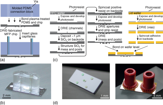
Figure 1.3 MFP heads fabrication. (a) Initial heads had microapertures defined on one face of a Si wafer, through-wafer vias made using DRIE, and the top face bonded to a PDMS connection block inside which glass capillaries (not shown in the image) were inserted (b). Subsequent multilayered heads (c) had increased structural stability by using a thin Si wafer for defining the apertures and another Si wafer for creating access ports and an interface for bonding microfluidic ports. (d) Photographs showing (left) the scanning face of the head with the mesa and microapertures at the center and (right) the top face with ports.

Figure 1.4 Design and fabrication of vMFP heads. (a,b) These heads result from etching microchannels in the main plane of a Si wafer, sealing the microchannels by bonding a glass wafer to the Si wafer, and dicing the bonded layers to create apertures at the apex of the head. The silicon wafer has vias etched in the area where microfluidic ports are applied for connecting the head to high-precision pumps. (c) Anodic bonding of the glass ensures strong and tight sealing, and (d) designing heads with diamond shapes eases dicing and allows dense packing of heads on a wafer. (e,f) After dicing, polishing the apex of heads is required for yielding well-defined heads. The optical micrographs show four heads stacked together before and after polishing.
1.4 Vertical MFP
In the previous examples of MFP heads, through-wafer etching had to be performed to ensure the connection of apertures with larger channel structures located on the other face of the head onto which fluidic ports could be established. Through-wafer etching using DRIE is a time-consuming process that can have limited resolution. An alternative is to create microchannels and structures for fluidic connection on the same face of the MFP head (Figure 1.4a). A set of converging microchannels with a width or depth of just a few micrometers can easily be patterned in Si wafers using standard lithography and etching (Figure 1.4b). Anodic bonding of a glass wafer seals the microchannels (Figure 1.4c), and single heads and apertures are created by simply dicing the bonded wafers (Figure 1.4d). The dicing process needs to be followed by a polishing step to ensure well-defined apertures. Vias are drilled/etched in the silicon layer onto which fluidic ports can be bonded. We call this implementation of heads and MFP technology “vertical” microfluidic probe (vMFP) [28]. This implementation is particularly favorable in terms of fabrication yield, number of heads that can be made per wafer, keeping the apex of the MFP very small (e.g., 1 × 1 mm2), viewing filling of liquids in the head through the transparent glass layer, and spreading vias and fluidic connections over the face of the head. Microchannels can also be patterned so as to have varying width, orientation, or separation distance along their main axis. Therefore, a particular aperture width or separation distance between the apertures can be obtained based on where dicing along the microchannels is done. The arrangement of MFP heads on a wafer is convenient for producing multiple heads in parallel, but this necessitates steps for separating individual heads. Heads can be separated by dicing, which is a standard technique in microfabrication and packaging. Dicing creates rough edges, however, and the apex of heads where apertures are located must be polished (Figure 1.4e,f). A comparison of the methods for fabricating planar, vertical, and PDMS-based MFP heads is provided in a detailed review [29].
1.5 Advanced MFP Heads and Holders
The world-to-chip interface challenge is an ubiquitous issue with microfluidics. This challenge refers to the problem of connecting micrometer-sized channels to more macroscopic elements such as fittings, tubings, needles, and pipettes in a reliable, leak-free manner and with dead volumes as small as possible [30]. MFP heads are no exception to this challenge. One strategy is to mechanically clamp the head using two parts of a holder (Figure 1.5a–c): the back of the head can be mounted on a holder having mechanical alignment features and a rod for mounting on an MFP platform [28]. The front of the head having vias for fluidic connections can then be sealed using gaskets and a holder carrying tubings. The need for a larger number of fluidic connections can be satisfied by arraying vias around a central hole used for mounting the head on a holder. The vMFP head shown in Figure 1.5d has one mounting and two alignment holes and six vias for fluidic connection. The vias, which are patterned in the Si layer of the head, are regularly distributed around the central hole to accommodate a circular connector for up to eight capillaries. Increasing the number of capillaries, channels, and apertures on a head opens up numerous possibilities. For example, an immersion liquid can be dispensed by one or several apertures located near the periphery of the head apex. This can ensure the continuous presence of an immersion liquid in the gap between the substrate and the head for long experiments (>1 h) or patterning operations. It also lowers the risk of contamination through dust particles from outside. Alternatively, the composition of the immersion liquid might be changed over time in a programmable way. The minimum number of apertures for HFC is 2, and with more apertures, various liquids can be confined in parallel or nested within each other (see Chapter 2).
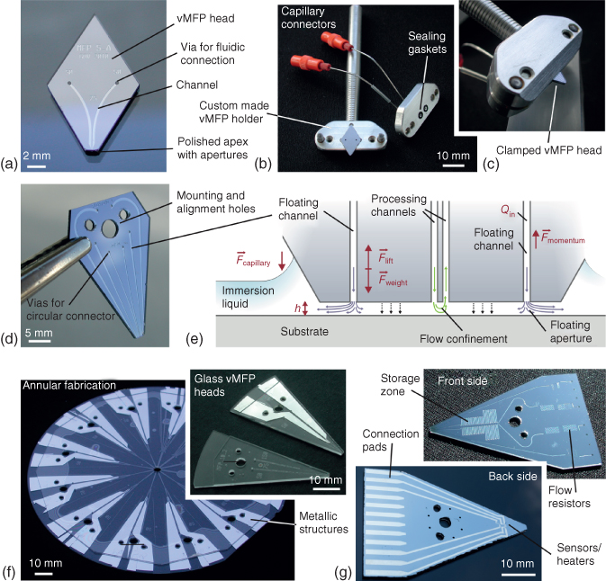
Figure 1.5 Example of vMFP heads for various HFC implementations. (a) Photograph of a vMFP having two apertures and vias for fluidic connection with (b,c) the head mounted on a custom-made holder and clamped with a sealing gasket. (d) Photograph of a vMFP head comprising six microchannels and apertures, two of which being used for injecting an immersion liquid toward the substrate and lifting the head by means of hydraulic pressure (e). (f) Photograph of two bonded glass wafers with annular vMFP heads. The apexes of all heads are formed at once by drilling a hole in the center of the wafer and polishing the edges of the formed ring; dicing the wafer yields heads ready for use (inset). (g) The Si face of a head that is bonded to the glass layer can carry channels having significant volume (>1 µL) and the back of the Si can be patterned with metals to provide, for example, microheaters and temperature sensors.
Alternatively, a same processing liquid can be applied using a pair of injection apertures so as to create a force in the gap between the head and the substrate for lifting the head (Figure 1.5e). This is an implementation, which was demonstrated using the rocking arm of an LP phonograph and termed “floating MFP” [31]. A vMFP head was mounted at the end of the arm, while the weight on the other end of the arm was adjusted to nearly balance the weight of the head and tubings. A self-adjusting distance between the head and the substrate was achieved by adjusting the flow rate of immersion liquid injected into the gap. The key idea behind this concept was to be able to scan curved or uneven surfaces. An additional positive aspect of this approach was that distance control could be easily achieved on opaque substrates without means of active control systems. Most reported MFP implementations require, at least at the beginning of the experiments, a transparent area on the substrate for zeroing the MFP head position relative to the surface of the substrate. This is generally done by approaching the surface with the head and setting the position to zero as soon as optical fringes appear.
The face of the MFP head over the substrate needs to be planar for providing a constant gap and steady HFC. This can be important for patterning surfaces with resolution in the micrometer range. Polishing this face of the head is critical for this reason. Polishing can be cumbersome and labor intensive because the rate of polishing needs to be calibrated and only a few heads can be polished at once. An alternative is to array heads on a wafer in a centrosymmetric manner with the apex of each head close to the center (Figure 1.5f). In the example provided in this figure, heads were made of two glass wafers, which were thermally bonded. Drilling a hole at the very center and polishing the edges of the resulting apex of heads allow for the creation and polishing of apertures on all heads in a single step. Such annular heads have a slightly curved apex, which is not an issue for the gaps typically used (a few tens of micrometers) during processing of a substrate. The curvature of the apex can be adjusted through the selection of the diameter of the center drilled hole and is reduced when the drilled hole has a larger diameter. Both wafers can be drilled for creating mounting/alignment vias, or the glass wafer only can be drilled to open microfluidic vias. The Si wafer can be coated with a thermally grown oxide and patterned with metal patterns used as electrodes or heating elements. There is in principle no limit to the size of MFP heads and the fabrication cost of a head scales with the area of the head. A 4″ Si wafer can have 30 or more vMFP heads [28]. Heads with eight microchannels and apertures, 12 metallic connection pads, and serpentine microchannels that can store up to 1 µL of liquid can reach a size of up to 5 cm × 3 cm (Figure 1.5g). Heads can also comprise reservoirs containing liquids of interest. This was, for example, demonstrated on a multifunctional pipette by fabricating microchannels and reservoirs in a PDMS layer sandwiched in between a glass substrate and a manifold cover. Pressurization of a particular reservoir was used for injecting or aspirating liquid at the apex of the pipette [32].
1.6 Surface Processing Using an MFP
Surface treatments are either subtractive or additive depending on whether they remove parts of the surface or add components to it. Subtractive processes are used for engraving surfaces directly, using, for example, wet or dry etching processes, plasma-based processes, laser ablation, or micro-milling. Additive processes may be based on vapor phase or plasma-induced deposition, evaporation, and sputtering of materials used in combination with a mask or stencil, electrochemical, or electroless deposition of metals from bathes [33]. In general, processes that require significant removal or addition of chemicals to large areas of a surface might be an issue for implementation using an MFP: HFC localizes liquids typically on small areas of a surface. Therefore, the deposition or removal of materials of significant depth/thickness and large areas may require long residence times of the head at particular locations and an overall large time budget. Many research areas and applications however require only minute modification of surfaces. The wetting characteristics of surfaces can, for example, be controlled using monolayers only 1 or 2 nm thick [34]. Activation of surfaces for cross-linking proteins or promoting adhesion can be achieved by functionalizing surfaces with epoxy groups, aldehydes, esters, vinyl groups, carboxylic acids, activated esters, maleimides, and thiols, for example [35]. The patterning of cells to surfaces can alike be done by coating surfaces locally with cell adhesion proteins or peptides [36]. Electroless deposition of metals only needs activation of a surface with catalysts [37]. In these examples, an MFP should be able to provide the chemicals required for surface processing, and limitations are likely to originate from material incompatibilities between the processing liquid and the MFP head or immiscibility between the processing and immersion liquids.
Taking the example of depositing antibodies on surfaces, we can examine the role of the flow rates and distance between the head and the surface on the resulting antibody patterns (Figure 1.6). In this figure, antibodies are labeled with a fluorophore and can be visualized once deposited on the glass surface by means of fluorescence microscopy [28]. For gaps smaller than ∼10 µm, the footprint of the processing solution over the surfaces sharply increases as the gap is reduced and for a given injection and aspiration flow rate. At small gaps, the flow path from one aperture to the other leads to an extension of the processing liquid further away from the injection aperture before it flows back to the aspiration aperture. For larger gaps, this extension of the processing liquid over the surface is less pronounced and starts to scale more linearly with the ratio between injection and aspiration flow rates. In other words, at constant gap, increasing the injection flow rate forces the processing liquid to explore more the gap between the head and the surface. If the gap is further increased, above ∼ 50 µm in the example provided by Figure 1.6, the bottom envelope of the processing liquid does not contact the underlying surface anymore. Modeling and analytical descriptions of HFC are detailed in Chapters 2–4. In addition, Chapters 2 and 6 provide detailed accounts of patterning proteins and localizing assays on surfaces using HFC and an MFP. The findings in Figure 1.6 suggest that patterning surfaces can easily be done with gaps between 10 and 50 µm for these specific designs of heads. For gaps in this range, the topography of surfaces should not influence significantly HFC, and resulting patterns would essentially not be affected by the presence of cells, proteins, and thin polymeric layers, for example.
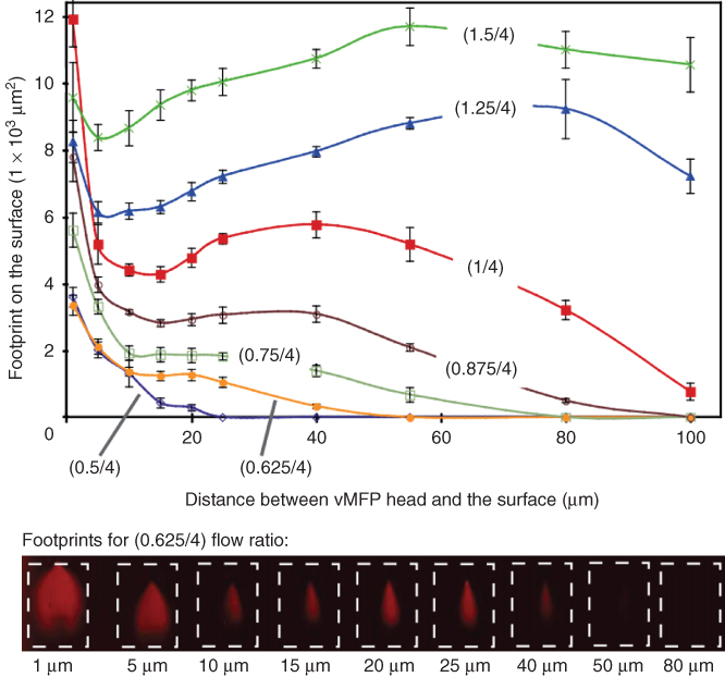
Figure 1.6 Evolution of the footprint of a solution containing fluorescently labeled antibodies on an activated glass surface for various flow conditions and distances between a vMFP head and the glass surface. The footprint is assessed by visualizing the pattern of antibodies deposited on the glass using fluorescence microscopy. The injection and aspiration flow rates were gradually varied from 0.4/4 (injection/aspiration) to 1.25/4 µL/s for gaps between 1 and 80 µm. The head used for these experiments had two square apertures with a lateral dimension of 50 µm and a separation distance between the apertures of 50 µm. The dotted rectangles in the images serve as visual guides and have an area of ∼1.4 × 104 µm2.
HFC can be used beyond “just” patterning proteins and in a way that can be very challenging for conventional patterning techniques. The ability to scan a surface and position a processing liquid along lines and continuous patterns on a surface can be fundamentally changed by significantly increasing the lateral displacement velocity of the MFP head over the surface [22]. In Figure 1.7a, discontinuous patterns of fluorescently labeled antibodies on an aldehyde-functionalized glass were formed by alternatively moving the head in one direction at a velocity of 500 µm/s (“non-writing mode”) and leaving the head stationary for 2 s (“writing mode”). At high lateral velocities, the processing liquid cannot displace the immersion liquid in contact with the surface, and direct interaction between the processing liquid and the surface is lost. The writing and non-writing modes can be conveniently combined for writing discontinuous patterns on a surface without having to stop/resume the injection of processing liquid or move up and down the MFP head over the surface. In these examples, the consumption of protein solution per “spot” area can be very small, in the order of a few picoliters per spot [22], but writing large patterns and having a continuous flow of processing solution may still result in using microliters of protein solution for patterning areas of 1 cm2 or larger. Dead volumes originating from tubing, fittings, and microchannels connecting the apertures to syringes can also be large and cumbersome if a processing liquid needs to be frequently changed.
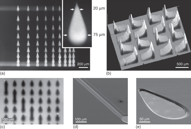
Figure 1.7 Examples of surface patterning using an MFP. Fluorescence microscope images showing discontinuous patterns of fluorescently labeled proteins patterned (a) on an aldehyde-activated glass and (b) on a glass slide using variable scanning velocity for producing surface gradients of proteins and (c) obtained by local removal of the proteins from a homogeneous monolayer. (d,e) Optical microscope images showing patterns in a 3 µm thick photoresist obtained by local development of the photoresist using an MFP.
The velocity of lateral displacement of the head across the surface can be varied in a continuous manner as well. This is useful for forming surface chemical gradients or exploring processing conditions (e.g., effect of residence time). Creating chemical gradients on surfaces [38–40] or implementing “grayscale” lithography is challenging using conventional methods [41, 42]. Microfluidic-based approaches, with or without simultaneous use of light and light-sensitive materials, may provide simple solutions to the 3D structuring of surfaces or formation of chemical gradients on surfaces [41]. In fact, forming gradients and even protein gradients using an MFP is a particularly simple process (Figure 1.7b) [22]. The previous examples concern additive processes, but the processing liquid can also be used for subtractive processes such as removing proteins from a surface using, for example, alkaline solutions and surfactants (Figure 1.7c) [22], locally dissolving photoresist using a developer (Figure 1.7d,e) [27], removing lipid bilayers from a surface [43], and removing/lysing cells (e.g., using a trypsinization process, bleach, or a digestion cocktail) [18, 21].
Irrespectively of whether HFC is used for additive or subtractive processes, HFC is a very versatile approach for processing heterogeneous and fragile surfaces; local processing also makes unnecessary the need for protection of sensitive materials and areas of a substrate.
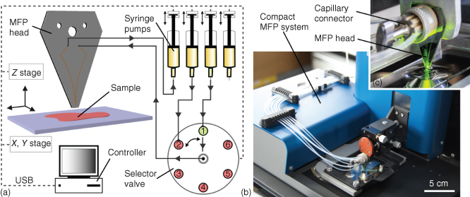
Figure 1.8 Microfluidic probe components and implementation. (a) An MFP head is connected to a selector valve and pumps for scanning a surface of interest. Typically, all peripherals are computer controlled. (b) Photograph of a cMFP placed on the stage of an inverted fluorescence microscope. The two blue units hold the X-, Y-, and Z-axis stages and goniometers for adjusting the MFP head parallel to the substrate and the scanning plane. Six tubings connect the head to pumps and waste reservoirs via a capillary connector as shown in (c).
1.7 MFP Components
Realizing HFC of liquids on surfaces requires setting up an MFP platform using components having appropriate characteristics (Figure 1.8a) [44]. Usually, an inverted microscope is used so that HFC and particular areas of a sample can be imaged and monitored. Many biological samples such as thin tissue sections, layers/patterns of proteins on glass slides and Petri dishes, and adherent cells on culture dishes are transparent. This means that HFC and the sample can be monitored by viewing through the sample using standard inverted microscopes and objectives and in optical or fluorescence modes. Scanning a sample and setting a gap between the MFP head and the substrate obviously require a positioning system. Ideally, this system should have a positioning accuracy in the micrometer range along the X, Y, and Z directions. The in-plane scanning range should at least be equivalent to half the surface area of a glass slide (i.e., ∼37 × 25 cm2) so that samples located near the center of a glass slide can be used. It also might be useful to have much larger scanning areas for working with two microtiter plates next to each other. For experiments that require continuous and discontinuous contact of the processing liquid with the substrate, the X–Y positioning system should be capable of switching from micrometers per second to millimeters per second scanning velocities. One option for scanning a sample is to use the motorized stage of a microscope. Positioning of the head over a sample typically needs, at least initially, planarization so that the gap between the head and sample can remain constant and contact of the head with the sample is avoided when scans over large areas are done. This positioning requires vertical displacement of the head but also a 2-axis goniometer. Typically, the head is positioned above the microscope objective within the field of view so that HFC can be continuously monitored [45–47]. This is also true when using a multifunctional pipette and in this case the pipette is tilted and approached sideways toward the sample and kept within the field of view of the microscope objective [32]. The head can be mounted on a holder and connected to pumps using standard capillaries/tubing, fittings, and microfluidic connectors. The flow system needs at least two pumps, which can either use mechanical displacement (e.g., syringes) or a pressure-driven flow system. The flow system should be able to hold solutions at volumes ranging from 10 µL up to 1 mL and provide flow rates down to 1 nL/s. Many commercial pumps for microfluidic systems fulfill these requirements.
Both the stages and pumps can be computer controlled to ease the implementation of surface processing operations with variable scanning patterns and conditions. Most commercial stages and flow systems are available with drivers and functions that can be plugged into development environment software such as LabVIEW. Additional peripherals such as joysticks/controllers and power supply for heating the MFP head or samples can be used as well [48]. The processing of samples and evolution of HFC envelopes can be recorded using the inverted microscope. The stage of the microscope and MFP platform can be contained inside an environmental chamber for controlling CO2 levels, humidity, and temperature, for example, for working with cells or tissue sections [45].
MFPs can be used for numerous types of experiments, and while inverted microscopes are ubiquitous in research labs, it might not be ideal to dedicate an inverted microscope with a “bulky” MFP platform. We therefore conceived a compact microfluidic probe (cMFP) that can easily be moved from one microscope to another (Figure 1.8b) [44]. The cMFP meets the scanning and precision requirements described previously while being ∼3 kg and having a footprint of ∼25 × 30 cm2. MFP heads are easy to mount, and exchange on the head holder and a connector for up to eight capillaries for interfacing the head provides significant flexibility for switching between different processing liquids or multiplexing (Figure 1.8c).
1.8 Outlook
HFC of a particular liquid on a surface using an MFP is a powerful concept. For example, (bio)chemical processes can be localized on a variety of samples with high precision and flexibility. With HFC of a processing liquid and an immersion liquid, the recurrent problems of leaks and challenges of packaging/sealing microfluidic devices are solved. Many chapters in this book detail the motivation for interacting and analyzing samples with a flexibility and precision that is hard to achieve using conventional techniques. And many groups contributing to this book have developed their own method for this, some of which include the HFC concept or various other new concepts. We think that using microfluidic phenomena in a more flexible and open format is an important trend and helpful for working with, analyzing, and interrogating complex systems such as cells on a surface, tumors, tissue sections, tissue slices, or even high-density arrays of receptors. New technologies such as the MFP may help unravel the complexity of biological samples in addition to providing a technology for surface processing. The MFP was first developed in research laboratories for dedicated experiments, and we expect it to be gradually integrated into some routine diagnostics in the next years.
Acknowledgments
We thank our colleagues A. Kashyap, D. Taylor, D. Huber, X. van Kooten, N. Ostromuhov, A. Oskooei, and C. Trainito for discussions and B. Michel, W. Riess, and B. Nelson (ETHZ) for their support. This work was supported in part by the European Research Council (ERC) Starting Grant under the 7th Framework Program (Project No. 311122, BioProbe).
References
- 1 Fodor, S., Read, J., Pirrung, M., Stryer, L., Lu, A., and Solas, D. (1991) Science, 251, 767–773.
- 2 Pease, A.C., Solas, D., Sullivan, E.J., Cronin, M.T., Holmes, C.P., and Fodor, S.P. (1994) Proc. Natl. Acad. Sci. U.S.A., 91, 5022–5026.
- 3 Schena, M., Shalon, D., Davis, R.W., and Brown, P.O. (1995) Science, 270, 467–470.
- 4 MacBeath, G. and Schreiber, S.L. (2000) Science, 289, 1760–1763.
- 5 Xia, Y. and Whitesides, G.M. (1998) Annu. Rev. Mater. Sci., 28, 153–184.
- 6 Salaita, K., Wang, Y., and Mirkin, C.A. (2007) Nat. Nanotechnol., 2, 145–155.
- 7 Takayama, S., McDonald, J.C., Ostuni, E., Liang, M.N., Kenis, P.J., Ismagilov, R.F., and Whitesides, G.M. (1999) Proc. Natl. Acad. Sci. U.S.A., 96, 5545–5548.
- 8 Lucchetta, E.M., Lee, J.H., Fu, L.A., Patel, N.H., and Ismagilov, R.F. (2005) Nature, 434, 1134–1138.
- 9 Meister, A., Liley, M., Brugger, J., Pugin, R., and Heinzelmann, H. (2004) Appl. Phys. Lett., 85, 6260–6262.
- 10 Song, H., Chen, D.L., and Ismagilov, R.F. (2006) Angew. Chem. Int. Ed., 45, 7336–7356.
- 11 Chen, D., Du, W., Liu, Y., Liu, W., Kuznetsov, A., Mendez, F.E., Philipson, L.H., and Ismagilov, R.F. (2008) Proc. Natl. Acad. Sci. U.S.A., 105, 16843–16848.
- 12 Emmert-Buck, M.R., Bonner, R.F., Smith, P.D., Chuaqi, R.F., Zhuang, Z., Goldstein, S.R., Weiss, R.A., and Liotta, L.A. (1996) Science, 274, 998–1001.
- 13 Brody, J.P., Yager, P., Goldstein, R.E., and Austin, R.H. (1996) Biophys. J., 71, 3430–3441.
- 14 Squires, T.M. and Quake, S.R. (2005) Rev. Mod. Phys., 77, 977–1026.
- 15 Delamarche, E., Schmid, H., Bietsch, A., Michel, B., and Biebuyck, H.J. (1998) Am. Chem. Soc., 120, 500–508.
- 16 Folch, A. (2013) Introduction to BioMEMS, CRC Press.
- 17 Blake, A.J., Pearce, T.M.T., Rao, N.S., Johnson, S.M., and Williams, J.C. (2007) Lab Chip, 7, 842–849.
- 18 Kaigala, G.V., Lovchik, R.D., and Delamarche, E. (2012) Angew. Chem. Int. Ed., 51, 11224–11240.
- 19 Meister, A., Gabi, M., Behr, P., Studer, P., Niedermann, P., Bitterli, J., Liley, M., Heinzelmann, H., and Zambelli, T. (2009) Nano Lett., 9, 2501–2507.
- 20 Bruckbauer, A., Ying, L., Rothery, A.M., Zhou, D., Shevchuk, A.I., Abell, C., Korchev, Y.E., and Klenerman, D. (2002) J. Am. Chem. Soc., 124, 8810–8811.
- 21 Tavana, H., Jovic, A., Mosadegh, B., Lee, Q.Y., Liu, X., Luker, K.E., Luker, G.D., Weiss, S.J., and Takayama, S. (2009) Nat. Mater., 8, 736–741.
- 22 Juncker, D., Schmid, H., and Delamarche, E. (2005) Nat. Mater., 4, 622–628.
- 23 Christ, K.V. and Turner, K.T. (2011) Lab Chip, 11, 1491–1501.
- 24 Safavieh, M., Qasaimeh, M.A., Vakil, A., Juncker, D., and Gervais, T. (2015) Sci. Rep., 5, 11943.
- 25 Autebert, J., Kashyap, A., Lovchik, R.D., Delamarche, E., and Kaigala, G.V. (2014) Langmuir, 30, 3640–3645.
- 26 Qasaimeh, M.A., Gervais, T., and Juncker, D. (2011) Nat. Commun., 2, 464.
- 27 Lovchik, R.D., Drechsler, U., and Delamarche, E. (2009) J. Micromech. Microeng., 19, 115006.
- 28 Kaigala, G.V., Lovchik, R.D., Drechsler, U., and Delamarche, E. (2011) Langmuir, 27, 5686–5693.
- 29 Ainla, A., Jeffries, G., and Jesorka, A. (2012) Micromachines, 3, 442–461.
- 30 Temiz, Y., Lovchik, R.D., Kaigala, G.V., and Delamarche, E. (2015) Microelectron. Eng., 132, 156–175.
- 31 Hitzbleck, M., Kaigala, G.V., Delamarche, E., and Lovchik, R.D. (2014) Appl. Phys. Lett., 104, 263501.
- 32 Ainla, A., Jeffries, G.D.M., Brune, R., Orwar, O., and Jesorka, A. (2012) Lab Chip, 12, 1255–1261.
- 33 Madou, M.J. (2002) Fundamentals of Microfabrication: The Science of Miniaturization, CRC Press.
- 34 Gorman, C.B., Biebuyck, H.A., and Whitesides, G.M. (1995) Langmuir, 11, 2242–2246.
- 35 Kim, D. and Herr, A.E. (2013) Biomicrofluidics, 7, 1–47.
- 36 Kane, R.S., Takayama, S., Ostuni, E., Ingber, D.E., and Whitesides, G.M. (1999) Biomaterials, 20, 2363–2376.
- 37 O'Sullivan, E.J. Fundamental and practical aspects of the electroless deposition reaction, Advances in Electrochemical Science and Engineering, 7 (eds R. C. Alkire and D. M. Kolb), Wiley-VCH Verlag GmbH, Weinheim, FRG. doi: 10.1002/3527600264.ch5.
- 38 Caelen, I., Bernard, A., Juncker, D., Michel, B., Heinzelmann, H., and Delamarche, E. (2000) Langmuir, 16, 9125–9130.
- 39 Keenan, T.M. and Folch, A. (2008) Lab Chip, 8, 34–57.
- 40 Pihl, J., Sinclair, J., Sahlin, E., Karlsson, M., Petterson, F., Olofsson, J., and Orwar, O. (2005) Anal. Chem., 77, 3897–3903.
- 41 Chen, C., Hirdes, D., and Folch, A. (2003) Proc. Natl. Acad. Sci. U.S.A., 100, 1499–1504.
- 42 Waits, C.M., Morgan, B., Kastantin, M., and Ghodssi, R. (2005) Sens. Actuators A, 119, 245–253.
- 43 Ainla, A., Gözen, I., Hakonen, B., and Jesorka, A. (2013) Sci. Rep., 3. doi: 10.1038/srep02743
- 44 Cors, J.F., Lovchik, R.D., Delamarche, E., and Kaigala, G.V. (2014) Rev. Sci. Instrum., 85, 1–9.
- 45 Queval, A., Ghattamaneni, N.R., Perrault, C.M., Gill, R., Mirzaei, M., McKinney, R.A., and Juncker, D. (2010) Lab Chip, 10, 326–334.
- 46 Ainla, A., Jansson, E.T., Stepanyants, N., Orwar, O., and Jesorka, A. (2010) Anal. Chem., 82, 4529–4536.
- 47 Perrault, C.M., Qasaimeh, M.A., Brastaviceanu, T., Anderson, K., Kabakibo, Y., and Juncker, D. (2010) Rev. Sci. Instrum., 81, 115107–115108.
- 48 Qasaimeh, M.A., Ricoult, S.G., and Juncker, D. (2013) Lab Chip, 13, 40–50.