
Chapter 8
Microfluidic Probe for Neural Organotypic Brain Tissue and Cell Perfusion
Donald MacNearney, Mohammad A. Qasaimeh and David Juncker
McGill University and Genome Québec Innovation Centre, Biomedical Engineering Department, 740 Dr. Penfield Ave. #6206, Montreal, QC, H3A 0G1, Canada
8.1 Introduction
Developing a more detailed understanding of the structure and function of the brain is a cornerstone of modern neuroscience. To aid in this endeavor, organotypic brain slices have been used as model systems by neuroscientists for many years. Brain slices from many regions of the brain will, if prepared correctly, broadly retain the architecture and local synaptic function found in vivo [1]. Organotypic slices thus offer a window into brain function while at the same time being both accessible for manipulation and simple to image. This has made them attractive and effective models for studying brain architecture and functions. Organotypic slices may be either acute slices, used immediately after microtome slicing, or cultured slices, which are prepared and kept alive in culture for up to several months [2]. Acute slices more closely reflect the in vivo brain structure, but they are subject to inflammatory immune response after cutting, and they tend to rapidly degenerate. Cultured slices are attractive for experiments that require longer time spans than acute slices can offer, and several tissue slice culture techniques have been developed over the years. Popular brain slice culture techniques include the interface culture [3] and roller drum culture techniques [4]. Roller drum cultures are thinner and generally survive for longer periods, while interface cultures are thicker and more useful when larger sections of tissue are required, or for shorter time-span studies [2]. In the roller drum culture technique, brain slices are mounted in chicken plasma on a coverslip and placed in a tube with a flat edge. Media is placed in the tube to barely cover the slice, and then the tube is placed on a roller drum such that it rotates slowly and the tissue slice spends half of its time immersed in the media and the other half exposed to the air. This technique is used for cultures that need to survive longer, as it provides the best oxygenation of the tissue, when compared with other techniques. The roller drum culture technique is used often in modern neuroscience – slice cultures prepared in this way were recently used to investigate synaptic transmission pathways in the hippocampus [5] and to study microglial activation and dendritic spine morphology [6] to present two recent examples.
In recent years, microfluidic devices have been used in conjunction with organotypic brain slices. While open microfluidic chambers for active perfusion of tissue slices have been developed to permit localized perfusion and analysis of the slices [7–10], the advantages that microfluidic systems can offer in terms of localized reagent delivery and multiplexing were ordinarily realized by using closed channel configurations [11, 12]. Microfluidic systems offer new levels of control and open up the possibility to do many new experiments that were not previously possible with tissue slices. As an example, incorporating microfluidics enabled precise spatial and temporal control of brain slice oxygenation – an important element of brain slice culture – to model stroke ischemic conditions [13]. Work by Chang et al. further demonstrates the control afforded by microfluidics with tightly spatially constrained delivery of reagents to a brain slice in a microfluidic device [14]. There are multiple other examples of microfluidics being used for brain slice culture, with designs including dual laminar flow chambers and interstitial flow chambers for slice oxygenation [15], localized drug application using microfluidic channels [16], and even increasing complexity to include oxygenating microelectrochemical systems (MEMS) microneedles [17]. However, the precision and control afforded by these closed microfluidic and MEMS systems comes at a price: difficult sample and device preparation, which includes enclosing a living tissue slice in a microfluidic device. Furthermore, these devices cannot be reused between experiments, meaning that the device fabrication process must be performed each time new devices are required.
The complexity of closed channel microfluidic devices may be eliminated, to some degree, while retaining a similar level of spatial and temporal control over reagent delivery, by moving to an open microfluidic system. With open microfluidic systems, traditional slice preparation methods such as the roller tube culture technique may be used until the start of the experiment, at which point the tissue slice may be mounted in a standard Petri dish or, as described herein, a reusable slice perfusion chamber.
An early example of the application of open microfluidics to localized microperfusion of cultured neuronal cells was accomplished by using glass capillaries in a push–pull configuration, which was able to produce a flow confinement area of about 30 µm in diameter [18]. More recent adaptations of hydrodynamic flow confinement for microperfusion are largely an extension of this example, with newer technologies offering a higher level of integration and control, while removing the drawbacks associated with using glass capillaries. In particular, glass capillaries can easily break if they accidentally contact the substrate surface – most newer techniques get rid of this concern. One of these newer techniques involves using a hydrodynamically confined microflow pipette – an open space microfluidic tool – to locally administer drugs, such as α-amino-3-hydroxy-5-methyl-4-isoxazolepropionic acid (AMPA) and 6-cyano-7-nitroquinoxaline-2,3-dione (CNQX), to living brain slices [19]. The advantage of this device is that it may be used in conjunction with other probing devices, such as patch clamps for electrophysiology, and it has been dubbed the multifunctional micropipette [20, 21]. In addition to devices developed by research labs, microperfusion devices have also begun to be commercialized in recent years. One example of this is the fast piezo solution switcher from AutoMate Scientific, which is based on the localized superfusion technique demonstrated using glass capillaries [18] and uses piezo switching to achieve high speed fluid flow on/off rates, increasing the speed and selectivity of the applied fluid.
The bulk of this chapter will present how the microfluidic probe (MFP) was used to perform selective localized perfusion of organotypic brain slice cultures to demonstrate the potential applications of open microfluidics in this field [22]. As the components used in these experiments were all reusable, much of the complex manufacturing associated with disposable microfluidics was dissociated from the experimental application, and because of the open nature of the system, the task of assembling a microfluidic chip around a tissue slice was not necessary. At the end of the chapter, examples of how this microperfusion technique was applied to other biological samples, such as dissociated neural cell cultures, will be discussed.
8.2 Microperfusion of Organotypic Brain Slices Using the Microfluidic Probe
MFPs were developed about 10 years ago as a way to combine microfluidics and scanning probe technologies using hydrodynamic focusing to contain the liquid from the probe rather than the confinement in closed microfluidic systems using walls and channels. As MFPs are discussed in other chapters of this book, many of the details of their operation will be excluded here. However, as a brief overview, MFPs have been demonstrated to be useful in patterning surfaces with biomolecules to selectively perfuse small areas of a culture dish with chemical reagents [23] in generating controllable low shear stress gradients in cell cultures [24] and to detach and move single cells using fluid force microscopy [25]. Here, we present another application of the MFP as an interface with a complex biological specimen, for use in selective perfusion of organotypic brain slices, as well as live single-cell perfusion [22].
To adapt the MFP for brain slice cultures, it was necessary to design an open top perfusion chamber with microscopy compatibility and integrate this chamber with the MFP technology. The following sections will discuss the design of this perfusion chamber, the design and assembly of the MFPs used for this work, and the application of the experimental setup for microperfusion of organotypic brain slices and neuronal cell cultures.
8.2.1 Design of Perfusion Chamber for Organotypic Brain Slice Culture
A perfusion chamber developed for organotypic brain slices has to meet several requirements. For the chamber to be compatible with reagent delivery via an MFP, some additional requirements were included. The main requirements for the perfusion chamber include (i) compatibility with an MFP approaching the sample from the top, (ii) compatibility with an inverted confocal microscope and with high numerical aperture lenses for imaging the experiments, (iii) compatibility with slices prepared using the roller drum technique, which delivers long-lasting and very thin slices but confines the slice dimensions to the conventional coverslip sizes used in roller drum tubes, (iv) ability to keep slices alive for several hours for longer perfusion experiments, (v) ability to be assembled and disassembled rapidly so as to insert new samples in a timely fashion, and (vi) spill-proofing to protect the microscope lenses. To make the chamber compatible with standardized roller tube slice culture coverslips, the opening at the top of the chamber (the area accessible to the MFP) was slightly smaller than the standard slice coverslips, with an opening size of ![]() for a coverslip of the standard
for a coverslip of the standard ![]() size. This in turn imposed a design limitation on the size of the MFP head, because, in order to move laterally across the sample, the head had to be smaller than previously designed Si MFP heads [23], which measured
size. This in turn imposed a design limitation on the size of the MFP head, because, in order to move laterally across the sample, the head had to be smaller than previously designed Si MFP heads [23], which measured ![]() mounted on an 8 mm wide rod and ultimately limited the MFP movement to 2 mm laterally within the chamber opening. Because of this, new MFPs were made for these experiments for the first time entirely out of polydimethylsiloxane (PDMS), allowing smaller probe footprints and wider range of movement.
mounted on an 8 mm wide rod and ultimately limited the MFP movement to 2 mm laterally within the chamber opening. Because of this, new MFPs were made for these experiments for the first time entirely out of polydimethylsiloxane (PDMS), allowing smaller probe footprints and wider range of movement.
The perfusion chamber was fabricated by first laser machining 100 µm thick steel sheets into a base plate and a middle plate. The base plate included a ![]() hole for imaging of the sample and for supporting the
hole for imaging of the sample and for supporting the ![]() coverslip placed on top of it, while the middle plate had a
coverslip placed on top of it, while the middle plate had a ![]() hole that the coverslip slides into. Standard slice culture coverslips are also 100 µm thick, so the top of the middle plate was exactly level with the top of the coverslip. Two soft rubber sealing rings of 500 µm thickness were placed before the next piece – the inner ring was placed around the outer rim of the coverslip with the organotypic slice, and the outer ring was placed on top of the middle plate. Next, a piece denoted the adapter plate was put on top of the sealing rings. The adapter plate features another hole of
hole that the coverslip slides into. Standard slice culture coverslips are also 100 µm thick, so the top of the middle plate was exactly level with the top of the coverslip. Two soft rubber sealing rings of 500 µm thickness were placed before the next piece – the inner ring was placed around the outer rim of the coverslip with the organotypic slice, and the outer ring was placed on top of the middle plate. Next, a piece denoted the adapter plate was put on top of the sealing rings. The adapter plate features another hole of ![]() , this time for the introduction of the MFP from the top. The adapter plate also features a vacuum channel to make the seal with the rubber sealing rings, as well as an inlet and outlet channel for perfusion of the culture with fresh media, using a peristaltic pump. To seal the perfusion and vacuum channels, a polytetrafluoroethylene (PTFE) sheet was placed on top of the adapter plate, followed by a 1 cm thick main plate. The main plate was screwed to the adapter plate, sealing the PTFE sheet in between. As well, the main plate had three threaded holes for attaching Luer lock couplings to the perfusion inlet/outlet and vacuum channels. The base and middle plates, as well as the adapter plates, could be changed for similar plates with different size holes to accommodate different coverslip sizes – a design feature included in the event that something other than standard
, this time for the introduction of the MFP from the top. The adapter plate also features a vacuum channel to make the seal with the rubber sealing rings, as well as an inlet and outlet channel for perfusion of the culture with fresh media, using a peristaltic pump. To seal the perfusion and vacuum channels, a polytetrafluoroethylene (PTFE) sheet was placed on top of the adapter plate, followed by a 1 cm thick main plate. The main plate was screwed to the adapter plate, sealing the PTFE sheet in between. As well, the main plate had three threaded holes for attaching Luer lock couplings to the perfusion inlet/outlet and vacuum channels. The base and middle plates, as well as the adapter plates, could be changed for similar plates with different size holes to accommodate different coverslip sizes – a design feature included in the event that something other than standard ![]() coverslips were required. Finally, two magnets were glued to the base plate, and two opposite-pole magnets were placed above the main plate after assembly, such that the whole chamber was held together with magnets in the event of a vacuum failure. This design feature was added to prevent potential leakage on the microscope lenses should the vacuum line fail.
coverslips were required. Finally, two magnets were glued to the base plate, and two opposite-pole magnets were placed above the main plate after assembly, such that the whole chamber was held together with magnets in the event of a vacuum failure. This design feature was added to prevent potential leakage on the microscope lenses should the vacuum line fail.
Because the base plate was only 100 µm thick, and extended only 1 mm around the edge of the coverslip, it was possible to get the microscope objective very close to the coverslip without running into the steel plate. In this work, we used a 60 × oil immersion objective with no problems of running into the edges of the steel sheets that made up the perfusion chamber. The distance between the inner and outer sealing rings was 5 mm all around the coverslip, which allowed the vacuum line to suck the base and middle plates against the coverslip, forcing the coverslip against the inner sealing ring to ensure the perfusion chamber did not leak. Figure 8.1 shows the perfusion chamber parts and assembly, tubing diagrams, and an image of the chamber after assembly.
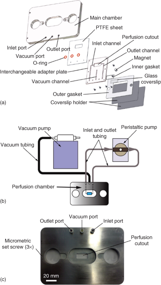
Figure 8.1 Organotypic brain slice perfusion chamber design. Depicted in this figure is the design for the perfusion chamber of the organotypic slices. The perfusion chamber is compatible with the approach of a microfluidic probe from the top and a microscope objective from the bottom. It is designed to accommodate standard  coverslips and interfaces with a vacuum pump to hold everything in place as well as a peristaltic pump for cycling of media. (a) Blowout diagram depicting each of the individual parts used in the perfusion chamber, and the order of their assembly. (b) Depiction of the tubing inlets and outlets for the vacuum and pump lines. (c) Photograph of the assembled chamber to give an idea of scale.
(Queval et al. (2010) [22]. Copyright 2010. Reproduced with permission of the Royal Society of Chemistry.)
8.2.2 Design of PDMS MFP
To make an MFP with a smaller footprint – so that a larger range of lateral motion could be obtained in the perfusion chamber – previous MFPs were redesigned and this time were made entirely out of PDMS. The PDMS MFPs were made using soft lithography to make two identical PDMS pieces, followed by bonding these pieces together with a thin membrane of PDMS in between the pieces (Figure 8.2a).

Figure 8.2 Six-channel microfluidic probes. The fabrication process used to make the six-channel microfluidic probes. (a) Photoresist is spun onto a silicon wafer and exposed to UV light through a photomask, followed by development to form the master mold. PDMS blocks containing the channels for the microfluidic probes are made by partially curing PDMS on the silicon wafer mold. PDMS blocks are removed and access holes are drilled. A thin membrane of PDMS is partially cured on a flat silicon wafer, after which one of the patterned PDMS blocks is cured on top of it. A second patterned PDMS block is aligned and cured to the other side of the thin membrane. When the PDMS is fully cured, the probes are cut out. (b) A finished six-channel microfluidic probe. (c) Image of the six channels at the end of the microfluidic probe. (d) The channel size may be altered by using a different silicon wafer master mold, created with a different photomask.
(Queval et al. (2010) [22]. Copyright 2010. Reproduced with permission of the Royal Society of Chemistry.)
The molds for the identical PDMS pieces were made using standard processes for microfluidic mold generation. Briefly, SU8-25 was spun onto a four in wafer to make a 40 µm layer of resist. This resist was exposed using a mask aligner and a photomask and developed with SU8 developer to generate 40 µm thick features in the SU8. This mold was activated with air plasma and silanized using trichlorofluorosilane to prevent the PDMS from sticking to the mold during the subsequent soft-lithography replication steps. To replicate the SU8 patterns in PDMS, Sylgard 184 was mixed at a 1 : 10 ratio and poured on the mold, which was placed in the bottom of a Petri dish. To make the full probe structure at one time, PDMS was only partially cured in two of these identical molds simultaneously (about 30 min in a 60° oven) before being removed from the mold. Access holes for each channel were drilled into the PDMS block using a 280 µm diameter drill bit. At the same time, a very thin layer of PDMS was spin coated onto a clean silicon wafer (1800 rpm for 30 s, resulting in 40 µm thick layer) and baked at 60° for 10–15 min, again so it was only partially cured. One of the partially cured molded PDMS blocks was pressed against the partially cured thin PDMS film and cured a further 5 min at 60°. Next this structure was flipped over and the second molded block of PDMS was first aligned using a stereo microscope and pressed against the back side of the thin membrane and baked for another 24 h at 65° to fully bond the layers. Finally the individual probes were cut from the bonded PDMS blocks into their final shapes, seen in Figure 8.2b.
Using this fabrication process, it was possible to make 10 MFPs in one day, once the master mold was made in the clean room. After the initial master mold fabrication, clean-room fabrication was not necessary to produce these probes. One master mold could be used many times to produce many probes, and even a single probe could be used multiple times for different experiments, demonstrating that this fabrication process has quite high throughput for the purposes of these experiments. The advantage of bonding the layers via partially cured PDMS, over the more conventional practice of oxygen plasma bonding, is that this bonding is reversible, at least until the curing process is completed. This allows for small corrections to be made if the probe channels are initially misaligned with each other, which would not be possible with oxygen plasma bonding [26].
The MFPs made in this work featured six aperture channels, rather than the commonly reported two channel MFPs or the four channel microfluidic quadrupoles in other work [23, 27, 28]. Each PDMS block molded from the SU-8 master had three channels, and two blocks together, separated by the 40 µm membrane of PDMS, made a single probe. Having six channels in the MFP allows for a large number of hydrodynamically confined flow profiles, depending on which channels are set to inject, aspirate, or remain inactive. Some of these numerous flow profiles were tested experimentally with the six-channel probe using 10 nL/s as an injection rate and 100 nL/s as an aspiration rate. These may be seen in Figure 8.3. These injection and aspiration rates could be adjusted to obtain different flow profiles by changing the absolute injection and aspiration rates together or by changing the ratio of the injection to aspiration rate. Additionally, the mold for making the PDMS MFPs could be changed to make different channel widths and depths, and the thickness of the separating membrane could be changed to generate a wide variety of different probe geometries. For example, for the microperfusion experiments, the MFP specifications were slightly different than those used for the flow profiling seen in Figure 8.3. The channels were 40 µm deep and 70 µm wide, separated by a 55 µm membrane (instead of a 40 µm membrane), with an injection rate of 5 nL/s and an aspiration rate of 25 nL/s (instead of 10 and 100 nL/s, respectively).
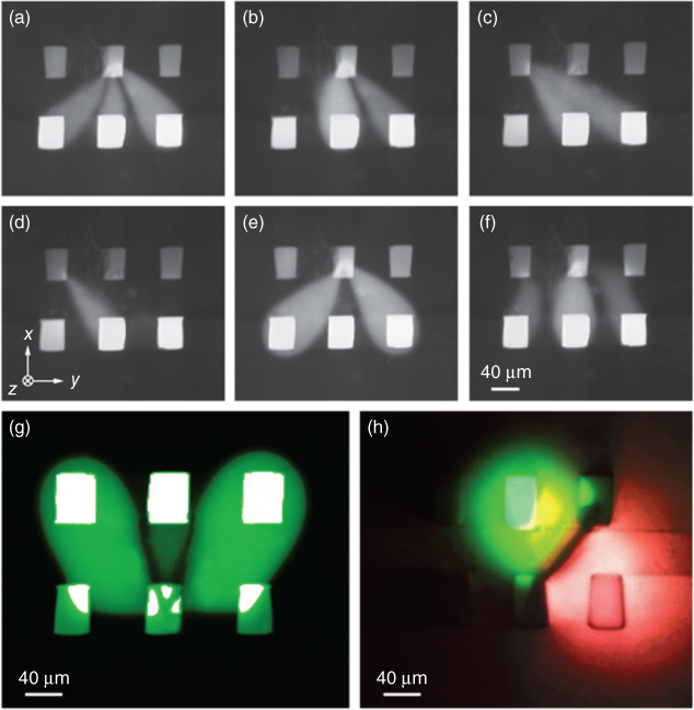
Figure 8.3 Six-channel MFP flow profiles. Demonstration of the wide variety of possible hydrodynamic flow confinement patterns made possible by using a six-channel microfluidic probe. There are 726 different possible flow patterns using each of the six channels for injection, aspiration, or neither. A variety of these combinations are seen in (a–g). It is also possible to use multiple dyes or reagents at the same time – in (h), two dyes are used simultaneously. The black line between the dyes occurs because of the two dyes diffusing together and quenching each other.
(Queval et al. (2010) [22]. Copyright 2010. Reproduced with permission of the Royal Society of Chemistry.)
Organotypic brain slices are sensitive to shear stresses, which must be considered when designing a localized perfusion system for these samples – indeed, shear stress is often a consideration when designing microfluidic systems for biological applications [29]. To investigate this concern more completely, a finite element model was created to calculate the shear stress on the sample surface when exposed to this six-channel probe. The model results demonstrate that, for constant flow rates, the shear stress at the surface of the tissue sample decreases quadratically as the gap between the probe mesa and the substrate increases (Figure 8.4). The model also demonstrated that decreasing the injection and aspiration flow rates, or increasing the aperture size, can also decrease the shear stress at the sample surface (data not shown). Models such as these are useful for designing experiments where shear stress is a concern and may be used to design the system in order to keep expected shear stress below a certain level.
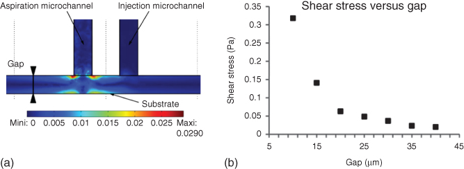
Figure 8.4 FEM results. Finite element modeling of injection and aspiration channels to determine shear stress on a sample due to the microperfusion. As the gap between the MFP mesa and the substrate decreases, the shear stress on the substrate surface due to the injected fluid increases. Increasing the aperture sizes or decreasing the injection and aspiration flow rates will also decrease the shear stress applied to the substrate surface (data not shown).
(Queval et al. (2010) [22]. Copyright 2010. Reproduced with permission of the Royal Society of Chemistry.)
8.2.3 Microscope Setup
An inverted Nikon confocal microscope was used for the experiments shown here. The MFP was attached to a micromanipulator, which was in turn screwed directly into the microscope platform. Precision syringe pumps were connected to each of the six MFP lines to control the injection and aspiration rates of each channel. Custom LabVIEW software [30] was used to control the micromanipulator and syringe pumps.
8.2.4 Microperfusion of Organotypic Brain Slices
To demonstrate the utility of the perfusion chamber and the PDMS MFP with a smaller footprint than previously demonstrated MFPs, 400 µm thick hippocampal brain slices from 6-day-old mice were prepared using the roller drum technique, as described earlier. The slices were maintained for 2–4 weeks before use when they were transferred from the roller tubes to the perfusion chamber and mounted on the microscope stage. For these experiments, a line of variegated mice was generated that expressed a consistent number of membrane-bound green fluorescence protein (mGFP)-labeled cells within the CA1 of the hippocampus. Once within the custom perfusion chamber, the slices were continuously perfused with a Tyrode solution described in Queval et al. [22]. The MFP was positioned 90 µm above the surface of the coverslip, which results in about a 20 µm gap between the MFP and the tissue sample (a 400 µm brain slice will shrink to approximately 70 µm during roller tube culture [4]). To confirm the shear stress modeling, a perfusion injection rate of 10 nL/s and an aspiration rate of 100 nL/s were used with no signs of cells detaching. To test the depth of perfusion into the sample, however, rates of 5 and 25 nL/s were used, respectively, with the change in injection to aspiration rate ratio, resulting in a larger hydrodynamic flow profile and deeper perfusion into the sample. The hydrodynamic confinement profile was 114 µm long and 83 µm wide in this case. An illustration of the overall experimental setup, as viewed from the side, may be seen in Figure 8.5.

Figure 8.5 Integrated perfusion chamber with microfluidic probe. (a) A side view depiction of the experimental setup used for microperfusion of organotypic brain slices. (b) An exploded view of the interface between the microfluidic probe and the sample.
(Queval et al. (2010) [22]. Copyright 2010. Reproduced with permission of the Royal Society of Chemistry.)
The brain slices were perfused with red dextran for 25 min and were imaged in confocal slices with a spacing of 5.4 µm. It was found that in this time the dextran penetrates 32 µm into the 70 µm brain slice, with a volume encompassing about 25 cells, using the flow parameters described earlier. For imaging, an Argon laser line at 488 nm was used to excite the mGFP and image the neurons, while a HeNe laser at 639 nm was used to excite the fluorescent dextran. A 403 nm laser was used to image the nuclei of the cells, stained with DAPI (Figure 8.6).

Figure 8.6 Microperfusion of brain slice with microfluidic probe. Results from the microperfusion experiments using the microfluidic probe with an organotypic brain slice. The injection rate was 5 nL/s and the aspiration rate was 25 nL/s. Nuclei are stained in blue with DAPI, while the microfluidic probe was used to locally perfuse the brain slice with red dextran (10 kDa, Alexa-647). The mesa of the MFP is 25 µm above the sample, and perfusion time is 25 min. The dye penetrates 32 µm into the sample.
8.3 Microperfusion of Live Dissociated Neural Cell Cultures Using the Microfluidic Probe
While perfusion of the hippocampal brain slice with red fluorescent dextran was a useful example of the capabilities of this perfusion chamber and MFP, this example utilized brain slices, which were fixed and stained, for easy visualization of the cell nuclei, because the intent of this experiment was primarily to be used as a proof of concept. However, the perfusion chamber that was discussed earlier was developed to be used with live samples. In this section, we present other applications of microperfusion using an MFP, primarily for living cells cultured in the previously described perfusion chamber. The MFP was used to selectively stain single axons with DiI for visualization (Figure 8.7) and to perfuse the axon of a neuron with FluoroMyelin, a chemical that is selectively bound to the myelin encasing the axon (Figure 8.8) [24]. While these examples pertain to dissociated neurons cultured in vitro, the same technique may be used with brain slices, for example, as a way to selectively stain myelin in an organotypic slice and therefore study the myelination of neurons within the slice. Myelination of neurons is an interesting area of study, and research relating to axon myelination [31] could be enhanced by adopting the microperfusion technology shown here.


Figure 8.7 Selective staining of a single axon with DiI using the MFP. In this example, commissural neurons were cultured on protein stripes that were micro-contact printed in a dish. A single neuron was selected for staining and labeled using DiI. The perfusion time was 15 min, with a 50 µm gap between the mesa and the substrate, an injection flow rate of 10 nL/s, and an aspiration flow rate of 100 nL/s. (a) Arrows point to live neurons before the experiment. (b) The same neurons are present after the perfusion experiment. (c) Only the selected neuron in the middle is labeled, while the others remain untouched. (d) High magnification image of the labeled neuron.
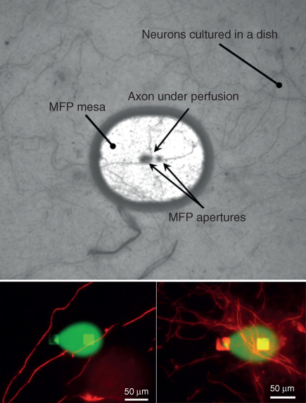
Figure 8.8 Perfusing axons with FluoroMyelin. The MFP was used to locally perfuse a fixed culture of dorsal root ganglia neurons with a solution of FluoroMyelin to study axonal myelin. The solution is mixed with Fluorescein for visualization (central areas in the bottom insets). Neurons were stained with the myelin basic protein MPB (bright filaments and areas around the confined solution) for labeling myelin.
Another example of the potential applications for this technology was demonstrated when an MFP was used to selectively perfuse a section of the axon of a live hippocampal neuron with tumor necrosis factor-α (TNFα) [24]. TNFα is commonly applied to a whole culture of neurons as a bath application and is used to regulate synaptic transmission [32]. Again, this particular experiment was performed on dissociated primary cell cultures, rather than brain slices, but the ability to locally regulate synaptic transmission in hippocampal organotypic brain slice cultures with a perfusion of TNFα through the MFP would be an interesting application of the microperfusion technology demonstrated here.
In addition to the previous examples, a vertical microfluidic probe (vMFP) has been used to perform micro-immunohistochemistry on tissue slices [33], which is another effective demonstration of the utility of this noncontact probe technology with tissue samples. This work is described in Chapter 6 and so will not be discussed here. The previous examples show that microperfusion using the MFP, as presented in this chapter, could be adapted to many useful experiments in the field of neuroscience.
8.4 Conclusion
In this chapter, we presented an extension of MFP technology into the field of neuroscience, with an emphasis on microperfusion of hippocampal organotypic brain slice cultures and dissociated neuronal cell cultures. The common roller tube culture technique was used to culture the brain slices because it allows for the thinnest organotypic slices and the longest slice survival in vitro. A perfusion chamber was developed to be compatible with (i) standard roller tube cultures, (ii) an MFP approaching the sample from above, and (iii) high numerical aperture inverted microscopy for imaging from below. New MFPs were designed and fabricated entirely of PDMS using a simple fabrication process that produced probes with six openings on the mesa. The effectiveness of this setup was demonstrated by perfusing red dextran dye into a fixed hippocampal slice to a depth of 32 µm over 12 min. In addition, several experiments utilizing the MFP to perfuse dissociated neurons in culture were presented to illustrate that different reagents may be used to adapt this technology to multiple other neurological studies. Example applications of this technology were presented: (i) perfusion of DiI for visualization of live single neurons (Figure 8.7), (ii) perfusion of FluoroMyelin to investigate myelination (Figure 8.9), and (iii) perfusion of TNFα for synaptic regulation in live neurons (Figure 8.9). Future applications of this technology include the localized microperfusion of live organotypic brain slices for drug application studies or investigation of synaptic plasticity in live tissue slices.

Figure 8.9 Perfusing neurons with TNF. The MFP was used to locally perfuse rat hippocampal neurons with TNF solution for synaptic plasticity studies. The solution is mixed with red dextran for visualization. The glutamate receptors type 1 (GluR1) are labeled green following transfection of neurons with pHluorin-GluR1.
Acknowledgments
NSERC and CIHR are acknowledged for funding. DM acknowledged an NSERC fellowship and DJ a Canada Research Chair. We thank David Stellwagen for pHluorin-GluR1 transfected neurons.
References
- 1 Cho, S., Wood, A., and Bowlby, M.R. (2007) Brain slices as models for neurodegenerative disease and screening platforms to identify novel therapeutics. Curr. Neuropharmacol., 5, 19–33.
- 2 Gähwiler, B.H., Capogna, M., Debanne, D., McKinney, R.A., and Thompson, S.M. (1997) Organotypic slice cultures: a technique has come of age. Trends Neurosci., 20, 471–477.
- 3 Stoppini, L., Buchs, P.-A., and Muller, D. (1991) A simple method for organotypic cultures of nervous tissue. J. Neurosci. Methods, 37, 173–182.
- 4 Gähwiler, B.H. (1981) Organotypic monolayer cultures of nervous tissue. J. Neurosci. Methods, 4, 329–342.
- 5 Geng, X. and Mori, M. (2015) Monosynaptic excitatory transmission from the hippocampal CA1 region to the subiculum. Neurosci. Lett., 604, 42–46.
- 6 Maysinger, D. et al. (2015) Dendritic polyglycerol sulfate inhibits microglial activation and reduces hippocampal CA1 dendritic spine morphology deficits. Biomacromolecules, 16, 3073–3082.
- 7 van Midwoud, P.M., Merema, M.T., Verpoorte, E., and Groothuis, G.M.M. (2010) A microfluidic approach for in vitro assessment of interorgan interactions in drug metabolism using intestinal and liver slices. Lab Chip, 10, 2778–2786.
- 8 van Midwoud, P.M., Groothuis, G.M.M., Merema, M.T., and Verpoorte, E. (2010) Microfluidic biochip for the perifusion of precision-cut rat liver slices for metabolism and toxicology studies. Biotechnol. Bioeng., 105, 184–194.
- 9 Rambani, K., Vukasinovic, J., Glezer, A., and Potter, S.M. (2009) Culturing thick brain slices: an interstitial 3D microperfusion system for enhanced viability. J. Neurosci. Methods, 180, 243–254.
- 10 van Midwoud, P.M., Merema, M.T., Verpoorte, E., and Groothuis, G.M.M. (2011) Microfluidics enables small-scale tissue-based drug metabolism studies with scarce human tissue. J. Lab. Autom., 16, 468–476.
- 11 Tang, Y.T., Kim, J., López-Valdés, H.E., Brennan, K.C., and Ju, Y.S. (2011) Development and characterization of a microfluidic chamber incorporating fluid ports with active suction for localized chemical stimulation of brain slices. Lab Chip, 11, 2247–2254.
- 12 Kim, M.S. et al. (2010) Breast cancer diagnosis using a microfluidic multiplexed immunohistochemistry platform. PLoS One, 5, e10441.
- 13 Mauleon, G., Fall, C.P., and Eddington, D.T. (2012) Precise spatial and temporal control of oxygen within in vitro brain slices via microfluidic Gas channels. PLoS One, 7, e43309.
- 14 Chang, T.C. et al. (2014) Parallel microfluidic chemosensitivity testing on individual slice cultures. Lab Chip, 14, 4540–4551.
- 15 Huang, Y., Williams, J.C., and Johnson, S.M. (2012) Brain slice on a chip: opportunities and challenges of applying microfluidic technology to intact tissues. Lab Chip, 12, 2103–2117.
- 16 Sun, M., Kaplan, S.V., Gehringer, R.C., Limbocker, R.A., and Johnson, M.A. (2014) Localized drug application and sub-second voltammetric dopamine release measurements in a brain slice perfusion device. Anal. Chem., 86, 4151–4156.
- 17 Choi, Y., McClain, M.A., LaPlaca, M.C., Frazier, A.B., and Allen, M.G. (2007) Three dimensional MEMS microfluidic perfusion system for thick brain slice cultures. Biomed. Microdevices, 9, 7–13.
- 18 Veselovsky, N.S., Engert, F., and Lux, H.D. (1996) Fast local superfusion technique. Pflügers Arch., 432, 351–354.
- 19 Ahemaiti, A. et al. (2013) A multifunctional pipette for localized drug administration to brain slices. J. Neurosci. Methods, 219, 292–296.
- 20 Ainla, A., Jeffries, G.D.M., Brune, R., Orwar, O., and Jesorka, A. (2012) A multifunctional pipette. Lab Chip, 12, 1255.
- 21 Ainla, A., Jeffries, G., and Jesorka, A. (2012) Hydrodynamic flow confinement technology in microfluidic perfusion devices. Micromachines, 3, 442–461.
- 22 Queval, A. et al. (2010) Chamber and microfluidic probe for microperfusion of organotypic brain slices. Lab Chip, 10, 326–334.
- 23 Juncker, D., Schmid, H., and Delamarche, E. (2005) Multipurpose microfluidic probe. Nat. Mater., 4, 622–628.
- 24 Qasaimeh, M.A., Ricoult, S.G., and Juncker, D. (2012) Microfluidic probes for use in life sciences and medicine. Lab Chip, 13, 40–50.
- 25 Guillaume-Gentil, O., Zambelli, T., and Vorholt, J.A. (2013) Isolation of single mammalian cells from adherent cultures by fluidic force microscopy. Lab Chip, 14, 402–414.
- 26 Sunkara, V. et al. (2011) Simple room temperature bonding of thermoplastics and poly(dimethylsiloxane). Lab Chip, 11, 962–965.
- 27 Qasaimeh, M.A., Gervais, T., and Juncker, D. (2011) Microfluidic quadrupole and floating concentration gradient. Nat. Commun., 2, 464.
- 28 Kaigala, G.V., Lovchik, R.D., Drechsler, U., and Delamarche, E. (2011) A vertical microfluidic probe. Langmuir, 27, 5686–5693.
- 29 Velve-Casquillas, G., Le Berre, M., Piel, M., and Tran, P.T. (2010) Microfluidic tools for cell biological research. Nano Today, 5, 28–47.
- 30 Perrault, C.M. et al. (2010) Integrated microfluidic probe station. Rev. Sci. Instrum., 81, 115107.
- 31 Liazoghli, D., Roth, A.D., Thostrup, P., and Colman, D.R. (2012) Substrate micropatterning as a new in vitro cell culture system to study myelination. ACS Chem. Neurosci., 3, 90–95.
- 32 Stellwagen, D. and Malenka, R.C. (2006) Synaptic scaling mediated by glial TNF-α. Nature, 440, 1054–1059.
- 33 Lovchik, R.D., Kaigala, G.V., Georgiadis, M., and Delamarche, E. (2012) Micro-immunohistochemistry using a microfluidic probe. Lab Chip, 12, 1040–1043.