
Chapter 9
The Multifunctional Pipette
Aldo Jesorka and Irep Gözen
Chalmers University of Technology, Biophysical Technology Laboratory, Department of Chemistry and Chemical Engineering, Kemivägen 10, 41296 Göteborg, Sweden
9.1 Introduction
Microfluidic technology is a dynamic and diverse area of research and development of miniaturized flow devices, which in most cases employ micrometer-sized channel systems to move fluid in various ways. One might possibly pinpoint the origin of this technology to the ink-jet printing device introduced by Swedish engineer Rune Elmqvist of the German company Elema, later Siemens AG, in 1948. In this miniaturized fluid delivery concept, droplets are formed from an ejected ink stream at a microsized opening in close proximity to the surface of a sheet of paper. The drop formation occurs, primarily as a result of surface tension, by a stream breakup mechanism discovered in 1873 by Joseph Plateau and little later analytically explained by Lord Rayleigh [1]. Nearly 30 years later, the ink-jet printer became also the first commercially available microfluidic device, introduced to the market in June 1976 by IBM. Ink-jet printing, practically a concealed “open volume” microflow technology, is to date the most successful commercial microfluidic application, even though lab-on-a-chip applications in routine chemical analysis and life science have started to grow massively in numbers.
Today, microflow devices for handling and processing of micro- to picoliter volumes of liquids play a significant role in, or even already dominate, sample treatment and analysis in molecular biology, proteomics, DNA research, and chemical analysis. The efforts in confining small volumes of chemical and biological material to microchannels are mainly made due to the need to reduce sample size and reagent consumption in order to lower the costs per operation. In addition, versatile microdevice fabrication protocols adapted from the semiconductor industry have enabled the fabrication of integrated devices for combining of fluid processing steps, such as dilution, mixing, binding, washing, and digestion, to effectively create entire “labs on a chip.” The most highly integrated variants are the micro-total-analysis systems (µTAS), which typically combine miniaturized on-chip detection schemes with sample processing and analyte separation units.
The channel structures of microfluidic devices are commonly fabricated through a semiconductor industry-derived top-down micro-construction approach: A pattern definition step by optical lithography on quartz, silicon, or glass substrates is followed by one or more of the various standard deposition or etching techniques. Alternatively, soft lithography is typically used in prototyping, often using the silicon elastomer polydimethylsiloxane (PDMS). The thus generated channels are closed by a material-specific bonding procedure, which caps the channel-bearing device surface with a lid. There are also layer-by-layer fabrication technologies, for example, utilizing paper or polymer thin films [2]. Closed-channel microfluidics is without doubt an accepted, and often well-established, operation concept in chemistry and life science research [3] and has already gained traction in personalized and low-cost medical diagnostics [4]. More recent technological developments, such as droplet microfluidics [5], and the perpetual progress in low-cost production processes, are expected to decrease the barrier for microfluidic device application and simultaneously drive technology development further into more diverse application areas.
In some instances, closed channel microfluidic devices do not provide feasible solutions to the practical problems faced in the laboratory, even though sample requirements like concentration and volume might in the optimal range. It is, for example, difficult or often impossible to apply patch clamp needles, electrodes, or other probes effectively to cells inside fluidic chips or to interact with functionalized surfaces or surface-adhered objects, which include adherent single cells or tissue slices. Biological cells need to be removed from their native culture environment in order to be introduced into a microfluidic channel structure, manipulated to the desired position, kept alive under the conditions of the desired experiment, and finally often transferred subsequently for further manipulation. As an alternative, special chip environments have been created, where cells can be cultured or tissue samples nourished inside. However, growing cells inside microscale channels is also subject to numerous limitations, for example, the diffusion-dominated material transport in confined volumes, which can have a detrimental effect on cell health.
Moreover, the desire for controlled delivery of small amounts of liquid to a well-defined surface area, for instance, in order to create periodic surface patterns or achieve locally confined surface functionalization, pushes closed channel designs to the limit.
Open volume technology, essentially constituting an open interface between channel exits at the edge of a chip, a large surrounding fluidic volume, and an object of interest placed in between, has been found to be an acceptable solution to some of the problems. In this way, rapid solution exchange around biological cells became possible, which was welcomed in particular by the pharmacological community interested in ion channel studies. “Lab-on-a-chip” systems were commercially introduced with up to 96 parallel channels [6]. Such chemical waveform generators were able to expose cells to rapidly changing chemical environments, where exchange times of 20–100 µs could be reached. This technology was successful in the pharmaceutical sector, as it facilitated the determination of dose–response relationships of ion channels in single cells tremendously.
From there it was only a short road to the next generation of microfluidic devices, which employ hydrodynamically confined flow (HCF) technology in order to create a unique fluidic environment around an object of interest. The idea of a temporarily generated separate chemical environment around a single cell in its native culture environment was not entirely new; puffer pipettes had been in existence for quite some time [7]. These glass needles, filled with a solution of active compounds and connected to a low volume pump, could repeatedly send puffs of the active solution across a selected cell in a highly localized manner. Their major benefit was the ability to position the injection site very close to the object of interest. Problems remained with respect to the fragility of the needles, buildup of injected solution over time, inflexibility with respect to multiple components to be applied sequentially, and others. The continuous injection problem was nicely addressed with the “fast local superfusion” concept, which employed two closely spaced needle tips. The breakthrough came in 2004, when hydrodynamic flow confinement, an elegant, contamination-free open volume concept, was presented using coaxial glass needles (Figure 9.1a) [8] and implemented for the first time in a microfabricated fluidic device in 2005 [9]. A variety of different HCF devices appeared in the literature in rapid succession [10–13], including the microfluidic pipette [14] and its successor, the multifunctional pipette [15].

Figure 9.1 The double-barrel coaxial pipette, ancestor of the multifunctional pipette, and the flow profile in the corresponding planar two-channel microfluidic device. (a) Schematic drawing of the tip of a coaxial double-barrel glass needle, and the recirculating flow that is generated at the tip if a fluid stream is injected through the inner needle and simultaneously aspirated through the outer needle. (b) Fluorescence micrograph capturing the recirculating flow of a dilute fluorescein solution from a simple microfluidic device with two parallel channels (channel dimensions 35 × 35 µm, separated by a 15 µm thick wall, flow velocity: 25 nL/s) through an open volume form the top. The arrows (right) depict the flow field of the fluid aspirated into the inlet channel (top) and the arrows (left to right) the flow of the injected fluid, consisting of a 0.1 mM fluorescein solution in water. The asymmetric, teardrop-like shape of the recirculated volume is typical for two-channel setups. The fluorescence intensity profile across of the upper channel shows that besides the recirculated fluorescein solution, a share of the external volume is also aspirated into the device. Vasp, aspiration vacuum; Pinj, injection pressure.
9.2 Open Volume Probes
In most practical cases, bulk solutions are homogenous, or perfectly mixed, meaning that the concentrations of all constituents of a solution are approximately the same in any given volume element. As briefly introduced in the previous section, it is on occasion interesting to locally create inhomogeneity conditions in a given volume, for example, around a cell immobilized on a patch clamp pipette or a group of adherent cells on a surface or on a desired area at the surface of a tissue slice. It is clear that microfluidic technology is particularly strong at creating small volume fractions of a fluid, although in closed-channel devices this is isolated from the remainder of the fluid through the boundary of the channels. The earlier mentioned puffer pipettes are a technical work-around that only temporarily combats the diffusive equilibration of concentration differences, however, often long enough to achieve the desired results, for example, the activation of ligand-gated ion channels in a cell exposed to the puff of an activating ligand.
More versatile in its capabilities is a microfluidic representation of the puffer pipette – the parallel-flow chip featuring several interacting fluid streams exiting an array of adjacent microchannels. In the laminar regime typical of microfluidic devices, the exiting flows flow side by side, but do not mix readily. Separated fluid streams coexist in the open volume for several tens of micrometers before diffusively equilibrating. Within this range, the exiting streams are readily accessible from the open volume and have consequently been used to change the solution environment around individual cells, most importantly for the purpose of exposing these cells to concentration gradients of an ion channel antagonist. Single cells are typically picked up by means of a patch clamp pipette, so that simultaneous recording of ion channel activity is possible and micromanipulated into the vicinity of the channel array. Programmed movement of the linear array by means of an automated stage exposes the cells in rapid succession to different chemical stimuli. Such exposure experiments are tremendously important for the determination of dose–response relationships, which characterize the effectiveness of a pharmaceutical with respect to its action on an ion channel. Parallel channel devices of this type can generate patterns of laminar flows, or concentration landscapes, of single or multiple compounds. These systems can be accurately simulated by finite element methods; experimental and simulation data have been shown to be in good agreement [16, 17].
Semi- or fully automated labs-on-a-chip have since been developed for dose–response measurements, which process suspended cells, immobilize them in predesigned region, and perform high throughput patch clamp measurements under closed channel conditions [6]. In other cases, where it is necessary to work with adherent cells, or tissue samples, neither the automated systems nor the parallel channel devices constitute a satisfactory solution. Neither of these devices can approach the desired cells to a distance of a few micrometers and perform the solution exchange in their vicinity. The laminar pattern generator has an additional problem, the progressive buildup of the active compound concentration in the open volume, as well as a need to physically move the device outlets (essentially the entire chip device) to deliver concentration patterns.
This is where the specific advantages of HCF technology can be utilized. In an array of two or more adjacent channels, one channel serves as injection port or outlet, where liquid is introduced into the open volume, and one or more serve as aspiration port or inlet, through which liquid is simultaneously removed from the open volume. Since a share of the open volume fluid is also being removed from the fluid bulk, a laminar flow envelope results, which confines the injected liquid between inlet and outlet (Figure 9.1b).
All HCF devices make use of the efficient confinement of one solution in another, actually miscible, solution. As presented in earlier chapters, a number of different HCF devices, each with their individual strengths and features, have been developed and validated in various experimental settings. Their number and level of sophistication can be expected to grow further in the future, as this class of new open volume probes has just started to progress into an independent research field.
This chapter is dedicated to the multifunctional pipette, a hydrodynamically confined volume device that has been specifically developed for single-cell superfusion in adherent cultures. It is in many aspects related to the idea behind the coaxial double barrel needle but makes use of the unique functional options and the fabrication technology portfolio offered by modern microfluidic chip devices. Ideally, a pipette should not only be easily moved from target to target but also allow for successive injections of different solutions, without (i) the need to exchange or refill the needle and (ii) significant buildup of the injected solutions in the open volume around the cells. The multifunctional pipette was designed with these criteria in mind and achieved a good compromise between the size constraints imposed by the fabrication techniques on one hand and the desired user-friendliness, ruggedness, and multifunctionality on the other. The superfusion of cells, for which the pipette was predominantly developed, turned out to be merely an enveloping concept; this device has been investigated under a variety of different aspects. The design features, aspects of fabrication and deployment, and various application examples are presented in this chapter. More detailed application notes in the area of single-cell analysis are covered in a separate chapter.
9.3 Detailed View on the Multifunctional Pipette
9.3.1 Chip Concept
A direct analogue of the initial elegant and groundbreaking coaxial pipette design (Figure 9.1a), generated by means of microfabrication techniques, has not yet been reported. Fabrication of a channel inside another channel without “unconventional” process steps is a considerable challenge. Such 3D (three-dimensional) architecture would require fabrication processes that diverge from today's standard layer-based two-dimensional (2D) approaches of semiconductor fabrication, upon which microfluidic chip technology still largely relies. However, the currently established and widespread designs of linear, side-by-side channel arrays perform well enough to make highly functional HCF devices with very good control over the virtual flow chamber possible [9–15]. Especially the more advanced “flow-in-flow” enveloping concepts have been able to reduce the size of the HCF volume to a range that comes close to the performance of the coaxial pipette [18].
The multifunctional pipette is a microfluidic device with three parallel open channels, which are used to create the hydrodynamically confined volume, concentrated at the tip of a pointed, pen-like structure consisting entirely of PDMS (Figure 9.2a). The microfluidic channel structures, prepared by soft lithography using a silicon master, sit on the bottom plane of the device, not more than a few tens of micrometer away from the surface. The 10–30 µm thin bottom plane allows close proximity of the channel exits to the surface (Figure 9.2b and c). The thin bottom, prepared by bonding a thin PDMS membrane to the replica-molded pipette body, is a specific structural feature of the device, which distinguishes it from all other currently available HCF devices. A three-channel design was chosen in order to produce a more symmetrical HCF (Figure 9.2d), as compared with the teardrop-shaped HCF typical for two-channel arrangements (Figure 9.1a).
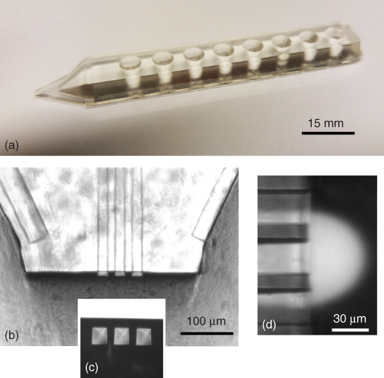
Figure 9.2 The main features of the multifunctional pipette with its three side-by-side channels. (a) Side view of the PDMS pipette body after assembly and tip cutting. Eight 35 µL on-chip wells function as reservoirs for solution outflows and for inflows of the recirculated fluids. The channels are located in the bottom plane of the device. Panel (b) shows the shaped tip of the device. The inset (c) is a micrograph in “bottom-up” configuration of the front face of the channel outlets, highlighting the thickness of the bottom layer. This layer is approximately of the same dimension as the channels, allowing positioning of the channel outlets very close to the surface. Panel (d) is a mixed brightfield/fluorescence micrograph of recirculating fluorescein solution in front of the channel outlets, depicting the operation state of the pipette. The image illustrates the co-flow of aspirated external volume with the fluorescein solution, which is drawn into the aspiration channels on both sides of the injection channel.
The pipette is, like most of the other HCF devices, a free-standing tool, which is in contrast to the earlier generation of open volume devices with parallel channels leading into a device-integrated open volume [16]. The point of exposure can be set by positioning the device with its tip in the close vicinity of the object of interest, for example, next to a single cell in an adherent cell culture or even beside a selected part of a cell, such as the axonal or dendritic region of a neuron, or a part of a suspended muscle fiber (Figure 9.3a) [19].

Figure 9.3 Device design and operation of the multifunctional pipette. (a) The simplest implementation of the multifunctional pipette concept. A PDMS body contains three wells, one connects to the injection channel (dark gray) and two for waste collection to either aspiration channel (light gray). The tops of the wells are connected to air pressure/vacuum sources, which drive the flows through the channels. At the bottom of the device, channels of equal length are positioned, leading from the wells to the sharp tip of the pipette. The device is mounted on a handle, which allows positioning of the pipette by means of a micromanipulator to objects of interests, such as single cells. Pressures are adjusted in the proper range to form a recirculation volume (virtual flow cell) at the tip of the device. (b) More advanced channel system, which incorporates a flow switching chamber, marked with an (*), which allows for switching between three different solutions (green and red color for active and inactive solution). Two additional vacuum wells and channels (orange color) are needed for proper function of the flow switch. They are independent from the recirculation vacuum wells and channels (blue color). The adjustment paths to equalize the channel lengths, which can be seen in (a), have been omitted here. (c) Most recent pipette design in a long pen-shaped format with wells supporting four individual solutions. The switching chamber is positioned approximately 1 mm away from the channel outlets. A dampening well between tip and reservoirs was added to reduce the effect of expansion and contraction of the device along its long axis upon pressure change.
9.3.2 Device Design and Function
The simplest design of a pipette with these features would require only three ports, one for the active solution to be injected and two for the recirculation inflows on either side of the injection channel. This design was published in 2010 [14], and it did not have the on-chip wells that are shown in the figure, but tubes connected to external reservoirs, with the flows driven conventionally by syringe or peristaltic pumps. The associated large dead volume problem and the inconvenient procedure of connecting and disconnecting of port lines, which also bears the risk of cross-contamination, led to the development of the on-chip wells, serving as either solution reservoirs or waste collection wells for the recirculation inflow. Figure 9.3a displays schematically the 3-well version, where the flow is driven through the channels by two air pressure sources, one positive for the outflow and one vacuum source for aspirating the solution through the side channels back into the chip. In order to have precisely defined flow conditions, all channels were designed with exactly the same length, meaning that loops of appropriate lengths were inserted into the channels connected to the wells that are positioned closer to the tip. The figure shows further the concept of positioning the pipette to the targets, using one of the many different commercially available electrically or manually driven 3-axis micromanipulators.
This simple concept fulfills the requirement of contamination-free exposure of single cells, where buildup of injected solution in the open volume is effectively suppressed, but it is still not possible to switch between different injected solutions without removing the device from the solution. For that reason, an on-chip switching device was devised, which can easily be fabricated together with the channels. In principle, the Quake valves could be implemented, but this would require an extra layer of control channels, which complicates fabrication and ultimately limits the material choices to elastomeric materials. Implemented was finally the simpler flow steering principle that had earlier been employed in a microfluidic fraction collector [20]. Here the desired stream is guided by parallel streams driven by differential pressures in support channels. However, this requires that, during pipette operation, flows are continuously driven from all reservoirs, so that cross-contamination due to molecular diffusion between resting solutions is prevented. The channel layout for the device capable of switching between three different on-chip solutions is displayed in Figure 9.3b. Of the three fluid streams entering a switching chamber close to the channel outlet to the open volume, the selected (active) one is driven at higher flow velocity than the other two, which act as (inactive) steering streams. The flow switching chamber requires two additional outflow channels, leading from the switching chamber to two additional wells, which are connected to a vacuum source. The steering streams, flowing at much lower velocity, are drawn into these channels. The function of the switching chamber is explained in more detail in one of the following subsections (Figure 9.6). The support, or switch vacuum wells, can be connected to the same vacuum source, if defined flow conditions are ensured, requiring that all channels have equal length (Figure 9.7).
This much improved prototype design, which meets the essential demands on a microfabricated pipette analogue already well, was further refined to its current state with four individual supply wells and a narrow body with angular features that is easily released from the mold during fabrication. The final shape is schematically displayed in Figure 9.3c. Also cf. Figure 9.2a for a photograph of the device. Between pipette tip and the first circular well is also a positioned rectangular well, which was included to dampen the expansion/contraction of the elastic material when switching between high and low driving pressures in the reservoir wells. The pressure change causes deformation of the pipette body, which was in the initial prototypes noticeable as a distinct shifting of the pipette tip in axial direction. The rectangular well reduces the displacement of the tip to less than 4 µm, which is barely noticeable under the microscope (Figure 9.3c).
The most important feature of the device is the recirculation region, where the hydrodynamically defined volume is formed. The performance of the device, the control over shape, and the reach of the recirculation area have been investigated by means of finite element simulations (Figure 9.4a and b) and experimentally (Figure 9.4c and d). Fluid recirculation was visualized and several aspects quantified by means of fluorescent fluids, typically aqueous rhodamine or fluorescein solutions of ∼1 mM concentration (Figures 9.2 and 9.9), in a microscopy environment consisting of an inverted microscope equipped with a fluorescence excitation source and a camera. For simple flow visualization, where quantification was not required, food color preparations were also used occasionally (Figure 9.6).

Figure 9.4 Flow characteristics of the recirculating flow through the pipette. (a) COMSOL Multiphysics simulations of the concentration profile (color coded) around the recirculation zone t the tip of the multifunctional pipette. The red color represents maximum concentration and blue color zero concentration of the compound injected through the center channel. A vector x (orange arrow) depicts the distance to the channel outlet. In (b) the concentration drop with respect to the position along this vector is shown. Panel (c) is a series of fluorescence micrographs showing the operation regimes of the pipette at different outflow to inflow ratios Q for channels of 10 × 10 µm dimensions. The limit of confinement is reached approximately at Q = 0.6. The relationship between the extent of the recirculation zone and Q is depicted in panel (d).
(Ainla et al. (2010) [14]. Copyright 2010. Reproduced with permission of American Chemical Society.)
The flow recirculation volume is defined by the channel dimensions, their spacing, and the in- and outflow rates. The laminar flow in the recirculation zone maintains stationary concentration conditions, which can be seen from the simulations in Figure 9.4a for an inflow rate of ∼16 nL/s and an outflow/inflow ration of 0.5. The resulting concentration distribution along a vector x, pointing away from the channel outlet in axial direction, is depicted in Figure 9.4b. This shows that the concentration drops very rapidly with distance from the channel outlets. The shape of the recirculation zone is also nearly spherical, with some distortions at the bottom, which is due to the close proximity of the surface. The stability and homogeneity of the recirculation volume is clearly greatly improved over the two-channel arrangement (Figure 9.1b). The virtual boundary between recirculation and open volume is most important for the effective operation of the pipette. The width of the boundary w is determined by the exchange time t and the diffusion constant D for the species of interest, where w ≈ (2Dt)1/2. Since the exchange time is related to the outflow rate Qo and to the volume V of the recirculation zone, which is in turn dependent on the ratio between outflow rate and inflow rate Q = Qo/Qi (Figure 9.5d), conditions for single-cell application can be estimated.

Figure 9.5 Soft lithography fabrication scheme for the pipette. (a) Filling of the mold (gray cross section), which has the silicon channel master on the bottom (light gray layer), with the PDMS prepolymer, generating a PDMS slab which constitutes the pipette body. (b) Preparation of the membrane used for sealing the channels in the PDMS slab. Both the slab and the membrane are heat treated to cure the prepolymer, before bonding them together. (c) Exposure of both the slab and the membrane to oxygen plasma, followed by pressure bonding. (d) The well bottoms are stamped out, connecting their interior to the channels. (e) The tip is shaped by means of a sharp blade, opening the channels at the tip apex. (f) Bonding of a glass or PDMS bottom plate to the pipette body, sealing the wells. (g) As several pipette bodies are fabricated in a single mold, the individual pipettes are finally cut out with a stamp or a sharp blade. (h) Photograph of the mold (top) with its master wafer at the bottom and two slabs with four pipette bodies each, as obtained by replica molding procedure (middle), and a single, finished pipette (bottom). The slabs sit on blue residue-free transfer tape in order to protect the microfluidic circuitry at their bottom planes.
If the recirculation volume is assumed to be nearly spherical and has a diameter d = 20 µm (a typical size for a mammalian cell), the average flow velocity vav = 2 mm/s, the channels have a dimension l = 10 µm, and the exchange time is approximately 20 ms. With D = 10−9 m2/s, which is reasonable for small molecules, the width of the diffusive boundary would be 6.5 µm. For comparison, if the channel dimensions are l = 30 µm, which is the current size of the pipette channels, and at an identical flow rate, the exchange time is a factor of 9 smaller. This shows that, at smaller channel dimensions, the flow rates have to be dramatically increased in order to compensate for the more effective diffusive loss from the confined volume. While there is generally no strict limit to increasing the dimensions of the HCF system, there is a critical lower limit. The recirculation volume is necessarily larger than the outflow (injection) channel, and, for practical purposes, the flow rate cannot be infinitely increased. High flow rates increase the risk of detaching the cells due to large shear forces, and with decreasing channel sizes the pressure required for driving the flow becomes unreasonably large. The practical size limit is on the order of 1–2 µm, which is still much larger than what can be achieved by photolithographic means [14].
It is immediately clear that with decreasing diffusivity, or larger size of the species, the confinement dramatically improves. This indicated that the pipette, or all HCF devices in general, is ideally suited for nanoparticle suspensions, such as liposomes, which have at 20–50 nm particle diameter a diffusion constant D ≈ 10−11 m2/s. The size of the boundary is therefore in the sub-micrometer range.
Figure 9.4c shows the shapes of the recirculation zone at different ratios between the rates of outflow through the central channel and inflow through the side channels. With increasing ratio the boundary broadens, and at a critical ratio Qcrit, which for the flow rate of ∼16 nL/s and 10 × 10 µm channels is reached at Q ≈ 0.6, the confinement is lost. At this point mixing between the injected material and the open volume will happen, and the open volume becomes contaminated with the injected material.
The practical solution exchange capabilities of the pipette have been experimentally analyzed in detail, using fluorescent marker solutions and TIRF (total internal reflection fluorescence) microscopy [15]. Various components contribute to the magnitude of the exchange time. Largest contributions come from the channels and the path between the channel outlet and the superfusion target. Smaller contributions come from inertia, external components such as valves and tubing, and dead volume of the switching chamber. Under consideration of the scaling laws with respect to channel geometry, distance to the surface, and flow rates, these studies are helpful to predict the performance of the device of different designs and dimensions. Table 9.1 gives an overview of the important specifications of the single solution and switchable pipettes.
Table 9.1 Selected technical parameters of the multifunctional pipette [14, 15]
| Single-solution pipette | Multifunctional pipette | |
| Channel dimensions | 10 × 10 µm | 30 × 30 µm |
| Channel separation | 10 µm | 30 µm |
| Bottom membrane thickness | 10 µm | 17 µm |
| Width of the tip | 300 µm | |
| Height of the tip | 1 mm | |
| Range of recirculating fluid | 10 to ∼100 µm | ∼30–200 µm |
| Average flow velocity | 20 mm/s | 17 mm/s |
| Number of solutions | 1 | 4 |
| Solution switching time (on/off) | <100 ms | |
| Tip movement | <5 µm | |
| Ratio of flow velocities between active and inactive outflows | 10 : 1 | |
| Effective time for solution exchange at outlet | <1 s | |
| Flow rate at 10 kPa driving air pressure to supply | 2 nL/s | 15 nL/s |
9.3.3 Fabrication
Fabrication of the pipette device is currently based upon the soft lithography/replica molding technique and uses PDMS [23, 24]. The following section focuses on a clear presentation of the process steps and considerations. For details on exact conditions, the original articles should be consulted.
To prepare the pipette body with the on-chip wells, the standard molding procedure employing PDMS prepolymer and a silicon master, which is common in many microfluidics research facilities, was used. In addition, a process was developed for the fabrication of the thin membrane and for the assembly of the various components. The process flow is schematically depicted in Figure 9.5a–g. The pipette body and the membrane are individually produced (Figure 9.5a,b) and combined by means of conventional plasma bonding (Figure 9.5c). Corona bonding also yields excellent bonding results [25]. The membrane is spin coated onto a perfluorosilane-passivated 6″ silicon wafer in two steps. The first step at 600 rpm for 1 min distributes the PDMS evenly, and a subsequent step at 2000 rpm for 1 min defines the membrane thickness. After oven curing and plasma treatment of the membrane and the body, they are combined under mild pressure and post-baked at 65 °C for 30 min. Details of the process are provided in the original publications [14, 15]. Since the standard molding process does not allow for producing wells that are connected to the channels, the wells are subsequently punched out using Ø 2–3 mm biopsy punchers. We have combined eight punchers in a linear array and can thus stamp out all eight wells at the same time. This step opens the channels toward the wells without affecting the integrity of the thin membrane at the interface between well and channel, but at the same time removes the bottom plane under the well (Figure 9.5d). Therefore, an additional layer has to be plasma bonded to close the wells. Either appropriately shaped PDMS or glass pieces can be utilized here. Glass is easiest to apply, as it can be ordered precut with the right dimensions. PDMS bottom pieces have to be prepared by casting or spin coating, in a way similar to the thin bottom membrane, and cut into individual pieces. The final version of the multifunctional pipette uses PDMS bottom planes, as the absence of glass can be considered safer in routine use. Finally, the tip has to be shaped by means of blade cutting to achieve the format shown earlier in Figure 9.2b. This is most conveniently done with a razor blade mounted on block that can be moved vertically on a rail. The block is positioned on an inverted microscope table, and the pipette tip is formed by three consecutive cuts under different angles. Figure 9.5 shows the shaping of the tip as the step before bonding of the bottom plate. The cutting can indeed be performed before or after bonding of the bottom plate to the body. However, it is advantageous to perform the cutting first, as the bottom plate does not extend over the tip area. The resulting step in height makes it more complicated to align and focus on the tip during the cutting procedure on the microscope table. Figure 9.5g shows the final shape of the fabricated pipette.
One can of course produce single, individual pipette bodies by the above described replica molding procedure. It is, however, certainly advantageous to utilize the entire area of the (typically circular) master wafer for each replica molding cycle. A total of 4–5 pipettes conveniently fit onto a 4″ wafer and 12 pieces fit onto a 6″ wafer in a linear array. Figure 9.5h shows the design of the mold currently in use, which is machined from two polycarbonate pieces and holds a wafer designed for the fabrication of four pipette bodies. The master wafer is taped to the flat bottom piece, which also features four bolts used for assembling the structure from top and bottom piece. Clearly visible are the port holes in the top piece for filling the mold with degassed prepolymer and a Teflon seal, which is situated between top and bottom piece. Next to the mold in the figure are two cured PDMS slabs displayed, from which the individual pipette bodies have to be cut or stamped out. Their bottom planes are protected with residue-free blue tape, which is only removed prior to bonding.
Typically, the individual pipettes are stamped out in a single step by means of a punching tool, fashioned after the outline of the pipette, before the wells are punched through. They can also be cut out with a sharp blade, which offers less precision and is more time-consuming. The time requirement for the fabrication, assembly, and cutting of a pipette batch of four units is approximately 2.5 h. This time will only marginally increase if the number of tips per wafer is increased, for example, from 4 to 12 by switching to a 6″ master, as the bulk of time is required for curing/baking of the prepolymer. Eight-inch wafers as masters should further increase the number of pipettes per molding cycle, but the costs for upgrading, which include new molds, wafers, cutting tools, and so on, are immense and certainly only reasonable in the context of an industrial production. Automation options do exist and will be discussed in some more detail at the end of the chapter.
9.4 Integrated Functions
“Multifunctional” refers to the ability of the pipette to accomplish a variety of tasks. This refers to features such as the ability to position the device, and use it together with other probes, but foremost to the functionalities of the microfluidic circuitry within the device. The probably most distinct feature of the multifunctional pipette is the ability to change the solution at the outflow port without the need for mechanical actuation to block or unblock channels. This is accomplished by means of a valveless flow switch, essentially inversing the principle of the microfluidic fraction collector [20]. It is similar to perfusion systems assembled from glass capillaries, but is much simpler in fabrication and handling.
9.4.1 Valveless Switching
The valveless switching design used in the current multifunctional pipette evolved from an earlier implementation [14], which employed dedicated switching channels and different pressures that would guide the desired solution to an outlet channel. In the current version of the device, different air pressures are employed to the wells with the individual solutions instead, making the switching wells obsolete. Two different pressure levels are required to operate the switch. The pressures drive the fluid from the wells through the channels with two different flow rates. An “active” solution, which reaches the open volume at a higher flow rate, is driven by the higher pressure (Phigh), while all other “inactive” solutions, which are guided into waste wells instead, are driven by the lower pressure (Plow). The two pressures are required to ensure that all fluids are constantly in motion, which prevents backflow from the active into the inactive channels, which would lead to cross-contamination of the different individual solutions on the device. Figure 9.6a shows the geometry of the switching chamber, which is located a few millimeters away from the outlet into the open volume (Figure 9.3).

Figure 9.6 Principle of the valveless switching circuit of the pipette. In order to direct one of three flows from the reservoir to the injection channel outlet (active channel), while keeping the fluid in the other two inactive channels also in motion, a fluid steering chamber using three different pressure sources was designed. (a) Schematic drawing of a three solution switch under operation. The middle inflow channel on the right side receives high steering pressure, while the two side inflow channels receive low pressure. Simultaneously, mild vacuum is applied to two outflow channels on the left side. Consequently, the flow from the inlet channel under high pressure is carried through to the central outlet, while the flows from the other channels are aspirated out of the chamber. (b) Micrograph of a flow chamber under these conditions. The yellow-colored fluid entering the switch through the center inlet is carried through to the outlet, while the red and green fluids are aspirated out. (c) High steering pressure is switched to the top inlet (green-colored fluid). (d) High steering pressure is switched to the bottom channel (red colored fluid).
This means that the well-tip conductance Gwell (inverse of the flow resistance for the distance between well and tip (Rwell)) is typically about one order of magnitude smaller than the switch-tip conductance Gswitch (inverse of the resistance of the much shorter distance between switching chamber and tip (Rswitch)). It is required for the switch to work properly that the flow rate through the active channel exceeds the flow rate through one of the waste channels, so that only the active solution reaches the outflow channel. This can be understood best by looking at Figure 9.6c. The green solution is the active solution. Its flow (driven by Phigh) has a higher rate than the flow through the outlet in the top left corner, which has vacuum V applied and leads to a switching waste well (Figure 9.3b). The flow rate of the active solution exceeds the flow rate through the waste outlet so much that active solution is pushed out through the outlet leading to the open volume (left center) and even to a small extent to the waste well on the opposite side. The relationship between the different pressures and the flow resistances, which describes the operation condition, is 2Gwell(Plow − p) < (p + V)Gwell, where p = (Phigh + 2Plow − 2V)Gwell/(5Gwell + Gswitch) is the pressure in the switching chamber. In order to have no backflow, the condition p < Plow has to be met. If switching and recirculation vacuum are identical, the condition VGswitch ≈ pGwell has to be also met, such that the total inflow rate is approximately twice the total outflow rate. The system is scalable, and as many as seven solution wells can in theory be connected to the switching chamber of the 8-well device, since one is required as a waste collection container, onto which the vacuum is applied. For practical applications, it is beneficial to separate recirculation and switch vacuum, so that the recirculation zone can be manipulated without changing the pressure conditions in the switching chamber. Typical operation conditions useful for single-cell applications are Phigh = 200 mbar, Plow = 20 mbar, and Vswitch = Vrecirculation = 100 mbar, where the flow rate through the outflow (injection) channel is ∼5 nL/s, leading to a maximum operation time of ∼60 min.
9.4.2 Control Schematics
For successful application, the pressures driving the flow of fluids from the wells to the tip of the pipette need to be regulated to fulfill the abovementioned operation conditions. Furthermore, the switching of the pressures to select the active solution needs to be performed. In practice, the four pressure levels Phigh, driving the active channel, plow, driving the inactive solutions to avert back flow, and the two vacuum levels for solution switching and for recirculation are generated separately by four individual pumps. Figure 9.7 shows schematically the organization of the control circuit. The positive pressures are connected through a manifold with a three-way solenoid for each solution channel, from where they have a direct connection to the wells. The negative pressures are directly supplied to the wells.

Figure 9.7 General control scheme of the multifunctional pipette. Two individual pressure pumps and two vacuum pumps are used in this concept to provide the set of air pressures required to drive the flows from the on-chip wells through the device. The inactive channel pressure, which is simultaneously supplied to the inactive channel reservoirs, is always lower than the active channel pressure, which is applied to the reservoir that contains the fluid to be injected (active channel). Two sets of vacuum are required, one for the switching unit and one for the virtual flow cell at the tip of the pipette. Arrows depict direction and relative magnitude of the pressure. Selection of active and inactive pressures for a given channel occurs in a channel manifold. The channel selection manifold and the individual pumps and associated pressure sensing hardware are controlled by a computer.
An interface between the pressure lines and the chip (Figure 9.8a) serves as its “world interface”, which encapsulates the pipette, isolates the wells from each other, establishes a tight pressure connection to the device, and features a handle, which is used to mount the holder to a micromanipulator. The holder currently has the form of a crocodile clamp, where the top manifold, fabricated from metal, is connected to the lower plastic housing, by means of a forked lever and two hinges. A screw is used to push on the lever, which in turn presses the top manifold into the elastic device, sealing the wells tightly. Eight thin plastic tubes communicate the pressure from the controller to the manifold.
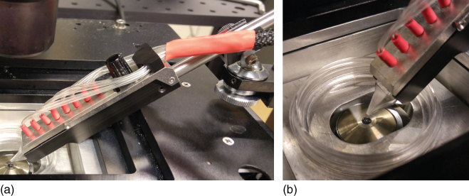
Figure 9.8 Experimental setup for operation of the pipette. (a) Typical arrangement of the pipette in an environment composed of an inverted fluorescence/confocal microscope with a motorized stage, a 50 mm cell culture dish, and the mechanical clamp situated on the ball joint of a Narishige micromanipulator. The holder is constructed like a crocodile clamp, with a thumb screw pressing the metal top and plastic bottom together. The top manifold piece, which holds the pressure lines connecting the wells to the vacuum and pressure pumps, also features barbs that seal the individual wells, which are supported by the elasticity of the PDMS material. (b) Magnified tip region, showing the working position of the tip directly above the center of the objective. This setup leaves sufficient space for at least two other probes to be used simultaneously, for example, a patch clamp needle, a microelectrode, or an optical fiber.
9.4.3 Operation
One of the most critical aspects of microfluidic devices is their acceptance by potential users. If microfluidic circuits and devices are cumbersome to connect, operate, and control, their innovative potential, for example, for enabling previously infeasible experimental procedures, will remain unused despite of obvious performance benefits. The holding manifold of the multifunctional pipette has been designed to render handling and application, predominantly in microscopy, clean and facile. The pneumatic actuation of the fluid flows makes contact between the reagent solution and any part of the instrument unnecessary. Solutions are pipetted into the wells, and the device is inserted into the holder, which is tightened and mounted onto the available micromanipulator. Due to the small amounts of reagents, which minimize the effects of inertia, and the rather hydrophobic nature of the pipette material, the solutions remain in the wells even under high angles of applications. Figure 9.8 shows an experimental setup that is typical for investigations in life science microscopy. Figure 9.8a is a photograph of the holding manifold, mounted via a ball joint to a manual micromanipulator. Since this particular setup uses a nanopositioning table, where the objective is positioned more than 5 cm below the top surface of the stage, the angle of operation exceeds 45°, which still is perfectly acceptable. In most cases, the application angle is not greater than ∼30°.
The mounting rod is fixed to the holder manifold with a set screw, which can be seen in Figure 9.8a. It allows for exchanging the rod according to the size of the mounting clamp on the micromanipulator and also enables special mounting options involving custom-made interfaces. Various commercial brands of manipulators with micrometer actuation capabilities exist. They are mechanically, water-/oil-hydraulically, or electrically driven and allow in most cases far more precise positioning than actually required to bring the pipette to the surface. The most important aspect is the availability of sufficiently fine movement in vertical direction, perpendicular to the sample plane. Under the microscope, the field of view is typically ∼100 µm or more across, and the pipette tip only needs to be somewhere in that range. In vertical direction, the precision of positioning should be on the order of less than 5 µm to avoid crashing the tip into the surface. Even if this occurs, it will not affect the pipette integrity or ability to operate, but it may disturb the objects on the cover slip, for example, detach or activate sensitive cells.
Figure 9.8b shows the tip region of the pipette in a typical application environment, deployed in a 50 mm cell culture dish and positioned directly above the microscope objective. The elongated format of the tip, the relatively small footprint, and the connection of the supply lines on the rear end of the pipette holder leave plenty of space for additional probes to be added to the setup. An optical fiber, a patch clamp pipette, a micro-thermocouple, and a carbon fiber microelectrode are examples of probes that are useful in the context of single-cell studies [14, 22, 26]. In the following application examples, some of these aspects are further illuminated.
9.5 Functional Extensions and Applications
As described above, the entire concept of a de facto consumable open volume device with facile fabrication, easily switchable solutions, pen-like shape format, and user-friendly loading, handling, deployment, and control is aimed at users that intend to carry out new types of life science experiments on adherent cells and require superfusion for that purpose. One important area of activity in biological cell research is the internalization of material to access the cellular machinery, deliver drugs, and transfect a cell with genetic material.
9.5.1 In-Channel Electrodes
The idea of supplementing the pipette with electroporation electrodes to enhance the rate of internalization by creating transient pores turned out to be rather challenging, as the deposition of metal films on PDMS is hampered by generally poor adhesion and the loss of conductivity due to the elasticity of the material, which easily leads to the formation of cracks in the thin metallic films. Techniques to deposit metal deeper into the surface of PDMS exist, but require unconventional fabrication technology [27]. Inserting solid-state electrodes, for example, in form of a wire, into the existing channels is only in rare cases a feasible solution. Several reports are available, in which PDMS was mixed with a conductive material, such as carbon nanotubes [28] or silver particles, to produce chip-embedded electrodes [29]. Direct injection of electrodes has also been shown, exploiting the low melting point of gallium [30] and some metallic alloys, such as gallium–indium eutectic [31] or tin-based solder [32]. Figure 9.9a shows an example of a functional extension of the multipipette by inserting Field's metal (a bismuth/indium/tin alloy, mp: 62 °C, conductivity s ∼ 2.56 S/m) as electrode material in one of the channels of a pipette [21]. This material is easily applied in a postproduction process, involving heating the device and pressure driving the molten metal through the channel, which only takes a few minutes. Electroporation of mammalian NG-108-15 cells, combined with delivery of several chemical compounds (calcium chloride and trypan blue for postdelivery viability testing), was achieved with this device and compares favorably with the alternative approach of co-deploying carbon fiber or metal wire microelectrodes with the pipette [21]. The channel layout is in this variant different from the standard design, as the metal application is evidently not compatible with a switching chamber. The holding manifold also needs to receive a modification in the form of a spring-loaded electrical contact to interface the metal-filled well on the device. On the application side, electrochemical corrosion erodes the surface of the electrode if pulses of positive polarity are applied through it. The electrode therefore needs to be gold plated prior to application. Field's metal is unfortunately also brittle, and cracks in the internalized electrode can occur over time if the pipette is accidentally twisted or bent.
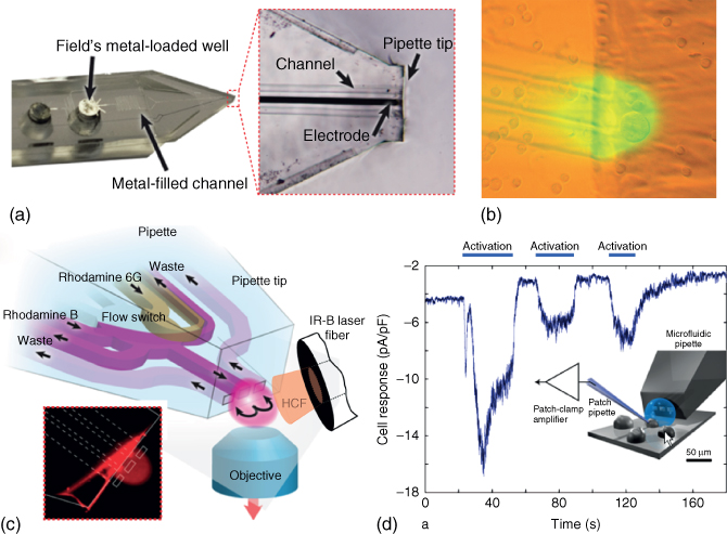
Figure 9.9 Example of areas of application of the multifunctional pipette. (a) For single-cell electroporation purposes, an in-channel electrode was fabricated, providing the ability to apply electrical pulses to the area immediately in front of the pipette tip. The center channel of the pipette was filled with a low melting temperature metal (Field's metal), which was injected into the channel from the connected well by means of pressure at elevated temperature. Subsequent cutting of the tip also shaped the end of the electrode (magnified region).
(Ainla et al. (2012) [21]. Copyright 2012. Reproduced with permission of American Chemical Society.) (b) Single-cell superfusion of mammalian cells from the CHO immortalized line. This mixed brightfield/fluorescence micrograph shows the position of the pipette in close vicinity to the surface, which is covered with mammalian cells from an immortalized cell line. Fluorescein solution is used to visualize the area covered by the recirculation volume (virtual flow cell). (c) Utilization of the multifunctional pipette as optofluidic temperature probe. An internal reference system comprising the two fluorescent dyes rhodamine B and rhodamine 6G, of which one shows strong and the other one negligible temperature dependence of the fluorescence intensity. The inset shows a confocal micrograph of the rhodamine 6G fluorescence. The pipette outlines are overlaid.
(Wegrzyn et al. (2013) [22]. Copyright 2013. Reproduced with permission of MDPI.) (d) Multiprobe configuration. The multifunctional pipette was used in support of patch clamp electrophysiology, which was applied in dose–response tests on TRPV1 ion channels overexpressed in Chinese hamster ovary (CHO) cells. The pipette exposed the selected and patched cell to a sequence of short pulse of acidic solution (pH 5.5), which caused a current response (∼−10 pA/pF) depicted in the graph against time. The experimental setup is also shown as a schematic drawing.
(Reprinted with permission from Ref. [14]. Copyright American Chemical Society 2010.)
Other chip modifications and extensions are expected to appear or have already appeared. So far, one example of a pipette variant with an integrated assay has been reported [33]. The application of the pipette as a sample collecting part of a µTAS is an exciting prospect for future development.
9.5.2 Single-Cell Superfusion
From the very beginning, the major focus of development of the pipette has been superfusion of single adherent cells and tissue samples with the aim of delivering drugs and other active compounds in low to medium throughput experiments. Nearly a dozen reports have been published, in which the pipette has been part of an experimental setup of one or another form of adherent single-cell manipulation. The original report in 2013, which introduced the concept of the pipette, already contained several different single-cell examples, including ion channel electrophysiology and induction of zeiosis (cell blebbing) on selected adherent cells [14]. Figure 9.9b shows in a mixed brightfield/fluorescence image an example of the application of the pipette to superfuse a selected group of Chinese hamster ovary (CHO) cells in an open volume containing a larger culture of the cells. The reach of the confined volume (virtual flow cell) is visualized by means of fluorescein solution being recirculating. Depending on the confluence of the culture, and the adjustment of the flow parameters, which influences the reach of the superfusion zone, single cells or small selected groups can be addressed. In the above mentioned case of induced zeiosis, the resulting blebs, or plasma membrane vesicles, are extraordinary shear sensitive. Surface-adhered giant phospholipid vesicles can normally not be treated with the pipette, since they are easily displaced from the surface by the shear forces of the hydrodynamic flow. A compromise between increased size (i.e., the number of affected cells) and low flow rate (i.e., decreased shear forces) allowed for applying the highly cytotoxic mixture of formaldehyde and DTT (dichlorodiphenyltrichloroethane) to a somewhat larger group but successively prevented the exposure of majority of the cells in the culture dish.
The fluid switching ability has shown to be highly beneficial in more complex experimental single-cell superfusion sequences. In one recent application example, chemical superfusion, delivery of substrate to cell-internal enzymes, intermediate washing steps, and subsequent viability testing have all been performed in a single experiment [34].
9.5.3 Optofluidic Thermometer
In most biological and biochemical experiments on living cells and tissue slices, control and measurement of local temperature are indispensable. Temperature adjustment in microscopy setups is typically achieved by means of heating stages, which affect the area around the specimen, or environmental chambers that envelope the entire microscope station. Although the control over the sample temperature achieved by these devices is precise and superbly stable, rapid temperature changes within seconds or even faster are not possible. For these purposes, local heating, for example, with an objective heating mantel or infrared laser, is required, which of course also involves the requirement of local temperature measurement. Solid-state probes embedded in the surface of the microscope sample slide, or microthermocouples, allow for local measurements [35], but indirect measurement of the temperature dependence of water viscosity (determination of the ion conductivity through small orifices) [36] and determination of the temperature-dependent change of fluorescence emission intensity of certain water soluble dyes [37–39] are even faster and operate in a contactless manner.
Utilizing the rapid solution switching capability of the pipette, two different rhodamine dyes with large differences in temperature dependency of their fluorescence intensity were sequentially recirculated (Figure 9.9c), and their response evaluated against a calibration curve for direct temperature measurement with an uncertainty of ±2.3 °C over a range between 15 and 60 °C [22]. Rhodamine B shows very strong rhodamine 6G-negligible fluorescence intensity dependence upon temperature. A comparative analysis has the benefit of excluding all environmental factors, such as pipette position, and microscope as well as detector settings. In addition, no special fabrication effort or auxiliary equipment is needed, and the typically rather troubling issues of fluorescent dye-based thermometers, such as absorption of the dye to the device walls, are avoided due to the virtual flow cell. The device needs calibration only once for a given pair of dyes (single wavelength ratiometric measurement) and concentration values. The calibration model is universally transferable, and absolute measurements can be performed directly on new samples without re-calibration. By means of finite element calculations, it was confirmed that rapid equilibration of temperature between the recirculating fluid in the confined volume and the surrounding volume occurs for flow rates less than 5 nL/s.
The optofluidic thermometer can be freely moved to any point in the open volume and allows for contactless temperature measurement close to the surface and in the vicinity of single cells. The currently somewhat limited precision can very likely be enhanced, together with other figures of merit, such as dynamic range, spatial resolution, and sensitivity. Different sets of dyes, a smaller recirculation zone, and fluorescent nanoparticles instead of dye molecules might offer improvements in this direction.
9.5.4 Multiprobe Operation
Figure 9.8b shows clearly that the free space around the pipette is large enough to accommodate additional probes, electrodes, or other microinstruments required in certain complex experimental arrangements. The proof of concept of the optofluidic temperature probe (Figure 9.9c) was obtained by means of local heating with an optical fiber that channeled 1470 nm IR-B light directly to the cell. In addition, a micro-thermocouple was simultaneously manipulated into the setup in order to record the calibration curve. The co-location of three probes posed no particular problems, although coordinated adjustment by means of the micromanipulators requires a certain degree of familiarity with the equipment in order to avoid collisions between the different components.
Another example of co-located probes in an ion channel study-related microscopy experiment on mammalian cells is displayed in Figure 9.9d [14]. Various microfluidic approaches have succeeded in reducing the exposure of non-clamped cells in a culture to the activating compound, but could not entirely eliminate the problem. The multifunctional pipette has remedied this situation. The panel displays schematically the setup, and a graph of response versus time data from a single-cell patch clamp recording of the TRPV1 ion channel (nociceptor channel present in trigeminal and dorsal root sensory ganglia), overexpressed in mammalian cells. The electrical current recording shows the response of the voltage-clamped cell to rapid changes of the pH value from 7.8 to 5.5 in the recirculated solution, which activates the ion channels in the exposed cells. Low pH is one of the exogenous TRPV1 channel activators, besides heat and capsaicin. Repeated stimulation leads to desensitization of the cell, which is represented by the decrease in current response over time.
9.5.5 Lab-on-a-Membrane
The “laboratory on a molecularly thin membrane” [40] is another, rather unique, application of the multifunctional pipette, which focuses on precision writing and postwriting modification of artificial biomembranes on a variety of surfaces. This direct writing approach, in which lipid nanoparticles are transformed into surface-supported phospholipid films, is essentially a 3D printing application with molecular resolution in one dimension and micrometer resolution in the other two. It can be considered as a rapid prototyping technology for the on-demand generation of biomimetic membranes.
Figure 9.10 shows the principle of the lab-on-a-membrane: if the multifunctional pipette, loaded with a suspension of phospholipid vesicles (i.e., liposomes – hollow shell lipid nanoparticles) is positioned close to a surface, such as glass, and the suspension is recirculated, the vesicles interact with the surface. Instead of aspirating the entire injected material back into the device, which is the goal of nearly all superfusion applications, some of the vesicles remain adhered to the surface. The lipid particles, in this case small unilamellar vesicles of a particular composition with a diameter in the range between 20 and 100 nm, not only are adsorbed but also undergo transformation from individual particles into a continuous biomimetic membrane and a membrane patch forms on the surface within 10–30 s (Figure 9.10a, left panel). Depending on the energy of the surface, either monolayers (polymer surfaces) or bilayers (glass, oxides, nitrides) are deposited.

Figure 9.10 Laboratory-on-a-membrane. (a) Direct writing and subsequent modification of molecular phospholipid films on solid substrates. (b) The switching capability of the pipette allows for writing of four different “pure” membrane types and mixtures thereof, onto predetermined areas of the surface. (c) The mechanism of film formation on high energy surfaces such as glass or silicon dioxide is a vesicle adhesion-rupture sequence that forms fluid bilayer phospholipid membranes. (d) Confocal micrographs of two prototype phospholipid bilayers of different composition, written by means of the pipette on glass substrates. Each lipid type contains 1% of fluorescently labels lipids for visualization. The formation time of each film is on the order of several minutes.
The pipette, having the capacity for additional contents, can in a subsequent step perform a chemical or physical modification of the membrane patch (Figure 9.10a, right panel). Chemical or biochemical operations could include the decoration of the membrane patch with antibodies against membrane constituents, or chemical transformations of the lipid molecules, for example, head group modifications or polymerization. Physical transformations are also very interesting; examples include the fusing of vesicles of different lipid composition with the membrane in the deposited patch or the erasing of lipid patches by means of a recirculating detergent.
If the pipette is translated in between depositions, and at the same time the recirculating vesicle suspension is changed, arrays of lipid patches of different contents can be written in rapid succession (Figure 9.10b). This has previously been possible only in a limited manner inside microfluidic channels or by means of lipid transfer from modified AFM (atomic force microscopy)-cantilevers to a flat surface [41]. Formally, four different compositions are possible with the current device, but in sequential application of pulses from different channels in the manner of pulse width flow modulation [42], mixed patches can be produced.
The currently accepted mechanism of lipid bilayer membrane generation from small unilamellar vesicles on solid surfaces is depicted in Figure 9.10c [43, 44]. Vesicles readily adhere to the surface due to the high surface energy. They deform and eventually rupture, which gradually increases the contact area between lipid film and surface. Since wetting of the surface is favored in order to lower its energy, the process continues until the vesicle is fully transformed and the entire surface area wetted by the membrane. Once a membrane is formed, but remains in the hydrodynamically confined volume, it continues to interact with the vesicles. Depending on the lipid composition of the vesicles, they can either fuse with the membrane or be repelled. In the former case, the patch can grow in size by radial spreading as long as the supply of vesicles through the HCF continues. In the latter scenario, vesicles adhere, rupture, and interconnect to a continuous membrane only as long as free surface area is available. Once the membrane is formed, it remains unchanged, and the size of the patch does not exceed the footprint of the recirculation volume.
If the pipette or surface, for example, fixed on a microscope stage, is translated at a linear velocity of 1–5 µm/s, while at the same time delivering vesicle suspension, continuous lipid membrane circuits can be written (Figure 9.10d). Here, compositional variations are also possible in a number of ways. The top image shows a binary composition, written as two overlapping crosses, employing vesicles composed of fusible lipids and individual fluorescent labels for visualization. The structure shown in the figure is already in the process of diffusive mixing. The produced phospholipid films are continuous, and they display 2D fluidity, meaning that compositional differences between different areas of a connected film will eventually equilibrate by diffusion, leading to a homogenous composition. The bottom picture shows a structure written from a single lipid composition, which was also fluorescently labeled.
The lab-on-a-membrane provides essentially a prototyping toolbox for biomembrane generation, which is very flexible in terms of lipid film composition, sequences of membrane manipulation, size and location of deposition areas on a surface, chemical and physical modification schemes, and so on. The original publication in 2013 contains a multitude of examples, including a hydrodynamic trap, localized binding of antibodies, and directed membrane transport on a microstructured surface, further ready-to-apply protocols, tables of suitable lipid compositions, and experimental sequences [40]. Most experiments were performed on float glass slides, but a variety of other surfaces is suitable, including silicon and aluminum oxide, silicon nitride and carbide, quartz, and even graphene. On these “high surface energy” substrates, double or bilayers are formed. Films can also be written on many polymer surfaces, including acrylates, epoxy polymers, and Teflon, on which lipid monolayers are readily formed.
The concept has proven to be robust and practical. It significantly facilitates the deployment of supported phospholipid films and biomembranes, making them accessible to a broader range of applications and fundamental studies. Liposomes prepared from biological cell fractions allow the incorporation of membrane proteins. In this context, network writing, erasing, and reconnection sequences are particularly interesting, since they provide the opportunity to initiate, control, and study the migration and functions of membrane-associated species in a time-saving and sample-preserving manner. The design of the networks is ultimately software defined with respect to assembling membrane constituents and reactants and to substrate positioning and timing. Any fluorescence microscopy setup, preferentially with a motor-driven stage, is sufficient to support lab on a membrane experiments.
9.6 Future Technology
The multifunctional pipette shows promise to become a routine tool in life science research areas where single-cell and tissue cultures are probed. The development of the pipette has led to a reliable, user-friendly turn-key instrument. However, a number of future improvements and design changes can already be anticipated. Some of them concern issues of automation and improvements in pipette fabrication, and others aim at extended functionality and on-chip features. For example, larger pipette bodies with more solutions and larger waste collection wells will allow for longer superfusion experiments with more complex solution exchange sequences, which are a relatively simple development issue that only require redesign of holding manifold and an update of controller features and software. Changes in material, embedding of on-chip sensors, and other functionalities require more experimental work.
9.6.1 Materials and Fabrication
The soft lithography and the membrane fabrication process are still belonging to the category of prototyping technologies, with limited output and long processing times. Moreover, the previously mentioned integration of on-chip electrodes remains difficult as long as PDMS is used for fabrication. There are a number of other materials that might be considered for the next-generation pipette. The choice of elastic PDMS as material for pipette fabrication has had a large influence on the success of the pen-like device. The resulting flexibility of the pipette tip and the ability to fabricate the 10 µm thin membrane by spin coating from fluid prepolymer are distinct benefits. However, disadvantages such as the requirement for tip cutting and the still relatively bulky tip led to searches for other fabrication routes and materials. Clean-room compatible materials such as the epoxy photoresist SU-8, a superb hard polymer material, would solve these issues entirely, but there are no well-established multilayer processes for these materials. A fabrication processes for a single channel layer in SU-8 requires spin coating of top and bottom layers, where one of them contains the channel walls, subsequent pressure bonding at elevated temperature, and releases from the substrate. The fabrication and bonding can be conveniently achieved with exposed and developed, but not hardbaked resist, but the lift-off from the wafer substrate requires a release layer, for which suitable materials are surprisingly hard to find. However, the integration of metal films as electrode, either embedded in the channel walls or along the channel structures, poses no difficulties. Figure 9.11 shows a photograph of a research prototype of a pipette tip, fabricated from SU-8, which has three parallel microelectrodes with 10 × 10 µm surface area embedded above the channel openings. It was produced through an experimental two-layer lithography/bonding process using thermal release tape as lift-off layer and used to evaluate the projected benefits over the PDMS process, as well as to get a first idea about performance and interfacing options of the resulting device.
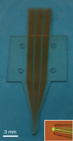
Figure 9.11 Advanced hard polymer version of the multifunctional pipette with integrated gold microelectrodes. This photograph shows the second generation of the multifunctional pipette, fabricated by a multilayer process from the epoxy polymer SU-8. The inset is an overlaid brightfield/fluorescence micrograph of the pipette tip (electrode-less version), recirculating fluorescein solution.
The device has a very small tip geometry, compared with the PDMS pipette (Table 9.1). The entire tip size can in theory exceed the channel dimensions only by a single-wall layer of 25 µm laterally. In practice, a somewhat broader base is required but solely for the purpose of releasing the pipettes from the fabrication wafer without damaging the delicate tip. The small footprint eliminates the casting of shadows during deployment under the microscope completely (Figure 9.11, inset), which facilitates the positioning tremendously. Furthermore, the device is inelastic and has therefore no compliance. However, a number of drawbacks need to be addressed in further research. Interfacing to a pipette body with wells is required. Port holes of Ø 0.5–1 mm, clearly visible in the figure, make alignment uncomplicated, and there are several options for pipette body materials. The use of PDMS could be continued, although only a very limited number of adhesives are effective on silicone rubber. Alternatively, a great variety of other plastic materials are available. Injection molding to form the body would be fairly straightforward, since the microchannels, including flow switching chamber, only need to be present in the epoxy tip. Interfacing by adhesive tape would in this case also be uncomplicated. This line of development clearly has merits and can generate a large number of tips per batch, provided that a robust photolithographic fabrication process can be eventually established. Alternatively, thermoplastic elastomers and a number of new engineering materials, such as off-stoichiometry thiol elastomer (OSTE) materials, are available. For these material options, however, the fabrication of the thin bottom membrane poses a considerable challenge.
Finally, another issue of amplified photoresists, to which the aromatic SU-8 and its aliphatic analogue, EPON, belong, has to be mentioned. The photoacid required to cross-link the epoxy polymers irreversibly to a solid exhibits autofluorescence, which considerably limits the use of the hard-polymer tips currently in single-cell studies. Remedies might possibly be found in blending the resist with a quencher or coating the pipette with an intransparent material. A reliable method to address this problem still remains to be found. In general, alternative materials represent a valid option to scale up the fabrication of tips and introduce at the same time performance improvements. The possibility to embed electrodes is certainly also very interesting, for example, to provide the option of electroporation or enable impedance spectroscopy during superfusion, but by no means the only way to add additional functionality.
9.6.2 Collection and Integration of Assays and Sensors
So far, the pipette has been exclusively used to recirculate chemical compounds and biochemical agents, mostly in cell and tissue superfusion experiments. An interesting additional feature would be, however, the ability to collect material released by the cell in response to the applied stimulus. Examples include small peptides, extracellular vesicles, and other lipid particles, enzymes, or genetic material. Analysis of the released material could expand the capabilities of single-cell research tremendously. The collection of cell material would immediately open an entire new research field.
Unfortunately, the principle of hydrodynamic flow requires that a certain amount of open bath solution is aspirated in addition to the contents of the recirculation volume (Figure 9.1). We estimated that the dilution of chemical material released by a cell within the virtual flow cell lies initially in the range between 20- and 100-fold. The situation will even get worse over time, since the recirculation waste wells are continuously being filled as long as the pipette is in operation. This could be improved by establishing a new design, which allows opening pathways to additional collection wells. Physical blocking of the channels will be required, since flow switches following the principle of the microfluidic fraction collector (Figure 9.6) require a constant flow, which aggravates the situation. Quake valves are one way of embedding such valves, which would require quite extensive design changes, as an additional control channel layer is needed in the chip design, as well as additional control pressure lines in the mounting interface, and upgrades in controller hardware and software. In any case, the collection of cellular release is a very prospective direction of further research and development, which would in extension also involve the implementation of sensors, for example, mass-sensitive surface acoustic wave elements, amperometric or potentiometric sensors, or optical sensors, in the area beneath the collection wells. Such ambitions are still way ahead, but seem clearly possible in the context of µTAS customized for single-cell investigations.
It has been recently shown that the integration of the three-channel recirculation concept with an on-chip assay creates opportunities in diagnostics [33]. Here the entire targeted cell was lysed inside the recirculation volume by means of an enzymatic digestion protocol, and the breakdown products were collected and analyzed on chip. This chip involved air-pneumatic valves of the Quake type and received its reagent supplies through tubing driven by syringe pumps. It represents an encouraging first step in the direction toward a single-cell µTAS and is expected to be followed by similar applications shortly. The continuous improvement of the figures of merit of microfabricated sensors and the fast-paced development of new sensing elements will certainly create ample opportunities for expanding the capabilities of the multifunctional pipette in the near future.
9.6.3 Automation
The multifunctional pipette is a medium throughput device that is in its current state of development in no reasonable way capable of high throughput superfusion. Although complicated sequences of solution exchange operations, pulsing, and washing steps can be performed autonomously with the help of the control software, the preparations for operation and positioning are still manual. Some hands-on experience is currently indispensable in order to position the pipette correctly with respect to the surface. A high degree of automation of single-cell experiments with a significant increase in throughput is in principle possible, if aspects such as automated tracking of the device tip, identification of suitable cells, and automated positioning are considered. This would require a deeper integration of the pipette controller with the microscope hardware, cameras, manipulators, and stage controllers. All of the hardware, as well as associated software libraries and drivers, exist in principle, but the many different types of microscopes and peripheral devices make a universal solution, which is of course highly desirable, very difficult. The most significant improvement in user-friendliness could be achieved through an automated protocol for correctly positioning the tip at the proper distance from the surface. Moreover, tracking of reagent consumption and detection of the fluid level in the vacuum (collection) wells are also high on the list of desirable features.
A higher degree of automation should also be of advantage in the fabrication of the pipette devices. Automatic sequences for continuous injection of prepolymer mixture, release from the master, punching, bonding, and cutting should be possible, and even the fabrication of the membrane should be possible to integrate into such an environment. The ongoing search for alternative elastomeric or hard polymer materials, which are supported by more conventional processing strategies, has so far prevented serious efforts in this direction. Semiautomatic steps, facilitating cutting and shaping of the pipette, are currently under investigation.
In summary, the multifunctional pipette has demonstrated its utility in various application contexts, leaving ample opportunity for extension, improvement, and integration with common research environments. The design idea of combining of the benefits of glass needles and microfluidic circuitry, while at the same time eradicating some of the drawbacks that hampered the application of open volume devices to adherent cells, was implemented with promising results. The direction of highest future technology potential is the possibility to collect and analyze the inflow in the device. This certainly goes hand in hand with on-chip sensor integration, more versatile flow switching, and, possibly, facile interfacing to very sensitive external analytical instrumentation. It is clear that the multifunctional pipette will benefit from the generally expected rapid progress in the development if miniaturized communication and data transfer technology, standardized and more abundant microfluidic and micromanipulation components and fabrication technologies, and engineering and manufacturing advances such as affordable 3D printing, which help building chip-interfaced and peripheral components. The pipette development has so far been a challenging, highly interesting transdisciplinary endeavor and will continue to be one for years to come.
Acknowledgments
Numerous people contributed to the success of the multifunctional pipette. The authors are grateful to all of them for their support, their spirit of discovery that made many improvements and applications possible, and their expertise in particular aspects of each project. Incredibly influential were Alar Ainla and Gavin Jeffries, who did most of the development and were involved in nearly all application trials. Also, thanks to current and former interns, students, and postdocs at the Biophysical Technology Laboratory at Chalmers, who enabled and performed all the life science applications: Anna Kim, Kiryl Kustanovich, Shijun Xu, Mehrnaz Shaali, Aikeremu Ahemaiti, Venkata Anil Kumar Modali, Davood Baratian, Ilona Wegrzyn, Bodil Hakonen, Erik Jansson, Haijiang Zhang, Natalia Stepanyants, Alessia Donati, Nicolas Sanchez, Farhan Hasan, and Ralf Brune. We are deeply grateful to our collaborators: foremost Professors Holger Wigström, Kent Jardemark, Joseph Bruton, Ilya Reviakine, and Håkan Westerblad. The authors also thank the team of Fluicell AB for their tireless effort to make the pipette available to life scientists worldwide and the staff of the clean room facility MC2 at Chalmers for their help and advice with fabrication technology.
References
- 1 Strutt, J.W.L.R. (1878) On the instability of jets. Proc. Lond. Math. Soc., 10, 4–13.
- 2 Weigl, B.H., Bardell, R.L., and Cabrera, C.R. (2003) Lab-on-a-chip for drug development. Adv. Drug Delivery Rev., 55, 349–377.
- 3 Karniadakis, G., Beskok, A., and Aluru, N. (2005) Microflows and Nanoflows: Fundamentals and Simulation, Springer, New York.
- 4 Gervais, L., de Rooij, N., and Delamarche, E. (2011) Microfluidic chips for point-of-care immunodiagnostics. Adv. Mater., 23, H151–H176.
- 5 Shembekar, N., Chaipan, C., Utharala, R., and Merten, C.A. (2016) Droplet-based microfluidics in drug discovery, transcriptomics and high-throughput molecular genetics. Lab Chip, 16, 1314–1331.
- 6 Fodor, L. and Tarnawa, I. (2009) Application of automated patch clamp in ion channel pharmacology research: Dynaflow and QPatch systems. Acta Physiol. Hung., 96, 75.
- 7 Pidoplichko, V.I. and Dani, J.A. (2005) Applying small quantities of multiple compounds to defined locations of in vitro brain slices. J. Neurosci. Methods, 142, 55–66.
- 8 Feinerman, O. and Moses, E. (2003) A picoliter “fountain-pen” using co-axial dual pipettes. J. Neurosci. Methods, 127, 75–84.
- 9 Juncker, D., Schmid, H., and Delamarche, E. (2005) Multipurpose microfluidic probe. Nat. Mater., 4, 622–628.
- 10 Christ, K.V. and Turner, K.T. (2011) Design of hydrodynamically confined microfluidics: controlling flow envelope and pressure. Lab Chip, 11, 1491–1501.
- 11 Kaigala, G.V., Lovchik, R.D., Drechsler, U., and Delamarche, E. (2011) A vertical microfluidic probe. Langmuir, 27, 5686–5693.
- 12 Lovchik, R.D., Drechsler, U., and Delamarche, E. (2009) Multilayered microfluidic probe heads. J. Micromech. Microeng., 19, 8.
- 13 Queval, A. et al. (2010) Chamber and microfluidic probe for microperfusion of organotypic brain slices. Lab Chip, 10, 326–334.
- 14 Ainla, A., Jansson, E.T., Stepanyants, N., Orwar, O., and Jesorka, A. (2010) A microfluidic pipette for single-cell pharmacology. Anal. Chem., 82, 4529–4536.
- 15 Ainla, A., Jeffries, G.D.M., Brune, R., Orwar, O., and Jesorka, A. (2012) A multifunctional pipette. Lab Chip, 12, 1255–1261.
- 16 Olofsson, J. et al. (2004) A microfluidics approach to the problem of creating separate solution environments accessible from macroscopic volumes. Anal. Chem., 76, 4968–4976.
- 17 Fodor, L. and Tarnawa, I. (2008) Studying ion channel pharmacology using the Dynaflow patch clamp system. Fundam. Clin. Pharmacol., 22, 68.
- 18 Autebert, J., Kashyap, A., Lovchik, R.D., Delamarche, E., and Kaigala, G.V. (2014) Hierarchical hydrodynamic flow confinement: efficient use and retrieval of chemicals for microscale chemistry on surfaces. Langmuir, 30, 3640–3645.
- 19 Bruton, J., Jeffries, G.D.M., and Westerblad, H. (2014) Usage of a localised microflow device to show that mitochondrial networks are not extensive in skeletal muscle fibres. PLoS One, 9, e108601.
- 20 Baker, C.A. and Roper, M.G. (2010) A continuous-flow, microfluidic fraction collection device. J. Chromatogr. A, 1217, 4743–4748.
- 21 Ainla, A., Xu, S., Sanchez, N., Jeffries, G.D.M., and Jesorka, A. (2012) Single-cell electroporation using a multifunctional pipette. Lab Chip, 12, 4605–4609.
- 22 Wegrzyn, I., Ainla, A., Jeffries, G.D.M., and Jesorka, A. (2013) An optofluidic temperature probe. Sensors, 13, 4289–4302.
- 23 Xia, Y.N. and Whitesides, G.M. (1998) Soft lithography. Angew. Chem. Int. Ed., 37, 550–575.
- 24 Xia, Y.N. and Whitesides, G.M. (1998) Soft lithography. Annu. Rev. Mater. Sci., 28, 153–184.
- 25 Haubert, K., Drier, T., and Beebe, D. (2006) PDMS bonding by means of a portable, low-cost corona system. Lab Chip, 6, 1548–1549.
- 26 Xu, S.J., Ainla, A., Jardemark, K., Jesorka, A., and Jeffries, G.D.M. (2015) A heating-superfusion platform technology for the investigation of protein function in single cells. Anal. Chem., 87, 381–387.
- 27 Choi, J.W. et al. (2010) 3-dimensional electrode patterning within a microfluidic channel using metal ion implantation. Lab Chip, 10, 783–788.
- 28 Pavesi, A. et al. (2011) How to embed three-dimensional flexible electrodes in microfluidic devices for cell culture applications. Lab Chip, 11, 1593–1595.
- 29 Lewpiriyawong, N., Yang, C., and Lam, Y.C. (2010) Continuous sorting and separation of microparticles by size using AC dielectrophoresis in a PDMS microfluidic device with 3-D conducting PDMS composite electrodes. Electrophoresis, 31, 2622–2631.
- 30 Priest, C. et al. (2011) Microplasma patterning of bonded microchannels using high-precision “injected” electrodes. Lab Chip, 11, 541–544.
- 31 So, J.-H. and Dickey, M.D. (2011) Inherently aligned microfluidic electrodes composed of liquid metal. Lab Chip, 11, 905–911.
- 32 Siegel, A.C. et al. (2006) Cofabrication of electromagnets and microfluidic systems in poly(dimethylsiloxane). Angew. Chem. Int. Ed., 45, 6877–6882.
- 33 Sarkar, A., Kolitz, S., Lauffenburger, D.A., and Han, J. (2014) Microfluidic probe for single-cell analysis in adherent tissue culture. Nat. Commun., 5, 3421.
- 34 Xu, S.J., Kim, A., Jeffries, G.D.M., and Jesorka, A. (2015) A rapid microfluidic technique for integrated viability determination of adherent single cells. Anal. Bioanal. Chem., 407, 1295–1301.
- 35 Childs, P.R.N., Greenwood, J.R., and Long, C.A. (2000) Review of temperature measurement. Rev. Sci. Instrum., 71, 2959–2978.
- 36 Yao, J., Liu, B., and Qin, F. (2009) Rapid temperature jump by infrared diode laser irradiation for patch-clamp studies. Biophys. J., 96, 3611–3619.
- 37 Ross, D., Gaitan, M., and Locascio, L.E. (2001) Temperature measurement in microfluidic systems using a temperature-dependent fluorescent dye. Anal. Chem., 73, 4117–4123.
- 38 Ross, D. and Locascio, L.E. (2003) Fluorescence thermometry in microfluidics, in Temperature: Its Measurement and Control in Science and Industry, Vol 7, Pts 1 and 2, vol. 684, American Institute of Physics, Melville, pp. 1051–1055.
- 39 Zeeb, V., Suzuki, M., and Ishiwata, S. (2004) A novel method of thermal activation and temperature measurement in the microscopic region around single living cells. J. Neurosci. Methods, 139, 69–77.
- 40 Ainla, A., Gozen, I., Hakonen, B., and Jesorka, A. (2014) Lab on a biomembrane. Biophys. J., 106, 209A.
- 41 Hirtz, M., Oikonomou, A., Georgiou, T., Fuchs, H., and Vijayaraghavan, A. (2013) Multiplexed biomimetic lipid membranes on graphene by dip-pen nanolithography. Nat. Commun., 4. Article number 2591, doi:10.1038/ncomms3591
- 42 Ainla, A., Gozen, I., Orwar, O., and Jesorka, A. (2009) A microfluidic diluter based on pulse width flow modulation. Anal. Chem., 81, 5549–5556.
- 43 Keller, C.A., Glasmastar, K., Zhdanov, V.P., and Kasemo, B. (2000) Formation of supported membranes from vesicles. Phys. Rev. Lett., 84, 5443–5446.
- 44 Reimhult, E., Hook, F., and Kasemo, B. (2003) Intact vesicle adsorption and supported biomembrane formation from vesicles in solution: influence of surface chemistry, vesicle size, temperature, and osmotic pressure. Langmuir, 19, 1681–1691.