
1
Visual Cryptography from Halftone Error Diffusion
Gonzalo R. Arce
University of Delaware, USA
Zhongmin Wang
University of Delaware, USA
Giovanni Di Crescenzo
Telcordia Technologies Inc., USA
CONTENTS
1.1 Introduction
Visual cryptography (VC), proposed by Naor and Shamir in [19], is a paradigm for cryptographic schemes that allows the decoding of concealed images without any cryptographic computation. Particularly in a k-out-of-n visual secret sharing scheme (VSS), a secret image is cryptographically encoded into n shares. Each share resembles a random binary pattern. The n shares are then xeroxed onto transparencies respectively and distributed among n participants. The secret images can be visually revealed by stacking together any k or more transparencies of the shares and no cryptographic computation is needed. However, by inspecting less than k shares, one cannot gain any information about the secret image, even if infinite computational power is available. Aside from the obvious applications to information hiding, VC can be applied to access control, copyright protection [10], watermarking [8], visual authentication, and identification [18].
1.1.1 Visual Cryptography
The main instantiation of VC realizes a cryptography protocol called secret sharing (SS). In a conventional SS scheme, a secret image is shared among n participants in such a way that subsets of qualified participants can pull their shares and recover the secret but subsets of forbidden participants can obtain no information about it. Here, both the sharing phase and the reconstruction phase involve algorithms that are run by computers (specially, a dealer runs a distribution algorithm and a set of qualified parties can run a reconstruction algorithm). The surprising novelties of a VSS scheme are in representing data as images and in an elementary realization of the reconstruction phase, consisting of just viewing the image obtained after stacking transparencies. VSS schemes inherit all applications of conventional SS schemes; most notably, access control. As an example, consider a bank vault that must be opened everyday by five tellers, but for security purposes it is desirable not to entrust any two individuals with the combination. Hence, a vault-access system that requires any three of the five tellers may be desirable. This problem can be solved using a 3-out-of-5 threshold scheme. In addition to access control, VSS schemes can be applied to a number of other cryptographic protocols and applications using conventional SS, such as threshold signatures, private multiparty function evaluation, electronic cash, and digital elections.
Another quite intriguing instantiation of VC schemes realizes VSS with innocent-looking images as shares. This version of VSS has applications to a multiparty variant of steganography. In a steganography scheme, a user A sends an innocent-looking image to another user B, in such a way that B can recover some hidden images, but no observer of the communication between A and B even suspects that the communication contains some hidden images. In a multiparty variant of conventional steganography schemes, a user A sends innocent-looking images to users, B1, …, Bm in such a way that qualified subsets of the recipients can recover some hidden image, but no observer of the communication between A and B1, …, Bm even suspects the existence of hidden images. Interestingly, a version of VSS with innocent-looking images as shares can implement this steganography variant. In practice, however, both regular VSS and VSS with innocent-looking images work by expanding a single pixel of an image into multiple pixels, with consequences on image quality. It is indeed of great interest to design schemes achieving high image quality. Although the literature has paid a significant amount of attention to VSS, some different paradigms of VC have also been studied, giving rise to visual versions of other types of cryptographic protocols.
1.1.2 Halftone Visual Cryptography
Traditional VC constructions are exclusively based on combinational techniques. In the halftoning framework of VC, a secret binary image is encrypted into high-quality halftone images, or halftone shares. In particular, this method applies the rich theory of blue noise halftoning to the construction mechanism used in conventional VSS schemes to generate halftone shares, while the security properties are still maintained. The decoded secret image has uniform contrast. The halftone shares carry significant visual information to the reviewers, such as landscapes, buildings, etc. The visual quality obtained by the new method is significantly better than that attained by any available VSS method known to date. As a result, adversaries, inspecting a halftone share, are less likely to suspect that cryptographic information is hidden. A higher security level is thus achieved [26, 23].
1.1.3 Blue Noise Error Diffusion
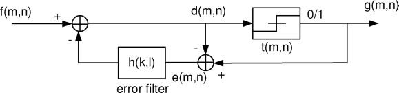
FIGURE 1.1
Block diagram for binary error diffusion. The pixel f(m, n) is passed through a quantizer to obtain the corresponding pixel of the halftone g(m, n). The difference between these two pixels is diffused to the neighboring pixels by means of the filter h(k, l). (Reprinted with permission from IEEE Trans. Inf. Forensics Security, vol. 4, no. 3, pp. 383–396, Sep. 2009 ©IEEE 2009)
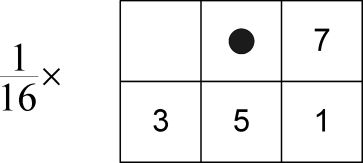
FIGURE 4.1
Floyd-Steinberg error filter. • indicates the current pixel. The weights are given by: h(0, 1) = 7/16, h(1, −1) = 3/16, h(1,0) = 5/16 and h(1,1) = 1/16. (Reprinted with permission from IEEE Trans. Inf. Forensics Security, vol. 4, no. 3, pp. 383–396, Sep. 2009 © IEEE 2009).
Among all blue noise halftoning algorithms, error diffusion is a simple, yet efficient algorithm to halftone a grayscale image. The quantization error at each pixel is filtered and fed back to a set of future input samples. Figure 1.1 shows a binary error diffusion diagram where f(m, n) represents the (m, n)th pixel of the input grayscale image, d(m, n) is the sum of the input pixel value and the “diffused” past errors, and g(m, n) is the output quantized pixel value [12, 16]. Error diffusion consists of two main components. The first component is the thresholding block where the output g(m, n) is given by:
The threshold t(m, n) can be position-dependent. The second component is the error filter h(k, l) whose input e(m, n) is the difference between d(m, n) and g(m, n). Finally, we can compute d(m, n) as:
As an example, the widely used Floyd-Steinberg error filter is shown in Figure 1.2 where • indicates the current pixel. The weights of the filter are given by: h(0,1) = 7/16, h(1, −1) = 3/16, h(1, 0) = 5/16 and h(1, 1) = 1/16.
The recursive structure of the block diagram shown in Figure 1.1 indicates that the quantization error e(m, n) depends not only on the current input and output but also on the entire past history. The error filter is designed in such a way that the low frequency difference between the input and output image is minimized. The error that is diffused away by the error filter is high frequency or “blue noise” in nature, leading to visually pleasing halftone images for human vision [12, 13, 7]. As will be described in this chapter, all the shares in the introduced halftone visual cryptography (HVC) methods are generated by a constrained error diffusion based on the algorithm introduced above.
For the HVC construction methods to be introduced shortly, it is necessary to generate mutually exclusive sets of pixels. To this end, the method of error diffusion is modified so as to produce multitone output pixels where the pixels of each tone are assigned to a pixel set. Multitone error diffusion is obtained by simply replacing the thresholding block by a multilevel quantization block in halftone error diffusion. The number of output levels of the quantization block is the same as the number of tones of the multitone image [15]. Multitone error diffusion can generate multitone images where the pixels of each tone are homogeneously distributed. The multitone error diffusion algorithm proposed in [4] is used here for the generation of mutually exclusive pixel sets. This algorithm jointly optimizes the distribution of multitone pixels by locating the pixels of different tones in a correlated fashion so that the mutual interference between different tones is minimized and multitone pixels are well separated from each other. Refer to [4] for details.
1.2 Visual Secret Sharing
We provide a brief description on visual cryptography where the key concepts will be referenced in subsequent sections. Please refer to [19, 2] for more details on VSS.
1.2.1 Notion and Formal Definitions
To illustrate the principles of VSS, consider a simple 2-out-of-2 VSS scheme shown in Figure 1.3. Each pixel p taken from a secret binary image is encoded into a pair of black and white subpixels in each of the two shares. If p is white/black, one of the first/last two columns tabulated under the white/black pixel in Figure 1.3 is selected. The selection is random such that each column is selected with a 50% probability. Then, the first two subpixels in that column are assigned to share 1 and the following two subpixels are assigned to share 2. Independent of whether p is black or white, p is encoded into two subpixels of black-white or white-black with equal probabilities. Thus, an individual share gives no clue as to whether p is black or white [26, 25]. Now consider the superposition of the two shares as shown in the last row of Figure 1.3. If the pixel p is black, the superposition of the two shares outputs two black subpixels corresponding to a gray level 1. If p is white, it results in one white and one black subpixel, corresponding to a gray level 1/2. Then by stacking two shares together, we can obtain the full information of the secret image.
Figure 3.24 shows an example of the application of the 2-out-of-2 VSS scheme. Figure 1.4(a) shows a secret binary image SI to be encoded. According to the encoding rule shown in Figure 1.3, each pixel p of SI is split into two subpixels in each of the two shares, as shown in Figure 1.4(b) and Figure 1.4(c). Superimposing the two shares leads to the output secret image shown in Figure 1.4(d). The decoded image is clearly identified, although some contrast loss occurs. The width of the reconstructed image is twice that of the original secret image since each pixel is expanded to two subpixels in each share.

FIGURE 1.3
In a 2-out-of-2 scheme, a secret pixel is encoded into 2 subpixels in each of the two shares. (Reprinted with permission from IEEE Trans. Inf. Forensics Security, vol. 4, no. 3, pp. 383–396, Sep. 2009 ©IEEE 2009).
The 2-out-of-2 VSS scheme demonstrated above is a special case of the k-out-of-n VSS scheme [19]. Ateniese et al. designed a more general model for VSS schemes based on general access structures [2]. An access structure is a specification of all the qualified and forbidden subsets of shares. The participants in a qualified subset can recover the secret image while the participants in a forbidden subset cannot. Formal definitions of VSS are presented below.
Let P = {1, · · · , n} be a set of elements called participants. A visual secret sharing scheme for a set P of n participants is a method to encode a secret binary image SI into n shadow images called shares, where each participant in P receives one share. Let 2P denote the set of all subsets of P and let ΓQual ⊆ 2P and ΓForb ⊆ 2P, where ΓQuaι ∩ ΓForb = ∅. We refer to members of ΓQual as qualified sets and call members of ΓForb forbidden sets. The pair (ΓQual, ΓForb) is called the access structure of the scheme [2].
Any qualified set of participants X ∈ ΓQual can visually decode SI, but a forbidden set of participants Y ∈ ΓForb has no information of SI [2, 3]. A visual recovery for a set X ∈ ΓQual consists of xeroxing the shares given to the participants in X onto transparencies and then stacking them together. The participants in X are able to observe the secret image without performing any cryptographic computation. VSS is characterized by two parameters: the pixels expansion γ, which is the number of subpixels on each share that each pixel of the secret image is encoded into, and the contrast α, which is the measurement of the difference of a black pixel and a white pixel in the reconstructed image [5].

FIGURE 1.4
Example of 2-out-of-2 scheme. The secret image (a) is encoded into two shares (b)-(c) showing random patterns. The decoded image (d) shows the secret image with 50% contrast loss. (Reprinted with permission from IEEE Trans. Inf. Forensics Security, vol. 4, no. 3, pp. 383–396, Sep. 2009 ©IEEE 2009).
For each secret binary pixel p that is encoded into γ subpixels in each of the n shares, these subpixels can be described as an n × γ Boolean matrix M, where a value 0 corresponds to a white subpixel and a value 1 corresponds to a black subpixel. The ith row of M, ri, contains the subpixel values to be assigned to the ith share. The gray level of the reconstructed pixel p, obtained by superimposing the transparencies in a participant subset X = {i1, i2, ••• ,is}, is proportional to the Hamming weight w(v) of the vector , where are the corresponding rows in the matrix M [26, 25].
Definition 1 Let (ΓQual, ΓForb) be an access structure on a set of n par- ticipants. Two collections of n × γ Boolean matrices C0 and C1 constitute a VSS scheme if there exists a value α(γ) and value tX for every X in ΓQual satisfying [3]:
Contrast condition: any (qualified) subset X = {i1, i2, · · · , iu} ∈ ΓQual of u participants can recover the secret image by stacking the corresponding transparencies. Formally, for a matrix M ∈ Cj, (j = 0, 1) the row vectors . It holds that: w(v0(X, M)) ≤ tX − α(γ) · γ for all M ∈ C0 and w(v1(X, M)) ≥ tX for all M ∈ C1. α(γ) is called the relative difference referred to as the contrast of the decoded image and tX is the threshold to visually interpret the reconstructed pixel as black or white.
Security condition: Any (forbidden) subset X = {i1, i2, · · · , iv} ∈ ΓForb has no information of the secret image. Formally, the two collections Dj(j = 0, 1), obtained by extracting rows i1, i2, · · · , iv from each matrix in Cj, are indistinguishable.
1.2.2 Construction of VSS Scheme
If the given secret pixel p is black (white), the matrix M is randomly selected from matrices collections C1 (C0). The matrix collections can be obtained by permuting the columns of the corresponding basis matrix S0 or S1 in all possible ways [3]. The basis matrices are defined below.
Definition 2 Two matrices S0 and S1 are called basis matrices, if S0 and S1 satisfy the following tow conditions [3]:
Contrast condition: If X = {i1, i2, ... , iu} ∈ ΓQual, the row vectors v0 and v1 , obtained by performing OR operation on rows i1, i2, ... , iu of S0 and S1 respectively, satisfy w(v0) ≤ tX − α(γ) · γ and w(v1) ≥ tX.
Security condition: If X = {i1, i2, ... , iv} ∈ ΓForb, one of the two v × γ matrices, formed respectively by extracting rows i1, i2, ... , iv from S0 and S1, equals to a column permutation of the other.
The algorithm to construct the basis matrices for a given VSS scheme can be found in [2, 5]. See [5] for the construction algorithm of basis matrices that leads to the best contrast. As an example, the S0 and S1 in a 2-out-of-2 scheme are shown below:
S0 corresponds to the encoding of a white secret pixel and S1 corresponds to the encoding of a black secret pixel.
1.3 Halftone VSS Construction Using Error Diffusion
The introduced methods for halftone VSS are built upon the fundamental principles of conventional VSS. Given a secret halftone image and multiple grayscale images, halftone shares are generated such that the resultant halftone shares are no longer random patterns, but take meaningful visual images. Without loss of generality, the k-out-of-n scheme is described in the following.
1.3.1 Share Structure
The first step in constructing a halftone VSS scheme is to construct the underlying k-out-of-n VSS scheme where a secret image pixel is encoded into γ pixels in each share. γ is the VSS pixel expansion and only a function of (k, n). Furthermore, in halftone VSS, a share image is divided into nonoverlapping halftone cells of size q = v1 × v2 where q > γ. A secret image pixel is encoded into one halftone cell in each share. Within the q pixels in a halftone cell, only γ pixels called secret information pixels (SIPs) actually carry the secret information. Here γ is exactly the VSS pixel expansion. Since γ SIPs are not designed to carry share visual information, q ≥ 2γ is desirable for good share image quality.
It is required that when all qualified shares are stacked together, only the secret visual information is revealed. Thus, besides SIPs, auxiliary pixels that are forced to be black (value 1) are also introduced. These pixels are called auxiliary black pixels (ABP). In each halftone cell, there are x ABPs. ABPs are deliberately introduced into the shares so that some ABPs on one share block the visual information of the other shares. Thus, when qualified shares are stacked together, only the secret visual information is revealed on the reconstructed image as a result of the OR operation. In each halftone cell, the remaining q – γ – x pixels that are neither SIPs or ABPs are assigned to carry the visual information of the shares.
An example of the halftone cells in a 2-out-of-2 scheme is shown in Figure 1.5 where the 1st and 2nd pixels in each cell are SIPs. The 3rd pixel in share 1 and the 4th pixel in share 2 are ABPs. When stacking two shares together, the result is a white pixel with contrast 1/4. The 4th pixel in share 1 and the 3rd pixel in share 2 are assigned values to carry visual information of the shares. They can take a value of 0 or 1, which will not affect the decoded image.
There should be a sufficient number of ABPs in the shares so that the visual information of one share is completely blocked by the ABPs on the other shares. Since the ABPs are not designed to carry visual information, the number of ABPs in a share is to be minimized as follows. Let p(i, j) = [p1(i, j), p2(i, j),… ,pn(i, j)]T be the vector where pl(i, j) is the (i, j)th pixel of share l. If the (i, j)th pixel is non-SIP, there should be at least n − k +1 ABPs in p(i, j) so that any k entries selected from p(i, j) contain at least one ABP. In each halftone cell, there are q − γ non-SIPs. Thus, the optimal number of ABPs in a halftone cell is:

FIGURE 1.5
Example of halftone cells in a 2-out-of-2 scheme using the first method. The 1st and the 2nd pixels in both shares are SIPs. The 3rd pixel in share 1 and the 4th pixel in share 2 are ABPs. Others (”X”) are assigned to carry visual information. (Reprinted with permission from IEEE Trans. Inf. Forensics Security, vol. 4, no. 3, pp. 383–396, Sep. 2009 © IEEE 2009).
where [ ] returns the smallest integer that is no less than the argument.
To understand how the x ABPs are arranged in a halftone cell, we introduce a configuration matrix T to describe the q − γ non-SIPs. In the matrix T, only the values of ABPs are defined. In a k-out-of-n scheme, T is of size (q − γ) − n where one row corresponds to one share. There are x ABPs assigned to each row. The ABPs in each row should have minimal overlap with ABPs on the other rows. The construction of the matrix T is as follows. First, x ABPs are placed on the first row from the first to xth column. Then another x ABPs are placed on the second row from the (x + 1)th column to the (2x)th column. If 2x > q − γ, then the ABPs are placed from the (x + 1)th column to the last column and then from the first column to the (2x − q + γ)th column. The x ABPs on other rows are placed sequentially in the same way.
For the 2-out-of-2 example above, the configuration matrix T for the 2 non-SIPs is:
where 1 indicates ABP that has value 1 and Δ indicates an undefined pixel. The corresponding non-SIPs are then assigned values to carry the share visual information through the error diffusion. Each row of T is assigned to each share. It can be seen that when we stack 2 halftone shares together, all the non-SIPs result in black.
As another example, consider a 2-out-of-3 halftone VSS scheme where a secret image pixel is encoded into a halftone cell of size q = 12. The number of SIPs is γ = 6. By Eqn. 1.4, the optimal number of ABPs is x = 4. Thus, the configuration matrix T of the 6 non-SIPs is given by:
From the content of T, it is concluded that 1/3 of the pixels on a share will be ABPs.
1.3.2 Distribution of SIPs and ABPs
The locations of the SIPs do not depend on the share images or the secret image, but only on the HVC expansion q and the underlying VSS scheme. Thus, the distribution of SIPs can be generated prior to the generation of halftone shares. For security purposes, the SIPs should be randomly distributed. To achieve good image quality, it is also desirable to distribute the SIPs homogeneously so that one SIP is maximally separated from its neighboring SIPs. Since the SIPs are maximally separated, the quantization error caused by an SIP will be diffused away before the next SIP is encountered leading to visually pleasing halftone shares. Similarly, the distribution of ABPs can also be determined a priori. As SIPs, ABPs should be distributed as homogenously as possible and maximally separated from each other. Since there is a strong correlation between the distribution of SIPs and the distribution of ABPs, the distributions of SIPs and ABPs should be optimized jointly to avoid low frequency spectral interference among them [4]. The SIPs and ABPs should also be maximally separated from each other. The jointly optimized distributions of SIPs and ABPs are generated based on a method of blue noise multitoning as follows [4].
We first construct a constant grayscale image with gray level , where gi is a tone arbitrarily chosen between 0 and 1 and gi ≠ gj for i ≠ j. zi is the pixel density for the pixels with tone gi. The value of zi, together with w, depends on q, γ and the structure of the configuration matrix T. By using the blue noise multitone error diffusion, an output image with w +1 tones is produced. The distribution of pixels with tone gi indicates a pixel distribution denoted by Zi. Let z0 = γ/q, then Z0 indicates the distribution of SIPs. The distribution of ABPs in a share is a subset of {Zi}, i = 1,…, w.
An example following the previous 2-out-of-3 halftone VSS example is used to illustrate how to set zi, gi, and w, where a secret image pixel is encoded into a halftone cell of size q = 12. Among the q pixels, γ = 6 SIPs are characterized by basis matrix S0 or S1; q − γ = 6 non-SIPs are characterized by the configuration matrix T. Thus, the matrix Ri, i = 0,1, is constructed below for the q pixels:
where each row corresponds to q pixels in one share. The □ indicates the SIPs that are determined by Si. Columns of Ri are partitioned into several sets Zi, where the columns with the same configuration are assigned to the same set. As shown in (1.7), columns are partitioned into 4 sets Zi, i = 0,1,…, 3. The set Z0 denotes the distribution of SIPs and contains 1/2 of all the pixels. The non-SIPs of each share are partitioned between set Z1, Z2, and Z3, where each set contains 1/6 of all the pixels. Thus, to generate Zi on the share, we can set the parameters for the multitone error diffusion as follows: w = 3, z0 = 0.5, and z1 = z2 = z3 = 1/6. The corresponding tone is arbitrarily chosen as: g0 = 0, g1 = 0.3, g2 = 0.6, and g3 = 0.9. By using the algorithm proposed in [4], we obtain homogenous distributions Zi, i = 0, 1, . . . , 3. The combination of Z1 and Z2 is the distribution of ABPs of share 1; the combination of Z2 and Z3 is the distribution of ABPs of share 2; and the combination of Z1 and Z3 is the distribution of ABPs of share 3, as shown in (1.8)
As an example, assume the share has size 6 × 8 and is partitioned into 4 halftone cells of size 3 × 4, each cell corresponding to one secret image pixel. Within each cell, there are 6 SIPs and 4 ABPs. Suppose the generated distributions Zi, i = 0, 1, . . . , 3 are shown on the up-left image in Figure 1.6. Then, as also shown in Figure 1.6, the distributions of SIPs and ABPs of each share are determined based on Zi. Note that without knowing what values the ∆s carry, any two shares can be stacked together to decode the secret image pixels.
Notice that we may not be able to generate an exact number of pixels as desired for sets Zi, i = 0, 1, 2, 3. However, for ABPs, as long as the membership of ABPs to the sets Zi indicated in (1.8) is maintained, a slight deviation from its desired number of pixels for Zi, i = 1, 2, 3 is allowable. The contrast condition of image decoding is still maintained. Such a point can be clearly illustrated in Figure 1.7 where the composition of each share is shown. It is clear that the relative size of Zi, i = 1, 2, 3 is not important.
However, the distribution of SIPs, denoted by Z0, needs to be refined to guarantee that there are exactly γ SIPs in each halftone cell. Each halftone cell is checked to find out the number of pixels belonging to Z0. Assume the number is τ. In most cases, τ = γ and no operation is needed. If τ < γ, then γ − τ pixels within the current cell are selected and removed from sets Zi, i ≠ 0 and assigned to Z0. The pixels are added one by one in such a way that each newly added pixel is maximally separated from other pixels belonging to Z0 within that halftone cell. If τ > γ, then within that halftone cell, γ − τ pixels belonging to Z0 are randomly selected and removed from Z0. For each removed pixel, a pixel set is randomly selected from {Zi}, i ≠ 0 and the removed pixel is added to that set. After such a procedure, there are exactly γ SIPs in each halftone cell and most of the SIPs are well separated from each other.
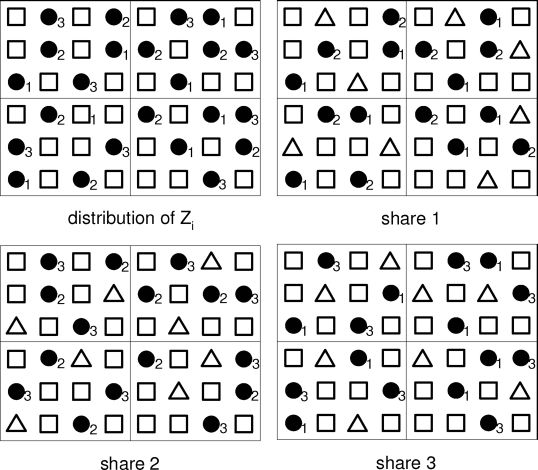
FIGURE 1.6
Upper left: distributions Zi, i = 0,1,…, 3. □ indicates pixels within Z0; •i indicates pixels within Zi. Upper right: distribution of SIPs and ABPs in share 1. Down left: distribution of SIPs and ABPs in share 2. Down right: distribution of SIPs and ABPs in share 3. •i indicates ABP and Δ indicates pixels used to carry share visual information. (Reprinted with permission from IEEE Trans. Inf. Forensics Security, vol. 4, no. 3, pp. 383–396, Sep. 2009 © IEEE 2009).
The configuration matrix helps to generate the distribution of ABPs. It should be noted that there is no need to find out the exact x ABPs in each halftone cell. The number x only characterizes the local density of the ABPs. We also only need to ensure that the contrast condition of the image decoding is satisfied.
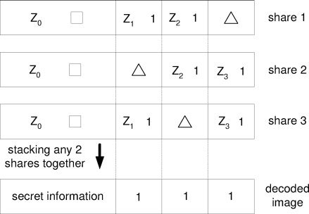
FIGURE 1.7
Composition of shares. □ indicates SIPs; 1 indicates ABPs; ∆ indicates pixels to carry the share visual information. (Reprinted with permission from IEEE Trans. Inf. Forensics Security, vol. 4, no. 3, pp. 383–396, Sep. 2009 © IEEE 2009).
1.3.3 Generation of Halftone Shares via Error Diffusion
After the distributions of SIPs and ABPs are generated, the next step is to assign the values to all the SIPs. This procedure only depends on the underlying VSS scheme. Under the k-out-of-n VSS scheme, the basis matrices S0 and S1 are constructed first. Then we construct the matrix collections C0 and C1 from the basis matrices. For each γ SIPs of a halftone cell, a matrix M is randomly selected from C0 or C1 depending on the value of the corresponding secret image pixel p. The SIPs in the ith share are then replaced with the ith row of M. sij, the jth SIP in share i, is set as: sij· = M(i, j). For the ABPs, they are assigned value 1 (black). Thus, the locations and the values of the SIPs and ABPs are set before halftone shares are actually generated. As it will be described below, the pixels other than ABPs and SIPs are assigned freely to carry the share visual information.
Once the assignments of the SIPs and ABPs are determined, a halftoning algorithm, such as error diffusion and direct binary search (DBS) [1], can be employed to produce the halftone shares from grayscale images. Error diffusion is used in our method as it is a computationally efficient way to generate halftone shares. The basic computation required is linear filtering followed by quantization.
The process of generating halftone shares via error diffusion is shown in Figure 1.8, where the values of the SIPs and ABPs are preset. To produce the halftone share i, a grayscale image is provided. Let fi(m, n) be the (m, n)th pixel of the grayscale image, then the input to the threshold block is:
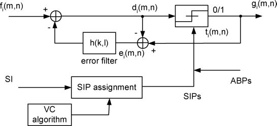
FIGURE 1.8
Block diagram of halftone VSS using the first method. Depending on the secret image and VSS scheme chosen, the SIP assignment block outputs the SIPs. If gi(m, n) is a SIP or ABP, its value is prefixed. Otherwise, gi(m, n) is determined by the output of the thresholding block. (Reprinted with permission from IEEE Trans. Inf. Forensics Security, vol. 4, no. 3, pp. 383–396, Sep. 2009 ©IEEE 2009).
where h(k, l) ∈ H and H is a two dimensional error filter. Here 0 < α ≤ 1 is an error diffusion constant that can be tuned to avoid instability in error diffusion [24]. A α < 1 means that not all quantization errors are diffused, which can prevent instability under excessive quantization errors. ei(m, n) is the quantization error at point (m, n). Assume the threshold for the error diffusion is ti(m, n), then the output halftone pixel gi(m, n) is 1, if di(m, n) > ti(m, n); or 0, if di(m, n) ≤ ti(m, n). The quantization error ei(m, n) is given by:
The above procedure is applied only when gi(m, n) is not a SIP or an ABP. Otherwise, instead of simple thresholding, the value of the output pixel gi(m, m) is set equal to the value of the corresponding predetermined SIP or ABP and the error ei(m, n) is calculated as the difference between the input to the thresholding block and the SIP or ABP value. Since the SIPs and ABPs are separated from each other, the quantization error caused by the introduction of the SIPs and ABPs is diffused away to the neighboring grayscale pixels, as illustrated in Figure 1.8, and will not accumulate to cause visible distortion. In this way, the SIPs and ABPs are seamlessly embedded into the halftone shares generated and the halftone share is structured taking meaningful visual information.
Much like the methods in [26, 25], the above procedure can be extended to an arbitrary access structure (ΓQual, ΓForb). The security of the introduced halftone VSS scheme is guaranteed by the properties of the underlying visual secret sharing scheme.
1.4 Halftone VSS Construction Using Parallel Error Diffusion
In the previous method, uniformly distributed auxiliary black pixels are introduced to satisfy the contrast condition of image decoding. The current method exploits the fact that halftoning of the grayscale images alone may generate a sufficient number of black pixels to block the shared visual information from showing on the decoded image.
As in the previous method, in the current method, the shares are also divided into nonoverlapping halftone cells of size q = v1 × v2. γ pixels within the halftone cell are SIPs carrying the secret visual information. A method based on error diffusion is used to generate the distribution of SIPs. To this end, a constant-value grayscale image of gray level z0 = γ/q, having the same size of a share image is first produced. This grayscale image is then halftoned, producing a distribution of “1”s, denoted by Z0. Z0 determines the distribution of the SIPs. To ensure that there are exactly γ “1”s in each halftone cell, the error diffusion is constrained such that the values of some pixels are preset and are not modified by the error diffusion. The error e(m, n), which is the difference between the input to the thresholding block and the resultant pixel value, is still calculated for the preset pixels and then diffused away to neighboring grayscale pixels through the error filter. In this constrained error diffusion mechanism, if the current halftone cell already contains γ “1”s, the rest of the pixels in the halftone cell are prefixed and constrained to be “0”s. The quantization error is accumulated and diffused to grayscale pixels in neighboring cells. If the current halftone cell contains t < γ “1”s, and the error diffusion already proceeds to the (q − γ − t)th pixel of the current cell, then the rest of the γ − t pixels in that cell are all constrained to be “1”s. This procedure guarantees that there are exactly γ SIPs in each halftone cell. Since the errors are always diffused to neighboring grayscale pixels, a homogeneous distribution of SIPs is produced, where most of the SIPs are well separated from each other. The assignment of SIPs are predetermined using the same approach as described previously.
Then, the current method halftones the grayscale images in parallel to produce the halftone shares. Within the error diffusion process, all the shares are checked at each non-SIP position to see if a sufficient number of black pixels have been produced. If a sufficient number of black pixels have not yet been generated, black pixels are deliberately inserted at that position. The SIPs are again preserved and not changed.
In a k-out-of-n scheme, if only τ < n − k + 1 black pixels are generated by halftoning at a non-SIP location (i, j), then λ = n − k + 1 − τ shares with the smallest magnitudes of halftone error at ( i, j) are selected and black pixels are inserted at (i, j) on these shares. Thus, the contrast condition of image decoding is guaranteed. The quantization error caused by the inserted black pixels will be diffused away to neighboring grayscale pixels and pleasing halftone shares can be obtained. Since far fewer black pixels are deliberately introduced, the second method imposes fewer constrains on the error diffusion and thus it has the potential to achieve better image quality than that of the first method. However, to achieve uniform image quality of the whole share, we need to choose the grayscale images in a selective way.
It is clear that the decision to insert a black pixel or not depends on the image content of the shares. Thus, the inserted black pixels are not evenly distributed. In some regions of the image, the error diffusion mechanism is constrained by the SIPs. In some other regions, error diffusion is constrained not only by the SIPs but also by the inserted black pixels. Therefore, the image quality on some regions in the image may be better than the image quality on some other regions that exhibit more artifacts. The parallel approach may thus generate shares whose image quality is not consistent over the whole image. Such quality discrepancy may cause visible distortions. To mitigate such visible distortion, we need to minimize the number of black pixels inserted. An obvious way to mitigate the distortion is to select grayscale images where the contents of some images tend to be complimentary to those of the others. For example, if there is one bright (white) region on one image, there should be corresponding dark region(s) in some other image(s). Then the halftoning of the grayscale images will generate most of the black pixels needed and the number of inserted black pixels will be greatly reduced, which leads to visually pleasing halftone shares. In a n-out-of-n scheme, if n ≫ 1, then this approach is especially effective and the visible distortion is less likely to happen.
1.5 Quality of Halftone Shares
In this section, we focus on the quality analysis of the halftone shares for the first method. The analysis also helps to evaluate the share image quality of the second method. With the exception of the SIPs and the ABPs, all pixels in the halftone share produced by the first method are assigned freely to carry the shared visual information. The proportion of these pixels governs the image quality of the resultant halftone shares. The quantity s is called the quality index of the halftone share and is represented as:
where q is the halftone cell size, x is the number of ABPs in a cell, and γis the number of SIPs in a cell. A large s leads to good image quality of the halftone share. However, s cannot be arbitrarily large and it can be shown that:
Thus, the best image quality of a halftone share that can be achieved depends on k, n and the halftone cell size q. If k, n, and s are the design parameters, then q is calculated as:
Consider the 2-out-of-2 scheme. Assume q = 4, then it is calculated that x =1 and s = 0.25. Since s is small, the image quality of the share is not high. If q is larger, then better image quality can be expected. Furthermore, as q → ∞, s approaches 0.5. However, a larger q leads to worse contrast loss of the reconstructed image. As will be shown later, the contrast loss of the reconstructed image can be improved by filtering.
The quality of each share depends on the quality index s. We can compare the share image with the halftone image generated from the grayscale image without encoding any secret information and then compute the perceived error e between the coded and uncoded halftone image. The perceived error is calculated by employing an appropriate human visual system (HVS) model. See [11, 9] for details.
For the second method, it is difficult to determine the proportion of pixels that carry visual information of the shares. However, it is clear that for n ≫ 1 in a n-of-of-n scheme, the quantity s approaches:
which indicates potentially good image quality for a sufficiently large q.
Compared with methods in [26] and [22], the requirement of a complementary pair is removed and all shares generated carry natural images. From (1.12), it is clear that for the first method, the quality index is more correlated to {k, n} in the VSS scheme. A visually pleasing halftone image share can be obtained if n ≫ 1 and n − k is small, and if the HVC expansion q is sufficiently large. If small image quality discrepancy of the share is tolerable, then we should first consider the first method, especially if we have the flexibility to choose the grayscale images. If the grayscale images are carefully chosen, n ≫ 1, and n − k is small, then the distortion due to image quality discrepancy will be hardly noticeable. Otherwise, only the first method should be considered since it is the only method that guarantees uniform image quality of the shares without using complimentary shares.
1.6 Discussion
1.6.1 Improvement of Image Quality
As stated previously, the quality index s heavily affects the image quality of the halftone shares. A large s leads to visually pleasing halftone shares, but it also introduces higher contrast loss in the reconstructed images. The error filter employed in the error diffusion also affects the image quality of the shares. For example, an error filter with longer weights leads to a sharper contrast in the halftone image [20, 14]. Another factor that affects the image quality is the position-dependent threshold in the thresholding block. To achieve a visually more pleasing halftone image, output-dependent threshold modulation can be used in the error diffusion to spread the minority pixels as homogeneously as possible and suppress some unwanted textures [6]. For various methods that can improve the halftone image by error diffusion, refer to [20, 6, 17, 21], etc.
Error diffusion is employed as the halftoning algorithm to generate halftone shares since error diffusion is able to generate a visually pleasing halftone image with simple computation. However, other halftoning algorithms can also be applied to the second method to generate halftone shares. The DBS algorithm can be used to generate a high quality halftone image but with significant computation [1]. Note that the DBS algorithm for multitoning can also be used to generate the distributions of SIPs and ABPs.
1.6.2 Comparison with Other Methods
To evaluate the performance of the introduced methods, it is illustrative to compare our methods with VC and extended visual cryptography (EVC) [3]. VSS can be treated as a special case in our methods for s = 0, which means that no visual information is carried by the share. In EVC, shares carry visual information and there is a tradeoff between the contrast of the reconstructed image and the contrast of the share image. This tradeoff is similar to the tradeoff between the contrast of the reconstructed image and the image quality of the halftone shares in our methods. However, the shares generated by EVC is basically based on pixels expansion. Thus, EVC is unable to generate shares that can show fine details.
1.6.3 Image Decoding
In the methods introduced in this chapter, a large HVC expansion is desirable to make s large. But the contrast loss of the decoded image is severe when the HVC expansion is large. However, a low contrast does not hinder the decoding of the secret image if the decoding can be performed digitally. Initially shares are supposed to be xeroxed on transparencies and decoding of the secret image involves stacking the shares physically. However, both the distribution of the shares and decoding of the secret image can be performed in a digital way where the decoding rule remains the same (OR operation). The human visual system is still the ultimate tool to identify the secret image.
The robustness of the introduced scheme to the contrast loss is attributed to the fact that shares have well-defined local structure. If decoded digitally, we can measure the local intensity of the reconstructed image by filtering the data through a running window. Then we measure the local intensity of the data within the window. We can assign 1 to the current pixel if the local intensity is relatively high and assign 0 to the current pixel if the local intensity is relatively low. By such a simple method, the contrast of the reconstructed image can be enhanced and the content is more readable. The size of the running window should be the same as the size of the halftone cell. However, if the halftone cell size is unknown, a proper window size can be obtained by trying different window sizes until only two different local intensities are most likely to appear.
1.7 Simulation Results

FIGURE 1.9
(a) Grayscale image Lena. (b) Part of the distribution of SIPs and ABPs. The gray pixels indicate SIPs and the black pixels indicate ABPs. (Reprinted with permission from IEEE Trans. Inf. Forensics Security, vol. 4, no. 3, pp. 383–396, Sep. 2009 ©IEEE 2009).
In this section, examples are provided to illustrate the effectiveness and tradeoff of the introduced methods. Constructions of 3-out-of-3 halftone VSS schemes are illustrated. The secret image to be encoded is the logo of the University of Delaware. Three grayscale natural images, Lena, Earth, and Baboon are provided to generate the shares. The size of the share is 513 × 513 and the size of the secret image is 171 × 171. For illustrative purposes, image Lena is shown in Figure 1.9(a).
The VSS pixel expansion of the secret pixel is γ = 4 and the size of the halftone cell is q = 3 × 3. The number of ABPs for each halftone cell is x = 2 and the quality index is s = 1/3. The distributions of SIPs and ABPs for each share are decided before halftone shares are generated. The jointly optimized distribution of SIPs and ABPs over a local region in one share is shown in Figure 1.9(b) where the gray pixels indicate SIPs and the black pixels indicate ABPs. We use the Floyd-Steinberg error filter shown in Figure 1.2 for the error diffusion. For robust error diffusion, output-dependent threshold modulation is employed and the threshold t(m, n) at the point (m, n) is given by:
The threshold modulation tries to adjust the current threshold by using the information of three preceding halftone pixels. For error diffusion, the error diffusion constant is set to α = 0.8 to avoid error diffusion instability.
Three output shares are shown in Figure 1.10(a) to Figure 1.10(c), respectively, where the corresponding perceived errors are also shown. When calculating the perceived error є, an alpha stable human visual system model proposed in [9] is used. All shares show visually pleasing halftone images where the image details can be clearly recognized. The resultant shares do not show either residue image of the encoded image or any residue image of other shares. Figure 1.10(d) shows the reconstructed image when shares 1 to 3 are “stacked” together with the Oi operation. The content of the reconstructed image is clearly recognizable with a contrast α = 1/9. The decoded image does not bear any residue of any share images.
To illustrate the tradeoff between the share image quality and contrast of the decoded image, we show another set of simulation results of a 3-out-of-3 halftone VSS scheme. Compared with the previous example, the halftone cell size is changed to q = 4 × 4. The sizes of the shared image and the secret image are well adjusted to be 512 × 512 and 128 × 128, respectively. The number of ABPs for each halftone cell is x = 4 and the quality index increases to s = 1/2. The three output shares are shown in Figure 1.11(a) to Figure 1.11(c), respectively, where the corresponding perceived error is also shown. Figure 1.11(d) shows the reconstructed image by stacking three shares together, where the contrast of the decoded image is α = 1/16. Shares in the second example have larger halftone cell size, thus larger s and better image quality than that of the shares in the first example, as can be seen from Figure 1.11. However, the contrast loss of the decoded image is worse. It is observed that the contrast of Figure 1.11(d) is lower than that of Figure 1.10(d).

FIGURE 22.1
(a)–(c) Shares of the 3-out-of-3 scheme using the first method, q = 9. The perceived errors are 1.73 × 10¹⁰, 8.45 × 10⁹, and 5.46 × 10⁹, respectively. (d) Decoded image by shares (a)-(c), α = 1/9. (Reprinted with permission from IEEE Trans. Inf. Forensics Security, vol. 4, no. 3, pp. 383–396, Sep. 2009 ©IEEE 2009).
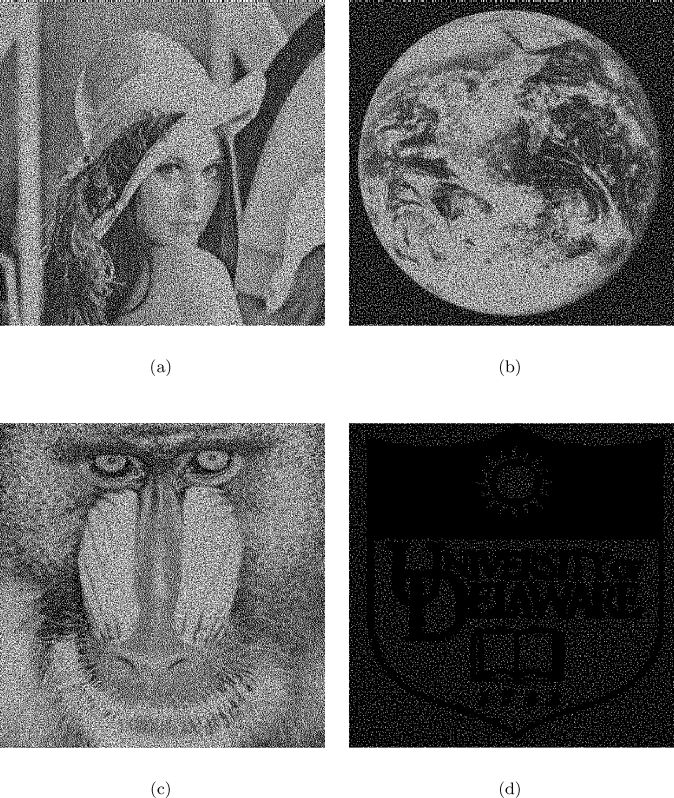
FIGURE 23.1
(a)–(c) Shares of the 3-out-of-3 scheme using the first method, q = 16. The perceived errors are 7.1 × 10⁹, 3.48 × 10⁹, and 2.27 × 10⁹, respectively. (d) Decoded image by shares (a)-(c), α = 1/16. (Reprinted with permission from IEEE Trans. Inf. Forensics Security, vol. 4, no. 3, pp. 383–396, Sep. 2009 ©IEEE 2009).

FIGURE 1.12
(a)–(c) Shares of the 3-out-of-3 scheme using the second method, q = 16. (d) Decoded image by shares (a)–(c), α = 1/16. (Reprinted with permission from IEEE Trans. Inf. Forensics Security, vol. 4, no. 3, pp. 383–396, Sep. 2009 ©IEEE 2009).
In the following, we present the halftone shares generated by using the second construction method. The performance of the second method is evaluated by comparing its shares with those of the first method. Figure 1.12(a)–(c) show three shares produced using the second method in a 3-out-of-3 scheme where the size of the image is 512 × 512 and the size of the halftone cell is 4 × 4. Here, images Lena, Tank, and Baboon are used. It is obvious that all halftone shares show images with fine details. The reconstructed image is shown in Figure 1.12(d), which preserves all the secret information. Compared with Figure 1.12(a), Figure 1.11(a) is generated using the first method, showing less image details and appearing dark due to the added ABPs.

FIGURE 25.1
(a)–(c) Another set of shares generated by the second method, q = 16, depicting more pronounced artifacts. (Reprinted with permission from IEEE Trans. Inf. Forensics Security, vol. 4, no. 3, pp. 383–396, Sep. 2009 ©IEEE 2009).
We should point out that the second method does not necessarily produce visually pleasing halftone shares if the grayscale images are not carefully selected. As an example, Figure 1.13(a)–(c) shows another set of shares generated by Lena, Earth, and Baboon using the second method with the same scheme. Careful inspection shows these shares present more artifacts due to the cross interference between the shares. The reason is that the contents of the three grayscale images are not complementary to each other. Comparing Figure 1.13(a) with Figure 1.11(a) and Figure 1.12(a), local geometric distortion can be observed in Figure 1.13(a). The texture of the distorted region is quite different from that of the neighboring regions, which causes visible artifacts. On the other hand, Figure 1.11(a) and Figure 1.12(a) both show smooth images with uniform image quality. Thus, it is important to choose appropriate grayscale images for the second method.
1.8 Conclusion
In this chapter, HVC construction methods based on error diffusion are introduced, which can generate shares with pleasing visual information. In the introduced methods, the pixels that carry the secret information are preset before a halftone share is generated from a grayscale image. Error diffusion is used to construct the shares so that the noise introduced by the preset pixels is diffused away when halftone shares are generated. The secret information is then naturally embedded into the halftone shares. The homogeneous and isotropic distribution of the preset pixels imposes the least noise in the error diffusion, thus leading to shares with high image quality. Our introduced methods follow the basic principle of VC, thus the security of the construction scheme is guaranteed. The introduced HVC constructions apply not only to VSS but also to VSS used in the context of visual authentication and encryption.
For the first method, by using auxiliary black pixels, the contrast condition of the decoded image is satisfied. Furthermore, the shares do not suffer any interference from other shares. When auxiliary black pixels are employed, blue noise multitone error diffusion is used to generate the distributions of the secret information pixels and black auxiliary pixels. The second method exploits the fact that halftoning of the graycale images alone can generate most of the black pixels needed. Black pixels are inserted only when a sufficient number of black pixels have not yet been produced. By carefully selecting the grayscale images, the second method can also generate shares with visually pleasing images. For both methods, the decoded image does not suffer any interference from the shared images. It is clear that there is a tradeoff between the shared image quality and the contrast loss of the decoded image. However, by simple linear filtering, the contrast loss can be easily recovered.
Bibliography
[1] M. Analoui and J. P. Allebach. Model-based halftoning using direct binary search. In Proc. SPIE, volume 1666, pages 96–108, Feb. 1992.
[2] G. Ateniese, C. Blundo, A. De Santis, and D. R. Stinson. Visual cryptography for general access structures. Information and Computation, 129((2):86–106, Sept. 1996.
[3] G. Ateniese, C. Blundo, A. De Santis, and D. R. Stinson. Extended capabilities for visual cryptography. Theoret. Comput. Sci., 250:143–161, 2001.
[4] J. Bacca, G. R. Arce, and D. L. Lau. Blue noise multitone dithering. IEEE Trans. Image Process., 17((8):1368–1382, Sep. 2008.
[5] C. Blundo, P. D’Arco, A. De Santis, and D. R. Stinson. Contrast optimal threshold visual cryptography schemes. SIAM J. Discrete Math., 16((2):224–261, 2003.
[6] R. Eschbach, Z. Fan, K. T. Knox, and G. Marcu. Threshold modulation and stability in error diffusion. IEEE Signal Process. Mag., 20:39–50, Jul. 2003.
[7] F. Faheem, D. L. Lau, and G. R. Arce. Digital multitoning using gray level separation. J. Imag. Sci. and Tech. , 46((5):385–397, Sep. 2002.
[8] M. S. Fu and O. C. Au. Joint visual cryptography and watermarking. In Proc. IEEE Int. Conf. on Multimedia and Expo, Taipei, Taiwan, Jun. 2004.
[9] A. J. Gonzalez, G. R. Arce, J. Bacca Rodriguez, and D. L. Lau. Human visual alpha-stable models for digital halftoning. In Proc. 18th Annual Symp. on Electron. Imag. Sci. and Tech.: Human Vision and Electro. Imag. XI, San Jose, CA, Jan. 2006.
[10] A. Houmansadr and S. Ghaemmaghami. A novel video watermarking method using visual cryptography. In Proc. IEEE Int. Conf. on Engineering of Intelligent Systems, Islamabad, Pakistan, Apr. 2006.
[11] S. H. Kim and J. P. Allebach. Impact of HVS models on model-based halftoning. IEEE Trans. Image Process., 11((3):258–269, Mar. 2002.
[12] D. L. Lau and G. R. Arce. Modern Digital Halftoning. Marcel Dekker, Inc, 2001.
[13] D. L. Lau, G. R. Arce, and N. C. Gallagher. Green-noise digital halftoning. Proceedings of the IEEE, 86((12):2424–2444, Dec. 1998.
[14] D. L. Lau, G. R. Arce, and N. C. Gallagher. Digital halftoning by means of green-noise masks. J. Opt. Soc. Am. A-Optics Image Sci. and Vis., 16((7):1575–1586, Jul. 1999.
[15] D. L. Lau, G. R. Arce, and N. C. Gallagher. Digital color halftoning with generalized error diffusion and multi-channel green-noise masks. IEEE Trans. Image Processing, 9((5):923–935, May 2000.
[16] D. L. Lau, R. Ulichney, and G. R. Arce. Blue- and green-noise halftoning models—a review of the spatial and spectral characteristics of halftone textures. IEEE Signal Processing Magazine, 10((4):28–38, Jul. 2003.
[17] P. Li and J. P. Allebach. Tone-dependent error diffusion. IEEE Trans. Image Process., 13((2):201–215, Feb. 2004.
[18] M. Naor and B. Pinkas. Visual authentication and identification. Crypto97, LNCS, 1294:322–340, 1997.
[19] M. Naor and A. Shamir. Visual cryptography. Advances in Cryptography: EUROCRYPT'94, LNCS, 950:1–12, 1995.
[20] R. A. Ulichney. Dithering with blue noise. In Proc. the IEEE, volume 76, pages 56–79, Jan. 1988.
[21] N. D. Venkata and B. L. Evans. Adaptive threshold modulation for error diffusion halftoning. IEEE Trans. Image Process., 10((1):104–116, Jan. 2001.
[22] Z. Wang and G. R. Arce. Halftone visual cryptography through error diffusion. In Proc. IEEE ICIP, Atlanta, GA, Oct. 2006.
[23] Z. Wang and G. R. Arce. Halftone visual cryptography via error diffusion. IEEE Trans. Inf. Forensics Security, 4((3):383–396, Sep. 2009.
[24] C. W. Wu and G. Thompson. Digital watermarking and steganography via overlays of halftone images. In Proc. SPIE, volume 5561, pages 152–163, Oct. 2004.
[25] Z. Zhou, G. R. Arce, and G. Di Crescenzo. Halftone visual cryptography. In Proc. IEEE Int. Conf. on Image Process., Barcelona, Spain, Sep. 2003.
[26] Z. Zhou, G. R. Arce, and G. Di Crescenzo. Halftone visual cryptography. IEEE Trans. Image Process., 15((8):2441–2453, Aug. 2006.