
4
Extended Visual Cryptography for Photograph Images
Yasushi Yamaguchi
The University of Tokyo, Japan
Japan Science and Technology Agency / CREST, Japan
CONTENTS
4.2 Basic Visual Cryptography Schemes
4.3 Fundamentals of Photograph Visual Cryptography
4.4 Variations of Photograph Visual Cryptography
4.4.1 Approaches to Photograph Visual Cryptography
4.4.2 Random-Dot Shadow Images
4.4.4 Positive and Negative Shadow Images
4.4.5 Error and Secret Diffusion
4.1 Introduction
Visual cryptography is a kind of cryptography that can be decoded directly by the human visual system without any computation for decryption. It usually prints certain images on transparencies and the secret image is reconstructed by simply stacking the transparencies together. Extended visual cryptography allows the printing of meaningful images on transparencies so that it can conceal the very existence of secret in the transparencies. There have been a lot of studies to incorporate photograph images into extended visual cryptography. This chapter attempts to survey the studies on extended visual cryptography for photograph images.
4.2 Basic Visual Cryptography Schemes
In order to determine basic terminology in this chapter, this section explains basic concepts of visual cryptography, namely, k out of n Visual Secret Sharing Scheme ((k, n) VSSS), an Extended Visual Cryptography Scheme (EVCS), and Random Grids.
4.2.1 (k,n) Visual Secret Sharing Schemes
This scheme was proposed by Naor and Shamir in 1994 [31]. It generates n transparencies from an original secret image. The transparencies are usually shared by n participants so that each participant is expected to keep one transparency. Thus, a secret image is sometimes called a shared image. The secret image can be observed if any k or more of them are stacked together. However, the secret image is totally invisible if fewer than k transparencies are stacked. The images on transparencies are called shadow images.
Each pixel of a shadow image is generated separately in the conventional VSSS. An original secret pixel will be transformed to n patterns of pixels for shadow images. These pixels on shadow images are called shares. A share consists of m black and white subpixels. The human visual system observes the average of subpixels, because they exist in close proximity. This structure is usually described by an n × m Boolean matrix M = [mij]. Here mij = 0 or 1 if the jth subpixel in the ith shadow is white or black, respectively. If transparencies of r shadows i1, i2, ? , ir out of n are stacked in a way that properly aligns the subpixels, each combined share can be represented by the Boolean OR of the corresponding rows i1, i2, ? , ir in the Boolean matrix M. Let Mr denote the m-D vector obtained by taking the Boolean OR of r row vectors. The gray level of a pixel combined by r shares is obtained by the Hamming weight H(Mr) of the ORed m-D vector Mr. Users interprets this gray level as black if H(Mr) = t and as white if H(Mr) < t - am. Here, t ? {1, ? , m} is called threshold, while the value a > 0 and the number am = 1 are called relative difference and contrast, respectively.

FIGURE 4.1
Six possible patterns of subpixel arrangements with 50% gray. Each pattern is represented as [0 0 1 1], [1 10 0], [0 10 1], [1 0 10], [0 11 0], [10 0 1] from left to right.
The (k, n) VSSS consists of two collections of n ՠm Boolean matrices Cw and Cb where any matrix in Cw generates a white pixel with k or more of shares (rows) while a matrix in Cb generates a black pixel. The scheme is valid if it fulfills the following three conditions:
For any M in Cw, the OR ed vector Mk of any k rows of M satisfies H(Mk) < t - am.
For any M in Cb, the OR ed vector Mk of any k rows of M satisfies H (Mk) = t.?
For any subset {i, i2, ?, iq} of {1, 2, ?, n} with q < k, the two collections of q ՠm matrices ?w and ?b obtained by extracting rows i1, i2, ?, iq from n ՠm matrices in Cw and Cb are indistinguishable so that the collections contain the same matrices with the same frequencies.
The above first two conditions are contrast conditions that k or more of shadow images can recover the secret image with contrast am. The recovered secret image is usually called the reconstructed image. The last condition is related to security, which implies that none can gain any information on the secret image by investigating fewer than k shadow images.
Here, two parameters m and a are very important to this discussion. The parameter m indicates the number of subpixels in a share, which is called pixel expansion. Each pixel of the original secret image is represented by m subpixels so that the reconstructed image as well as the shadow images will be m times large as the original image. People would like m to be as small as possible. The parameter a indicates the relative difference between combined shares of an originally white pixel and an originally black pixel. Since it means the loss of contrast of the reconstructed image, people would like a to be as large as possible.

FIGURE 98.4
An example of visual secret sharing scheme (VSSS). Two shadow images of random patterns (left and middle) and reconstructed secret image (right).
Let us consider a special case of (2, 2) VSSS. Each share consists of 4 subpixels of a 2 ՠ2 array in a physical implementation, where two of them are white and the rest two are black. The Boolean matrix of this scheme is 2 ՠ4 where each row consisting of two 0s and two 1s represents an arrangement of subpixels in a share. For instance, six possible patterns of shares having 50% gray as shown in Figure 4.1 are represented as {[0 0 1 1], [1 1 0 0], [0 1 0 1], [1 0 1 0], [0 1 1 0], [1 0 0 1]}. The scheme is accomplished by the following two collections:
where Sw and Sb are given as below:
The above matrices Sw and Sb are called basis matrices. Because the collections are obtained by permutation of subpixels, each share may have randomly arranged two white and two black subpixels, which looks 50% gray. A pair of shares from Cw has the same arrangement of subpixels. The combined result is the same pattern, which looks 50% gray. A pair of shares from Cb has the complementary arrangement of subpixels. The combined result consists of four black subpixels, which looks completely black. Figure 4.2 shows an example of resulting shadow images and a reconstructed secret image. The size of all images are 128 ՠ128 pixels, because the original secret image has 64 ՠ64 pixels.
The original scheme proposed by Naor and Shamir is uniform, such that any combined shares from q < k shadow images yield ORed m-D vector Mq with H(Mq) = f (q) with uniform probability distribution, regardless of if the matrices were taken from Cw or Cb. Suppose the case of q = 1, the above-mentioned combined share is a single share of each shadow image. It means all the shadow images consist of uniformly random pattern of black and white subpixels. Naor and Shamir pointed out an extension of this scheme for concealing the very existence of the secret image.
4.2.2 Extended Visual Cryptography Scheme
Ateniese et al. extended the VSSS in the sense of a General Access Structure (GAS) [1] and extended capability. [2] A General Access Structure controls the qualified set of transparencies with which one can recover the secret image, while any k or more transparencies can reconstruct the secret image in (k, n) VSSS. An extended capability is able to introduce a meaningful image as a shadow image which Naor and Shamir pointed out in their very first paper [31]. An innocent-looking image of a house, dog, or something else would be much less suspicious than a random-dotted image as a shadow image.
In the Extended Visual Cryptography Scheme (EVCS), for an access structure (GQual, GForb) on a set of n participants, the shared (secret) image can be recovered by any qualified set X ? GQual with no trace of the shadow images, but any forbidden set X ? GForb has no information on the secret image. Moreover, the shadow images are meaningful so that each participant can recognize the image on ones transparency.
Similar to the (k, n) VSSS, an EVCS can be constructed in a pixel-wise manner. Since n participants share one secret image and have their own images in the n shadow images, we have to consider n +1 colors, c, c1, ? ,cn ? {w, b} where w and b stands for white and black, respectively. The value c denotes the color of the secret image pixel and ci denotes the color of the original image pixel for i-th participants shadow image. In order to realize an EVCS that obtains a c pixel when transparencies associated to a set X ? GQual, we need 2n pairs of collections of n ՠm Boolean matrices, , one for each possible combination of white and black pixels in the n original images for the shadow images.
An EVCS for an access structure (GQual, GForb) for n participants is valid if it fulfills the following conditions.
For any X ? GQual and for any c1, ?, cn ? {b, w}, the threshold tX and the relative difference aR exist, which satisfy H(MX) = tX - aRm for any and H(MX) = tX for any . Here MX denotes the m-D vector obtained by taking Boolean OR of the row vectors of M corresponding to the participants in X and H(MX) denotes the Hamming weight of the vector MX.
For any X = {i1, ?, iq} ? GForb and for any c1, ?, cn ? {b, w}, the two collections of q ՠm matrices, and , obtained by extracting rows i1, ?, iq from each n ՠm matrix in and , respectively, are indistinguishable so that the collections contain the same matrices with the same frequencies.
For any i ? {1, 2, ?, n} and any c1, ?, ci-1, ci+1, ?, cn ? {b, w}, it results that
where
and H(Mi) denotes the Hamming weight of the i-th row vector Mi of a matrix M.
The values aR > 0 and aS > 0 are referred to as the relative difference of the reconstructed image and relative difference of shadow images, respectively. The number aRm = 1 and aSm = 1 are contrasts of the reconstructed image and the shadow images. People would like both aR and aS to be as large as possible.
The first condition is the contrast condition that indicates any qualified set X ? GQual can recover the secret image. The secret image can be recovered by stacking the transparencies of a qualified set, belonging to GQual. The second condition is the security condition that states any forbidden set X = {i1, ?, iq} ? GQual has no information on the secret image. People cannot get any information on the secret image by inspecting the shadow images of a forbidden set. The third condition is the extended condition that implies that the shadows images are still meaningful after the original images are encoded. Any participant can recognize the shadow image on ones transparency. Although the collection Mb is obtained by combining two collections and , we have the same set of {Mi} only with one of the collections, because for any c1, ?, cn ? {b, w} and any i ? {1, ?, n} due to the second condition.
Here we show how to accomplish a 2 out of 2 EVCS. Each share consists of 4 subpixels like (2, 2) VSSS. However, it contains either two 1s or three 1s depending on the colors of pixels of the corresponding original image, white or black, respectively. The scheme is given by the 4 pairs of collections , namely 8 collections , where c, c1,c2 ? {b, w}. The collections are obtained by permuting the columns of the following 8 basic matrices, :

FIGURE 101.4
An example of extended visual cryptography scheme (EVCS). Two resulting shadow images (left and middle) and reconstructed secret image (right).
The reconstructed pixel has 3 or 4 black subpixels if the original secret pixel is white or black, respectively. In this scheme, the relative contrasts are given as . Figure 4.3 shows an example of resulting shadow images and reconstructed secret image. The size of all images are 128 ՠ128 pixels, because all the original shadow and secret images have 64 ՠ64 pixels.
Ateniese et al. also pointed out some of the most important aspects of the extended capability [2]. One is related to the contrasts of images. A trade-off between two relative differences exists, aR and aS, in any (k, k) EVCS as below:
This means we cannot increase both contrasts of a reconstructed image and shadow images, aRm and aSm, simultaneously. They also specified the lower bound of the pixel expansion m in (k, k) EVCS as below:
This means we need more pixels to obtain EVCS. Although people would like contrasts to be as large as possible and pixel expansion as small as possible, there exist certain limits of them.
4.2.3 Random Grids
Random Grids (RG) give a very different approach to visual cryptography, which can keep the size of resulting shadow images to be the same as that of the original image. In other words, the pixel expansion of this method is m =1 and no more expansion problems exist. The method is first introduced by Kafri and Keren in 1987 [17] and reinvestigated by Shyu in 2007 [37]. A random grid R is defined as a two-dimensional array of pixels. Each pixel is either transparent (white) or opaque (black) by a coin-flip procedure. The numbers of transparent pixels and opaque pixels are probabilistically same and the average opacity1 of a random grid is 50%:

FIGURE 4.4
An example of random grid (RG). Two random grids (left and middle) and reconstructed secret image (right).
Let R(p) denote a pixel value of the random grid R at the position p and denote its inverse.
We must note that the inverse of a random grid is also a random grid and its opacity is 50 %, . The superimposition of two random grids, R1 and R2, pixel by pixel is computed by taking Boolean OR operation of their corresponding pixels, R1(p) and R2(p), as VSSS and EVCS:
It is obvious that the superimposition of the same random grids results in the original random grid. The superimposition of a random grid and its inverse is a grid whose pixels are all opaque. Thus, the average opacity will be as below:
The encryption algorithm for a binary image B, which generates a pair of random grids R1 and R2 that can achieve the highest contrast is as follows.
Algorithm
Generate a random grid R1 with the same size as B.
For each pixel B(p), a grid R2 is determined as below:
Let T and O denote transparent and opaque regions of the original binary image B so that and . The regions T and O fulfills the following constraints:
where O stands for the entire region of the original image while ? represents the null region, because B is a binary image. Due to the definition of the above algorithm, random grids R1 and R2 satisfies the following relations:
Therefore, R2 as well as R1 is a random grid and the average opacity of their superimposition depends on the regions T and O of the input binary image:
The difference of the average opacities of region T and O corresponds to relative difference a in VSSS. Figure 4.4 shows an example of random grids and a reconstructed secret image. The size of all images are 64 ՠ64 pixels, which is the same as that of the original secret images, because Random Grids are free from pixel expansion, m = 1.
4.3 Fundamentals of Photograph Visual Cryptography
Digital cameras have become very popular and people can easily obtain continuous-tone digital image data. However, all the schemes explained in the last section accept binary images as input. Thus, a photograph image must be converted to a binary image that can be observed similar to the original image by the human visual system. The algorithm that can achieve such a conversion is referred as digital halftoning or halftoning in short [38, 18].
4.3.1 Digital Halftoning
There are several approaches to digital halftoning, namely, noise-encoding, ordered dither, error diffusion, iterative and search-based methods, etc. Here we explain some of the approaches.

FIGURE 104.4
Samples of ordered dither matrices. Clustered-dot matrix (left) and dispersed-dot matrix (right).
Density Pattern
It is obvious to achieve (l + 1) gray levels, i.e., tones, with l binary pixels. The density pattern method uses l subpixels for representing each pixel value. This is similar to the visual cryptography in the sense that a resulting image requires more pixels than the original image. If we adopt this type of halftoning method, the resulting shadow images and reconstructed secret image are lm times larger than the original continuous-tone images. Of course, this is inappropriate since people want to make a resulting image as small as possible.
Noise-Encoding
The easiest way to obtain a binary image from a continuous-tone image of the same size is thresholding, which assigns 0 to a pixel of the resulting binary image if the original pixel value is smaller than a threshold value. Otherwise it assigns 1 to the binary pixel. However, the resulting binary image usually suffers from pseudo-contours. Noise-encoding is a key concept for improving image quality. In the early stage of digital halftoning studies, random noise, i.e., white noise, is used for this purpose. A binary image obtained by adding random noise followed by thresholding yields better quality than a simply-thresholded image, because it reduces pseudo-contours. Random dither is a simple extension of noise-encoding. It uses a random threshold array and thresholds each pixel with a random number instead of using a constant threshold after adding a random number to the pixel value.
Ordered Dither
Noises need not be random and a threshold matrix can be generated with a certain order. Ordered dither generates a binary image by comparing a pixel of an original continuous-tone image with a threshold value of the periodic ordered matrix. The methods based on ordered dither are classified into two categories, clustered-dot ordered dither, and dispersed-dot ordered dither depending on the nature of generated dots.
Clustered-dot ordered dither turns adjacent pixels on which form a cluster in the matrix. The period length of dots is determined by that of the matrix. The tone level of a region is modulated by the area size of clustered-dot. Thus, this method is categorized as an amplitude modulation (AM) technique. A spiral-dot screen, whose sample threshold matrix is shown in Figure 4.5 left, is a kind of cluster-dot ordered dither.
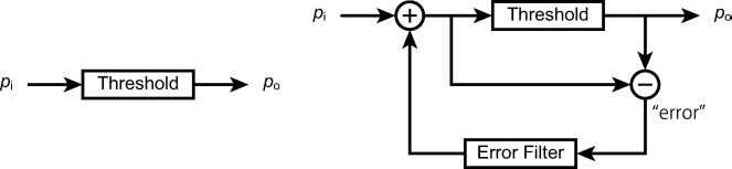
FIGURE 4.6
Diagrams of point process and error diffusion.
Dispersed-dot ordered dither turns scattered pixels on without making any clusters. The result may have a high-frequency fidelity and better appearance in constant gray regions. Thus, people prefer dispersed-dot ordered dither to clustered-dot ordered dither. The tone level of a region is modulated by the density (or frequency) of dots. Thus, this method is categorized as a frequency modulation (FM) technique. A famous Bayers matrix shown in Figure 4.5 right is an example of dispersed-dot ordered dither.
Error Diffusion
The above-mentioned approaches are said to be point process in a sense that each point (or pixel) is processed independently. In other words, an output value of a pixel depends only on a value of the input pixel as shown in Figure 4.6 left. Error diffusion, a commonly-used halftoning algorithm, takes a neighborhood into account so that it is no more a point process. It is an adaptive algorithm that uses the threshold error feedback to produce patterns having different spatial frequency content. A single pass is carried out over the input image each pixel of which is processed sequentially. A single pixel process consists of a binary thresholding of the input pixel and an error computation caused by the binarization. This error is distributed to the neighboring pixels that have not been processed according to an error filter (or error matrix). Famous error filters proposed by Floyd and Steinberg [8] and Jarvis et al. [16] are shown in Figure 4.7 where X indicates the current pixel. In other words, the values of neighboring pixels are corrected to keep the total tone of a local region. The schematic diagram of the algorithm is illustrated in Figure 4.6 right.
Iterative and Search-Based Methods
Iterative and search-based methods attempt to obtain the optimum solution as a halftoned image by iteration and/or search manner. Since the ultimate goal of digital halftoning is to accomplish an illusion of a binary image that is observed completely same as the original continuous-tone image, the method tries to minimize the perceived difference between the binary image output and the original image. The perceived error is estimated by a spatial filter that simulates a human visual system as well as the output device model. Direct binary search is one of the popular methods of this kind. The schematic diagram of this method is illustrated in Figure 4.8.
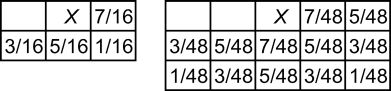
FIGURE 4.7
Samples of error filters for error diffusion proposed by Floyd and Steinberg [8] (left) and Jarvis et al. [16] (right).

FIGURE 4.8
A diagram of iterative and search-based method.
4.3.2 Image Quality and Related Parameters
Let us discuss quality of resulting images in terms of its parameters in this section.
Tone levels (l) Due to the nature of the visual cryptography scheme, the input images, namely, the original images as a secret image and shadow images, must be binary. This is a big limitation in the sense of image quality, especially for photograph images. Halftoning allows us to convert a continuous-tone image to a binary image that can be observed similar to the original image by human eyes. However, the halftoned image is not completely the same as the original image. It may lose a certain quality of photograph images. On the contrary, some types of images, such as images of logos or text, are still meaningful even if the tone levels are limited to two or three.
Pixel expansion (m) Pixel expansion is also an important parameter that affects quality of images as well as its data size. The resulting image requires m times more subpixels, which means that subpixels must be m times smaller than the original pixel if the image size is fixed to that of the original image. This results in difficulty of alignment so that transparencies with smaller subpixels are more difficult to be stacked properly. Misaligned transparencies cannot reconstruct the secret image. This cannot be neglected because one of the most important characteristics of visual cryptography is the capability that the secret information is revealed by simply stacking transparencies without any computation.
Relative difference (a) It is obvious that contrast is also one of the most important parameters related to image quality. An image with low contrast is obscure and difficult to see its details. Furthermore, there exists a certain tradeoff between contrasts of shadow and secret images in case of extended visual cryptography. It is impossible to increase both contrasts of a secret image and shadow images simultaneously.
4.3.3 Photograph Visual Cryptography with Basic Schemes
The straightforward way to incorporate photograph images into visual cryptography is as below:
Convert photograph (continuous-tone) images to binary images by halftoning.
Encrypt a secret image by one of the schemes explained in Section 4.2.
Of course the quality of resulting images may be changed by the halftoning algorithm. But here we would like to focus on the differences among the encryption schemes.
Table 4.1 summarizes the characteristics of visual cryptography with photograph images according to the encryption schemes, i.e., Visual Secret Sharing Scheme (VSSS), Extended Visual Cryptography Scheme (EVCS), and Random Grids (RG), in the case of (2, 2). Since all three schemes assume that shadow images are printed on transparencies and stacked together, the superimposition (stacking operation) can be seen as Boolean OR in mathematical sense. The basic properties of VSSS and RG are very similar except for the pixel expansions. The pixel expansion of (2, 2) VSSS is m = 2 (it would be 4 if one wants to preserve the aspect ratio of a image), while RGs pixel expansion is m = 1. VSSS and RG have no extended capability. They cannot incorporate photograph images into shadow images in order to conceal the existence of secret, which means the original shadow images are simple monotone images (mono.) and encrypted results are random-dot binary images (rand.). In other words, the relative difference of shadow images is aS = 0. However, they can accept a continuous-tone image (cont.) as a secret image. A reconstructed secret image is a halftoned binary image (half.) whose relative difference is . Only EVCS among the three basic schemes can incorporate continuous-tone images into shadow images. The resulting shadow images to be printed on transparencies and reconstructed secret image by stacking shadow images are binary images converted by halftoning. The pixel expansion of (2, 2) EVCS is m = 4. A tradeoff between relative differences of shadow image and reconstructed image exists. If we restrict both relative differences to be the same, the maximum relative differences are .
Table 4.1 Comparison of visual cryptography schemes, namely, VSSS, EVCS, and RG, with photograph images in the case of (2, 2). Here, m denotes the pixel expansion of each scheme. aS and aR stand for relative differences of shadow images and reconstructed secret image, respectively. and denote the tone levels of original images to be processed, while lS and lR denote the tone levels of the resulting (encrypted/decrypted) images. Strictly speaking, lS and lR should be 2, because every resulting image consists of white and black subpixels. However, for human visual system, an image can be observed as a gray-scale image because of halftoning. In this sense, we specify lS > 2 for EVCS and lR > 2 for all three schemes. mono., cont., half., and rand. mean a monotone image, continuous-tone image, halftoned binary image, and random-dot binary image, respectively.
| shadow image | secret image | ||||||
| scheme | m | aS | lS | aR | lR | ||
| VSSS | 2(4) | 0 | 1 (mono.) | 1 (rand.) | 1/2 | 8 (cont.) | >2 (half.) |
| EVCS | 4 | 1/4 | 8 (cont.) | > 2 (half.) | 1/4 | 8 (cont.) | >2 (half.) |
| RG | 1 | 0 | 1 (mono.) | 1 (rand.) | 1/2 | 8 (cont.) | >2 (half.) |
4.4 Variations of Photograph Visual Cryptography
Although extended capability is a crucial aspect for visual cryptography with a photograph image, contrast of resulting images becomes very low ( at maximum) due to the tradeoff between relative differences of the shadow image and reconstructed image. Contrast tends to much lower if the number of shadow images increases. In order to enhance contrast of encrypted images, several researches assumed other kinds of operations for superimposition, namely, Cover, [32] XOR, [3, 23] NOT, etc. [40] Sometimes even a certain computation is required for decryption [5, 20, 24]. Most of the approaches are no longer realized by stacking transparencies.2 Those schemes may not be categorized as visual cryptography, because the most important characteristics of visual cryptography is the capability of visual decryption without any computation. Therefore, we will not discuss these type of approaches assuming other operations than Boolean OR. Instead our discussion will mainly focus on (2, 2) schemes. There have been a lot of studies that aim at incorporating color into visual cryptography [27, 35, 39, 22, 44, 12, 13, 7, 30, 36, 46, 19]. These approaches are strongly related to the techniques for handling continuous-tone images. However, this chapter will not discuss those color studies because this book contains a special chapter dedicated to color visual cryptography.
4.4.1 Approaches to Photograph Visual Cryptography
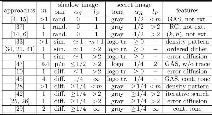
The main issue for incorporating photographs into visual cryptography is the quality of resulting images, i.e., pixel expansion, relative differences, tone levels, as we discussed in Section 4.3.2. A lot of approaches to photograph visual cryptography intend to improve the image quality by introducing a certain limitation and/or by exploiting image processing techniques. Table 4.2 summarizes those approaches. For instance, [4, 15, 37, 14, 6] limit their shadow image to a random-dot binary image (rand.). Actually they do not intend extended visual cryptography [33, 34, 21, 41, 9, 47]. Generate very similar images (sim.) or a positive/negative pair of images (p/n) as encrypted shadow images. Sometimes only logo-like images with the trace of shadows (logo tr.) can be reconstructed as a secret image [33, 34, 21, 41, 9, 10, 45]. [10, 25, 42] utilize halftoning techniques to make pixel expansion m = 1. [28, 42, 45, 25, 26] adjust tone, i.e., dynamic range, of images for improving image quality. Some studies introduce continuous-tone subpixels into encrypted shadow images to obtain continuous-tone results [45, 29]. The rest of this section explains those approaches.
Table 4.2 Approaches to photograph visual cryptography of (2, 2) scheme. pair represents constraints on a pair of shadow images such as random-dot binary image (rand.), similar images (sim.), positive/negative pair (p/n), and different pair, i.e., no constraint (diff.). tone indicates types of images to be reconstructed. logo stands for a logo-like image, logo tr. stands for a logolike image with traces of shadows, and gray stands for a gray-scale image. GAS, RG, not ext., and cont. tone mean General Access Structure, Random Grids, not extended, and continuous-tone, respectively.
4.4.2 Random-Dot Shadow Images
Due to the severe tradeoff between relative differences of the shadow image and reconstructed image, some studies focused on the quality of the reconstructed image by giving up extended capability. For instance, in 2000, Blundo et al. examined a secret sharing scheme with an access structure that can reconstruct a gray-scale image with g gray levels and specified the upper limit of relative differences a1, ? , ag-1 as well as the lower limit of pixel expansion m as below [4]:
Iwamoto and Yamamoto precisely discussed an (n, n) secret sharing scheme for a gray-scale image in 2002 [15].
Another important concern is pixel expansion. Both studies explained above accomplish gray levels by controlling the number of white/black subpixels, which means pixel expansion is inevitable. The research for reducing the pixel expansion in VSSS is mostly based on a probabilistic approach such as Random Grids revisited by Shyu [37]. Since Random Grids have been already explained in Section 4.2.3, here we discuss another kind of probabilistic approach. Ito et al. proposed a secret sharing scheme with m = 1 by introducing randomness into a conventional (k, n) VSSS in 1999 [14]. Their scheme first determines a basis matrix according to the value of a secret pixel, black or white. Then it randomly selects one of a column of the basis matrix, which stands for values of corresponding subpixels in shadow images, and uses them as those of shadow pixels. Chen et al. proposed the similar scheme in 2007 [6]. They also proposed to use histogram equalization for enhancing contrast. We will explain this contrast enhancement technique later in Section 4.4.7.
4.4.3 Similar Shadow Images
Another approach is entirely opposite to the studies explained in the previous section. It limits the relative difference of secret image to nearly zero and attempts to enhance the relative difference of shadow images as much as possible. Some research has succeeded in achieving a full relative difference for shadow images, namely, aS ? 1, by using very similar shadow images. The key of this approach is the reconstructed secret image. The secret image can be observed with the trace of a shadow image. In other words, by overlapping very similar shadow images, one can observe obscure dark logos or text within the shadow image.
This type of scheme was first proposed by Oka et al. in 1996 as a watermarking technique [33]. One can conceal ones signature within a halftoned image so that one can claim ones copyright on the image. It uses multiple subpixels, i.e., density patterns, to represent a gray pixel of the original shadow image. The second shadow image is generated by rearranging dots, i.e., black subpixels, of the first shadow image if the corresponding original secret pixel is black. On the contrary, the same arrangement is used if the corresponding secret pixel is white. The secret image appears when the shadow images are stacked together. It is easy to rearrange subpixels if the gray level of the original pixel is approximately 50% gray. But it is difficult to control resulting darkness in the nearly white or black region of the shadow image. Thus, it is impossible to guarantee the quality of the reconstructed secret image.

FIGURE 4.9
Dither matrices for similar shadow scheme proposed in [34].
[34, 21, 41] are modifications of this approach without pixel expansion, namely, m = 1, by using ordered dither. For instance, [34] specified sample dither matrices based on a Bayers matrix as shown in Figure 4.9. Shadow images are halftoned by using the same dither matrix if the corresponding secret region is white, while they are halftoned with the different dither matrices if the corresponding secret region is black. Fu and Au proposed a variation of this scheme in 2001 [9]. It uses the error diffusion technique to get halftoned results instead of ordered dither.
4.4.4 Positive and Negative Shadow Images
The underlying concept of this approach is quite similar to the previous approach. It can achieve a large relative difference for shadow images by using a positive and negative pair of shadow images instead of a similar pair. It also reconstructs a logo or text image as a secret image, i.e., binary-tone image, without any trace of shadow images.
This scheme was proposed by Zhou et al. in 2006 [47]. It is not limited to (2, 2) VSSS and can handle an access structure. However, here we explain a basic algorithm to establish a (2, 2) secret sharing scheme due to space limitations.
The positive shadow image is generated by halftoning the original shadow image. The negative shadow image is obtained by reversing the positive one. Thus, the overlapping result is entirely black at this moment.
A secret pixel is encrypted into a square region of halftoned pixels, Q1 ՠQ2.A pair of black and white pixels, referred to as secret information pixels, are selected in each region. The secret information pixels are at the same positions in the shadow images. Therefore, corresponding pairs are complementary or a reversal of each other. One of the secret information pixels are swapped to obtain a brighter result if the corresponding secret pixel is white.

FIGURE 4.10
The conjugate error diffusion algorithm proposed in [10].
The shadow image is free from pixel expansion, m = 1, while the pixel expansion of a secret image is m = Q1Q2. It uses the void and cluster algorithm to select secret information pixels to keep better image quality. However, it requires a black and white pair within a square region to encrypt a secret image, the relative difference of shadow image is a matter of the size of a square region. The shadow images must be grayish if the square region is relatively small.
4.4.5 Error and Secret Diffusion
This approach considers secret information as extra noise to the shadow image and takes into account binarizing error. It can realize a (2, 2) EVCS with completely different shadow images. This approach was first proposed by Fu and Au in 2003 [10]. The basic algorithm is as below:
The first shadow image is halftoned by the error diffusion algorithm.
The second shadow image is also halftoned by the conjugate error diffusion algorithm shown in Figure 4.10. The Noise is added according to the corresponding pixels of the secret image and the first halftoned shadow image. This noise causes a pixel-wise distortion to the second shadow image, which is controlled by some appropriate threshold T1. A large T1 allows more pixels to hide the secret image but results in a large distortion of the second shadow image.
This approach is free from pixel expansion, m = 1. However, [10] originally was applied to a logo image as a secret image in order to avoid a huge distortion in the second shadow image. It could reconstruct only a faint logo with the traces of both shadow images. One can recognize a logo as well as shadow images at the same time.
Myodo et al. extended this approach to be able to handle a photograph as a secret image [25]. It can reconstruct a secret photograph image with very little or no trace of shadow images by properly adjusting tones of images. This aspect of tone adjustment will be discussed in Section 4.4.7.
4.4.6 Simultaneous Iterative Search
This type of method was proposed by Wu et al. in 2004 [42]. It can handle three different photographs as two shadow images and a secret image without pixel expansion, m = 1. This method consists of two major steps, tone adjustment and simultaneous iterative search. It first adjusts the tones of three input images to satisfy a condition on relative differences of shadow and secret images. Then it simultaneously searches three halftoned images. Since [42] contains very little explanation about the two steps, it is hard to know the exact algorithm. But it would take a certain amount of time to obtain a result if it process is images in a brute-force manner.
4.4.7 Tone Adjustment
This type of approach attempts to improve image quality with image processing technique. It tries to enhance contrasts, namely, dynamic ranges, of the resulting images as much as possible. The conventional visual cryptography studies consider relative differences, aS and aR, which represent a limitation of possible pixel values. However, the pixel values of shadow and secret images are actually limited by lower and upper limits, dynamic ranges, and there is a certain interaction among them.
Nakajima and Yamaguchi precisely examined the interactions of pixel values in (2, 2) EVCS [28]. There exist constraints among the pixel values of three corresponding pixels in shadow and secret images. Let us call the three corresponding pixels a triplet. The constraints among values of a triplet are represented as below:
where oR denotes pixel opacity of reconstructed secret image and O1 and O2 denote pixel opacities of resulting shadow images.3 This expression indicates that any reconstructed pixel must be equal to or more opaque than the most opaque corresponding shadow pixel, max (O1,O2). It also indicates that the reconstructed pixel must be equal to or less opaque than the sum of opacities of corresponding shadow pixels, O1 + O2.
This approach adjusts the tones of given images to make the dynamic ranges as large as possible while every triplet fulfills the constraints given by Equation (4.1). Affine transformation or piece-wise linear transformation is most commonly used for tone adjustment [28, 42, 45, 25, 26]. Wu et al. suggested to calculate optimum parameters [42]. However, [42] does not explain any details how to obtain optimum parameters. Myodo et al. [25] proposed a method that can determine optimum parameters at once [26]. They claimed that their method can enhance relative differences to 0.28 on average without any violation. Their method can control the relative differences independently by specifying the weights.
Another approach uses a contrast enhancement technique called histogram equalization or histogram linearization transformation [11], which is very well-known for improving the contrast of images. The histogram of an image can be seen as a function h(i) that returns a frequency or probability density of pixels having an intensity level i, namely a transparency. Histogram equalization equalizes or flattens a histogram. This means that frequencies of tone levels are totally uniform and the resulting image may have a high contrast. Chen et al. [6] as well as Wu et al. [43] suggested a way to improve image quality by applying histogram equalization to the input images before encryption.
4.4.8 Continuous-Tone Subpixel
Image quality can be improved by increasing tone levels as discussed in Section 4.3.2. There have been some studies improving image quality by introducing continuous-tone subpixels into encrypted shadow images [29, 45].
Yang and Chen [45] introduced continuous tone into the resulting shadow images. They extended usual EVCS explained in Section 4.3.3 by substituting a black subpixel by a gray subpixel having the same gray value as the original shadow pixel. This approach can be applied to EVCS with an access structure. The drawback of this approach is the trace of shadow images. The reconstructed secret image can be observed in superimposed shadow images. Thus, a secret image should be a logo or text image. One can recognize a logo as well as shadow images at the same time when shadow images are overlapped.
Nakajima and Yamaguchi [29] proposed a very unique approach for improving image quality by introducing continuous-tone subpixels. Their method also deals with a misalignment problem caused by pixel expansion. We will discuss this method in the next section.

FIGURE 116.4
Examples of subpixel arrangements with enhanced misalignment tolerance. If the two subpixels take only binary values as in (a), there is no way to control the secret pixel transparency. The reconstructed transparency can be controlled by allowing a continuous value for one of the four subpixels as in (b).
4.5 Misalignment-Tolerant Photograph Visual Cryptography
Nakajima and Yamaguchi [29] attempt to improve the image quality while maintaining the misalignment tolerance. Their method generates encrypted shadow images that are robust to the misalignment error while the resulting images may have continuous-tone levels. In this section, we use transparency t rather than opacity o in order to simplify the equations. One should note that transparency and opacity are simply inverse, t = 1 - o.
4.5.1 Theory and Implementation
The basic idea of their method is to use two concentric regions of variable area. In other words, it virtually uses two concentric subpixels whose relative sizes may change. Here, we treat a pixel as a unit circle instead of a square to make the explanation simple. The most enhanced misalignment tolerance between the corresponding pixels would be achieved by this concentric arrangement of subpixels as shown in Figure 4.11 (a). However, such a subpixel arrangement with binary values allow only one degree of freedom even if the area changes, i.e., the radius of the inner circle, for each shadow pixel. This is enough for realizing the transparency of each shadow pixel but is insufficient to control the reconstructed secret pixel transparency.
To increase the degree of freedom to control the reconstructed transparency, they extended the halftoning technique by introducing continuous (gray-scale) values rather than just binary values to the concentric subpixels. There are four subpixels in the corresponding shadow pixels: one inner circle and one outer ring for both pixels. A gray-scale value is assigned to one of the four subpixels, and binary values to other three subpixels. Figure 4.11 (b) shows an example of assigning a gray value to the outer ring of shadow 2. A variety of reconstructed transparencies are obtained by changing the gray value and the radius of the inner white circle simultaneously.

FIGURE 4.12
Variation of subpixel arrangement having the same transparency. To maintain an average transparency shown in (a), the inner circle must be more opaque than the original transparency if the outer ring is completely transparent as in (b). Similarly, if the outer ring is completely opaque, the inner circle must become more transparent than the original transparency as in (c).
Let ij,oj ? [0,1] be the transparencies of the inner circle and the outer ring, respectively, of shadow j ? {1, 2}, and rj ? [0,1) be the radii of the inner circles, respectively. The transparency of shadow j is written as
If we suppose r1 = r2, the reconstructed transparency tR becomes
because the superimposed transparency is calculated by taking the product of transparencies.
The encryption corresponds to calculating i1, i2, o1, o2, r1, r2 for given t1,t2,tR. Here, only one of i1,i2,o1 and o2 takes a value within the interval [0, 1], while the remaining three are either 0 or 1. If all four subpixels take binary values, i.e., i1, i2, o1, o2 ? {0, 1}, there are four possible cases shown as below:
Now consider the other cases where either one of i1, i2, o1, o2 takes a continuous value. For example, suppose the inner circle of shadow 1 is gray, namely, i1 ? (0, 1). When the outer ring is completely transparent as shown in Figure 4.12 (b), the gray level of the inner circle, i1 , must be more opaque than the original transparency t1 to preserve the average transparency of shadow 1. Otherwise, the average pixel transparency exceeds t1. Similarly, i1 must become more transparent than t1 if the outer ring is completely opaque as shown in Figure 4.12 (c). Therefore, when i1 ? (0,1), there are four possibilities as below:

FIGURE 4.13
An example of pattern change for maximizing the difference of inner circles radii, r1 - r2.

FIGURE 4.14
All the possible pattern combinations of subpixel arrangements and the results of maximizing the difference, r1 - r2.
There are 16(= 4 ՠ4) possibilities, if either one of i1,i2,o1, and o2 exclusively can take a value of (0,1). One may hypothesize that the difference of the radii of two inner circles determines the misalignment tolerance. The misalignment tolerance is enhanced by maximizing the difference of the radii, r1 - r2. For example, Figure 4.13 illustrates a case where the inner circle of shadow 2 becomes smaller for maximizing the difference by being completely transparent. Half of the sixteen cases amount to the first four binary cases by this difference maximization as illustrated in Figure 4.14. Thus, the number of possible cases after the maximization is 12 (= 4 + 16 - 8).

FIGURE 4.15
Physical implementation of the concentric subpixel arrangements using square patterns.
The case whose difference, r1 - r2, is the largest among the 12 cases should be adopted in order to maximize the misalignment tolerance. However, using such cases results in patches of the same patterns in the shadow images. In such situations, the patch boundaries are noticeable. Pattern changes may be caused by the other two pixels of the pixels corresponding triplet. Thus, the boundary may imply the information of the secret image as well as the other shadow image. To avoid this unpleasant visual effect, a case should be chosen in a weighted random manner using the difference, r1 - r2, as the weight.
In the actual procedure, a pixel is implemented by tiny subpixels aligned in a square. The inner circle is approximated by subpixels aligned in a square tilted by 45 degrees as shown in Figure 4.15. This is because the human eyes sensitivity to artifacts produced by a periodic pattern is the least when the periodicity axis makes an angle of about 45° or -45° with the horizontal direction. The number of subpixels forming the inner square is determined by the area of the inner circle, .
The entire process of encryption is as below:
Take three input gray-scale images and adjust their tones to alleviate the constraint condition on triplet value (4.1).
Generate two encrypted shadow images by processing each pixel triplet:
choose one of the cases shown in Figure 4.15 in a weighted random manner and
generate the actual subpixel arrangements according to the fixed parameters, ij, Oj, and rj (j ? {1, 2}).
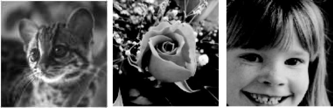
FIGURE 120.4
Input images. From left to right, original shadow 1, shadow 2, and secret images, respectively.
4.5.2 Results
Figure 4.16 shows the three input images. Each image corresponds to the shadow 1, shadow 2, and secret image, respectively, from left to right. Figure 4.17 gives the encrypted shadow 2 (above) and the secret image reconstructed by superimposing the output shadows (below). They are generated with 15 ՠ15 physical subpixels per pixel. For comparison, the shadow 2 (above) and reconstructed secret images (below) generated with the straightforward density pattern are depicted in Figure 4.18. The images in Figure 4.18 contain 3 ՠ3 subpixels per pixel, a practical number of subpixels considering the superimposition by human hands.
The method is possible to generate quite pleasant results of high image quality, especially with smoother shading of the petals and the background stems, or the whiskers and stripes of the cat. This is because the method can express at least 226 = (15 ՠ15 + 1) gray levels, which means that the resulting images can almost fully express the gray levels of the input images. Moreover, the encrypted shadow images can be superimposed by human hands with little difficulty, as they allow more misalignment tolerance.
4.6 Conclusions
This chapter explained extended visual cryptography handling photograph images. First, we overlooked the three basic visual cryptography schemes for binary images, namely, the Visual Secret Sharing Scheme, the Extended Visual Cryptography Scheme, and Random Grids. Some fundamental concepts for incorporating photographs into visual cryptography, such as halftoning techniques, some parameters related to image quality, and issues for handling photographs are observed. Then we surveyed approaches for handling photograph images, most of which are aimed at improving image quality. Finally, we have discussed one the most unique approaches proposed by Nakajima and Yamaguchi [29]. Although the method does not guarantee perfect security, it can generate very pleasant results of high image quality while maintaining misalignment tolerance.

FIGURE 121.4
Examples of resulting images. The upper image is the encrypted shadow 2 and the lower image is the secret image reconstructed by superimposing two shadows by computer simulation.

FIGURE 122.4
Examples of the output with density pattern using 3 × 3. The upper image is the encrypted shadow 2 and the lower image is the secret image reconstructed by superimposing the two shadows by computer simulation.
Bibliography
[1] G. Ateniese, C. Blundo, A. De Santis, and D.R. Stinson. Visual cryptography for general access structure. Information and Computation, 129:86–106, 1996.
[2] G. Ateniese, C. Blundo, A. De Santis, and D.R. Stinson. Extended capabilities for visual cryptography. Theoretical Computer Science, 250:143–161, 2001.
[3] E. Biham and A. Itzkovitz. Visual cryptography with polarization. In The Rump Session of EUROCRYPTf98. Available at http://www.cs.technion.ac.il~biham/Reports/visual.ps.gz, 1998.
[4] C. Blundo, A. De Santis, and M. Naor. Visual cryptography for grey level images. Information Processing Letters, 75:255–259, 2000.
[5] C.C. Chang and T.X. Yu. Sharing a secret gray image in multiple images. In International Symposium on Cyber Worlds, pages 230–237. 2002.
[6] Y.F. Chen, Y.K. Chan, C.C. Huang, M.H. Tsai, and Y.P. Chu. A multiple-level visual secret-sharing scheme without image size expansion. Information Sciences, 177((21):4696–4710, 2007.
[7] S. Cimato, R. De Prisco, and A. De Santis. Colored visual cryptography without color darkening. In Lecture Notes in Computer Science 3352 (Intl. Conference on Security in Communication Networks), pages 235–248, 2005.
[8] R.W. Floyd and L. Steinberg. An adaptive algorithm for spatial grayscale. In Society for Information Display, 17((2):75–77, 1976.
[9] M.S. Fu and O.C. Au. Data hiding in halftone images by stochastic error diffusion. In Intl. Conference on Acoustics, Speech, and Signal Processing, pages 1965–1968, 2001.
[10] M.S. Fu and O.C. Au. A novel method to embed watermark in different halftone images: Data hiding by conjugate error diffusion (DHCED). In Intl Conference on Acoustics, Speech, and Signal Processing, volume III, pages 529–532, 2003.
[11] R.C. Gonzalez and R.E. Woods. Digital Image Processing, Third Edition. Pearson Education International, 2010.
[12] Y.C. Hou. Visual cryptography for color images. Pattern Recognition, 36((7):1619–1629, 2003.
[13] T. Ishihara and H. Koga. A visual secret sharing scheme for color images based on meanvalue-color mixing. IEICE Trans. on Fundamentals, E86-A(1):194–197, 2003.
[14] R. Ito, H. Kuwakado, and H. Tanaka. Image size invariant visual cryptography. IEICE Trans. on Fundamentals, E82-A(10):2127–2177, 1999.
[15] M. Iwamoto and H. Yamamoto. The optimal n-out-of-n visual secret sharing scheme for gray-scale images. IEICE Trans. on Fundamentals, E85-A(10):2238–2247, 2002.
[16] J.F. Jarvis, C.N. Judice, and W.H. Ninke. A survey of techniques for the display of continuous tone pictures on bilevel displays. Computer Graphics and Image Processing, 5((1):13–40, 1976.
[17] O. Kafri and E. Keren. Image encryption by multiple random grids. Optics Letters, 12((6):377–379, 1987.
[18] H.R. Kang. Digital Color Halftoning. SPIE Optical Engineering Press, IEEE Press, 1999.
[19] I. Kang, G.R. Arce, and H.K. Lee. Color extended visual cryptography using error diffusion. In Intl. Conference on Acoustics, Speech and Signal Processing, pages 1473–1476, 2009.
[20] H.J. Kim and Y. Choi. A new visual cryptography using natural images. In Intl. Symposium on Circuits and Systems, pages 5537–5540, 2005.
[21] K.T. Knox. Digital Watermarking Using Stochastic Screen Patterns. US Patent No. 5,734,752, 1998.
[22] H. Koga and H. Yamamoto. Proposal of a lattice-based visual secret sharing scheme for color and gray-scale images. IEICE Trans. on Fundamentals, E81-A(6):1262–1269, 1998.
[23] S.S. Lee, J.C. Na, S.W. Sohn, C. Park, D.H. Seo, and S.J. Kim. Visual cryptography based on an interferometric encryption technique. ETRI Journal, 24((5):373–380, 2002.
[24] R. Lukac and K.N. Plataniotis. Bit-level based secret sharing for image encryption. Pattern Recognition, 38((5):767–772, 2005.
[25] E. Myodo, K. Takagi, S. Miyaji, and Y. Takishima. Halftone visual cryptography embedding a natural grayscale image based on error diffusion technique. In Intl. Conference on Multimedia and Expo, pages 2114–2117, 2007.
[26] E. Myodo, K. Takagi, and A. Yoneyama. Auto tone mapping method to generate and decode high contrast halftone images in visual cryptography. IEICE Technical Report, IE2009-53, 109((149):25–30, 2009. (in Japanese)
[27] D. Naccache. Colorful Cryptography—a purely physical secret sharing scheme based on chromatic filters. In The French-Israeli Workshop on Coding and Information Integrity. Available at http://www.gemplus.com/smart/rd/publications/ps/Nac94col.ps. 1994.
[28] M. Nakajima and Y. Yamaguchi. Extended visual cryptography for natural images. Journal of WSCG, 10((2):303–310, 2002.
[29] M. Nakajima and Y. Yamaguchi. Enhancing registration tolerance of extended visual cryptography. Journal of Electronic Imaging, 13((3):654–662, 2004.
[30] M. Nakajima and Y. Yamaguchi. Device-dependent color neutralization method. In Color Imaging X, SPIE volume 5667, pages 581–588, 2005.
[31] M. Naor and A. Shamir. Visual cryptography. In Lecture Notes in Computer Science 950 (Advances in Cryptology- EUROCRYPTf94), pages 1–12, 1994.
[32] M. Naor and A. Shamir. Visual cryptography II: Improving the contrast via the cover base. In Lecture Notes in Computer Science 1189 (Security Protocols), pages 197–202, 1997.
[33] K. Oka, Y. Nakamura, and K. Matsui. Embedding signature into a hardcopy image using micro-patterns. IEICE Trans. on Information and Systems, J79-D-II(9):1624–1626, 1996. (in Japanese)
[34] K. Oka, Y. Nakamura, and K. Matsui. Embedding signature into a hardcopy image of dithered image. IEICE Trans. on Information and Systems, J80-D-II(3):820–823, 1997. (in Japanese)
[35] V. Rijmen and B. Preneel. Efficient colour visual encryption or “Shared colors of Benetton.” In The Rump Session of EUROCRYPTf96. Available at http://www.iacr.org/conferences/ec96/rump/preneel.ps.gz 1996.
[36] S.J. Shyu. Efficient visual secret sharing scheme for color images. Pattern Recognition, 39((5):866–880, 2006.
[37] S.J. Shyu. Image encryption by random grids. Pattern Recognition, 40((3):1014–1031, 2007.
[38] R. Ulichney. Digital Halftoning. The MIT Press, 1987.
[39] E.R. Verheul and H.C.A. van Tilborg. Constructions and properties of k out of n visual secret sharing schemes. Designs, Codes and Cryptography, 11((2):179–196, 1997.
[40] D.Q. Viet and K. Kurosawa. Almost ideal contrast visual cryptography with reversing. In Lecture Notes in Computer Science 2964 (Topics in Cryptography), pages 353–365, 2004.
[41] S.G. Wang. Digital Watermarking Using Conjugate Halftone Screens. US Patent No. 5,790,703, 1998.
[42] C.W. Wu, G. Thompson, and M. Stanich. Digital watermarking and steganography via overlays of halftone images. Electrical Engineering IBM Research Report, RC23267 (W0407-013), pages 1–12. 2004.
[43] X. Wu, D.S. Wong, and Q. Li. Threshold visual cryptography scheme for color images with no pixel expansion. In Intl. Symposium on Computer Science and Computational Technology, pages 310–315, 2009.
[44] C.N. Yang and C.S. Laih. New colored visual secret sharing schemes. Designs, Codes and Cryptography, 20((3):325–335, 2000.
[45] C.N. Yang and T.S. Chen. Extended visual secret sharing schemes: Improving the shadow image quality. International Journal of Pattern Recognition and Artificial Intelligence, 21:879–898, 2007.
[46] C.N. Yang and T.S. Chen. Colored visual cryptography scheme based on additive color mixing. Pattern Recognition, 41((10):3114–3129, 2008.
[47] Z. Zhou, G. R. Arce, and G. Di Crescenzo. Halftone visual cryptography. IEEE Trans. on Image Processing, 15((8):2441–2453, 2006.
1Originally a concept of average transmission was used both in [17] and [37] instead of average opacity. However, it is slightly confusing because people usually use 0 for a transparent (white) pixel and one for an opaque (black) pixel in visual cryptography studies. Thus, here we use the term average opacity.
2Only Cover can be physically realized with transparencies and opaque sheets. Physical implementation of XOR is possible by exploiting polarization.
3In [28], Nakajima and Yamaguchi discussed pixel transparency instead of opacity. However, as we already indicated, people usually use 0 for a transparent (white) pixel and 1 for an opaque (black) pixel in visual cryptography studies. Thus, here we consider pixel opacity rather than pixel transparency.