
2
Visual Cryptography for Color Images
Stelvio Cimato
Università, degli Studi di Milano, Italy
Roberto De Prisco
Università di Salerno, Italy
Alfredo De Santis
Università di Salerno, Italy
CONTENTS
2.1 Introduction
The key property used to construct visual cryptography schemes for black and white images is the following: if we superpose transparencies with black and white pixels, the resulting pixel that our eyes see is black if at least one of the superposed pixels is black and is white if all the superposed pixels are white. Such a property can be rephrased as follows: the possible “state” for the pixels can be represented with a bit, using 0 for white and 1 for black, and the human visual systems performs an OR of the input pixels in order to reconstruct the secret pixels.
This key property does not easily extend to colored pixels. With colored pixels the state of each pixel cannot be represented anymore with a single bit and the “reconstruction” operation performed by our eyes is much more complicated than a simple OR.
In this chapter we will first describe the difficulties that arise from the superposition of colored pixels and then we review the work on visual cryptography for colored images.
We assume that the reader is familiar with (at least the basics of) black and white visual cryptography.
2.2 Color Superposition
What happens when we stack together two transparencies so that two pixels get superposed? What is the color that the human eyes see as the result of this superposition? Figure 2.1 illustrates the superposition operation with two examples. In the first one we are using black and white pixels: the superposition of a black pixel with a white pixel yields a black pixel. In the second example, we are using colored pixels: the superposition of a yellow pixel with a magenta pixel yields a red pixels.
Using only black and white images the result of the superposition of pixels printed on transparencies is straightforward: it is black if and only if at least one of the pixels is black.
The answer to the same question gets much more complicated when we use colors. In order to understand what happens when we superpose transparencies with colored pixels we have to talk a bit about light and color theory.
2.2.1 Color Vision and Color Models
Modern understanding of light and color vision is based upon the advances of several great scientists, such as the ones due to Newton. Thanks to them today we have a good understanding of light and colors; the topic is quite complex and a rigorous and detailed explanation goes beyond the scope of this chapter. However, we will try to explain the basic properties of light and colors because they are crucial for any visual cryptography scheme that deals with color images.
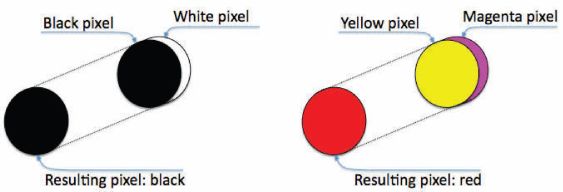
FIGURE 2.1
(See color insert.) Pixels superposition: black and white (left) and colored (right).
Roughly speaking, light consists of electromagnetic energy with wavelengths in the approximate range of 350–750 nm, as shown in Figure 2.2. The visible range represents only a small fraction of the full electromagnetic spectrum.
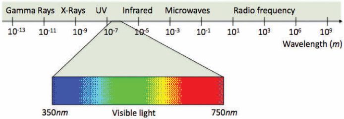
FIGURE 2.2
(See color insert.) Electromagnetic spectrum.
When a particular wavelength in such a range hits the retina in our eyes, it is perceived as a color. In the visible range, shorter wavelengths are perceived as bluish colors, middle wavelengths as greenish colors, and higher wavelengths as reddish colors. When our eyes are hit by several wavelengths we perceive a color that is a sort of “sum” of the wavelengths. If the eyes are hit by all the visible wavelengths, the perceived color is white. That is, a (pure) white light consists of all the visible wavelengths.
The expressions “red light,” “yellow light,” etc., are technically incorrect, but we will often use them to mean a light whose wavelength is perceived as red, yellow, etc. Since each wavelength corresponds to a color, there are infinite colors, one for each possible wavelength.
An object appears to be of a particular color because when light hits the object some light is absorbed, that is some wavelengths are absorbed; the remaining wavelengths are perceived by our eyes. When light hits an object it can also be reflected (or pass through the object). An object of a particular color χ, has strong absorption properties for the wavelengths that do not correspond to χ while it reflects the light with color χ. For example, an object appears yellow (when hit by a white light) because it reflects the yellow light and absorbs most strongly in the other parts of the spectrum. In the case of a transparency, the light that is not absorbed instead of getting reflected passes through the transparency.
A color model is a formal model that allows us to represent all (or some of) the possible colors. One of the most used color model is the one called the “additive color model.” With this method three primary colors (usually red, green, and blue) are mixed to obtain other colors. Figure 2.3 shows this model with the primaries red, green, and blue; the colors yellow, cyan, and magenta are produced when two of these primaries overlap. Varying the “intensity” of each primary in the mixing we can obtain many other colors.
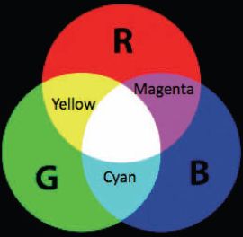
FIGURE 2.3
(See color insert.) Additive color model with primaries red, green, and blue.
The set of all possible colors that we can obtain depends on the three primary colors that we use. Any three colors can be used as primaries; the range of colors that we obtain is the gamut of those primaries. Unfortunately, no three primary colors exist so that their gamut corresponds to the set of all possible colors; however by choosing red, green, and blue as primaries we obtain a very large number of colors in their gamut. This is why these three colors have been chosen for the additive color model and the model is often called Red, Green, and Blue (RGB). Most displays use this model.
Another color model is the “subtractive color model,” also called the Cyan, Magenta, and Yellow (CMY) model. In this case the colors are obtained with a subtractive technique that starts from a white light and subtracts wavelengths corresponding to the three colors cyan, magenta, and yellow. Figure 2.4 shows the CMY model.
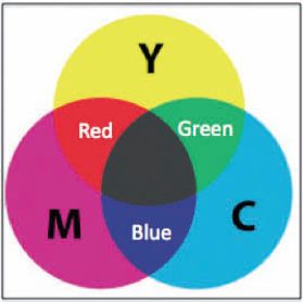
FIGURE 2.4
(See color insert.) Subtractive color model with primaries cyan, magenta, and yellow.
Most modern printers use this model, often exploiting an additional black ink; an additional K in the name CMYK indicates the use of the extra black ink. Notice that we can obtain black by using all three inks (cyan, magenta, yellow) together; however it is more efficient to cover a pixel with just black ink, rather covering it with the three inks cyan, magenta, and yellow.
In the additive model we start from the absence of light, which gives the black color, and we add light to obtain other colors with the extreme case being the white color obtained when we add all possible wavelengths. In the subtractive model we start from a white light and we subtract wavelengths to obtain other colors with the extreme case being the color black obtained when we take out all possible wavelengths.
If we are not very picky, and a discussion about this aspect goes beyond the scope of this chapter, we can say that the RGB and the CMY models are equivalent and complementary. Indeed an ink with the color cyan absorbs the light corresponding to the red color, an ink with the color magenta absorbs the light corresponding to the green color, and an ink with the color yellow absorbs the light corresponding to the blue color. Because of this, for both models, we will formally represent a color χ as a triple (x, y, z), where x, y, and z denote the amount of red, green, and blue, respectively, that χ consists of. The amount of each type of light (red, green, blue) is described by an integer in the range [0, L]. With this setting, we can produce (L + 1)3 different colors, which, for L sufficiently large, are enough to approximate all colors that the human eyes are able to distinguish. Typically, for computers, we have L = 255. To make things easier, throughout this chapter, we use L = 100.
Each of the components x, y, and z can be seen as a filter that lets pass through only some light. The color (0,0,0), which we will denote also with the symbol ”●,” is the black color: indeed all filters are 0, meaning that there is no light left. The color (100, 100, 100), which we will denote also with the symbol “○,” is white because no light is absorbed by the filters. The colors red, green, and blue are represented, respectively, by (100, 0, 0), (0, 100, 0), and (0, 0, 100); we will refer to these colors also as R, G, and B, respectively. The colors cyan, magenta, and yellow are represented, respectively, by (0, 100, 100), (100, 0, 100), and (100, 100, 0); we will refer to these colors also as C, M, and Y, respectively. The color (50, 0, 0) is also a red, because that is the only component present, but it is darker since some red light has been absorbed. The higher the value of the component, the lighter is the color. If all components are equal, i.e., (x, x, x), then the resulting color is a gray whose intensity depends on x: the smaller is x, the darker is the gray.
Recall that this representation works fine both for the additive model and for the subtractive model. In the additive model we start from (0, 0, 0) and add light while in the subtractive model we start from (100, 100, 000) and subtract light.
In the context of visual cryptography we can think of the transparencies as filters; starting from a white light we “subtract” some light applying filters (the transparencies). The remaining light determines the color that we see when superposing several transparencies. At this point it is worth emphasizing that “white” on a transparency is actually “transparent.” We assume to start with a pure white light; if the transparency does not have any ink on it, then the white light just passes through the transparency and we see white.
What is the color of the pixel resulting from the superposition of one or more transparencies?
When we drop some ink on the transparency and hold the transparency to the light we see the color that the ink lets pass through. When more transparencies get stacked together, the color of the resulting pixel depends on the absorption properties of the inks on all of the transparencies.
Let χ1 = (x1, y1, z1) and χ2 = (x2, y2, z2) be two colors and assume that two pixels of color χ1 and of color χ2 are printed on two different transparencies.
The following operator add describes the color superposition operation:
Notice that taking into account only the inks that we have used for each transparency is a simplification: the perception of the final color depends also on the material of the transparencies and the aberrations that the stack of transparencies produces. Moreover, it is likely that the initial light we start with is not a pure white light and that there are also other sources of light in the environment. However, the add operator is a quite good approximation.
The add operation is commutative and thus the order in which we superpose the colors is irrelevant. As expected, it results that add(Y, M) = R, add(R, G) = Y, add(Y, M, C) = ●. Figure 2.5 shows some other examples of superposition of colored pixels.
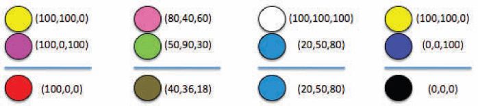
FIGURE 2.5
(See color insert.) Examples of pixels superposition.
The add operator can be easily extended to any number of pixels. Indeed since the operation is commutative it is enough to add any two pixels each time until we get to one pixel. Let χ1 = (x1, y1,z1), χ2 = (x1, y2, z2), … ,χn = (xn, yn, zn) be the colors of the pixels. The color of the pixel that results from the superposition is:
where
Figure 2.6 shows examples of superpositions with 3 pixels.

FIGURE 2.6
(See color insert.) More examples of pixels superposition.
2.2.2 Lattices
Some papers (e.g., [7]) use finite lattices to formalize the properties of the superposition of colored pixels. A finite lattice is a partially ordered set for which any two elements of the set have a least upper bound and a greatest lower bound. We can use a lattice to describe a color model.
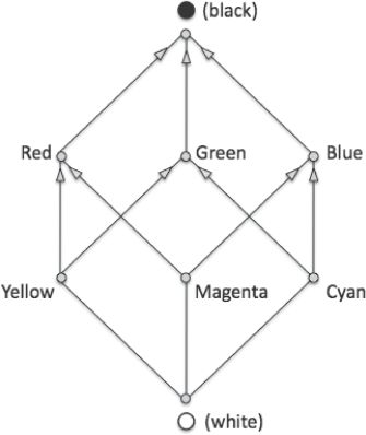
FIGURE 38.2
Lattice for the RGB and CMY color models.
In the additive model the superposition of two colored pixels corresponds to the greatest lower bound while in the subtractive color model the superposition corresponds to the least upper bound. The choice of a particular lattice is equivalent to the choice of a color model. For example, the lattice in Figure 2.7 is equivalent to the color model that uses the following 8 colors: black, white, R, G, B, C, M, and Y. Notice that this particular set of colors is closed under the superposition operation. It is worth emphasizing that this lattice is not equivalent to the RGB and CMY models: it only considers the 8 colors with zero or full intensity while the RGB and CMY models have many more colors.
2.2.3 The Darkening Problem
When we superpose pixels having the same color, unless we have zero or full intensity components, the resulting pixel is a darker version of the original color. This is because each transparency is a filter that absorbs some light, except when the transparency is white, and thus the resulting pixel is darker. Figure 2.8 shows examples of superposition of pixels with the same color, a light grey. As can be noticed in the figure, as we add more pixels the resulting color becomes darker, with the limit being a full black.
We will refer to this problem as the darkening problem. Some of the schemes that we will describe later superpose pixels with the same color, but ignore the darkening problem.
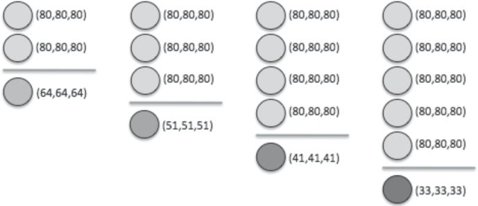
FIGURE 39.2
The darkening problem.
2.2.4 The Annihilator Color
Since for any color χ we have that add(χ, ●) = ●, in many visual cryptography schemes for color images the black color is often used to “cover up” other colors so that they don’t show up in the reconstructed image. For this reason we call the black color the “annihilator” color. The presence of the annihilator color in the reconstructed image has no meaning and thus the observer has to ignore it. The use of the annihilator color is not a problem from a formal point of view but the visual effect is not good: in many cases the presence of the annihilator color in the reconstructed image is overwhelming (e.g., 90% of the image) and thus it is not reasonable to assume that the observer can recognize the secret image. This is clearly a problem if we want to share images, but it doesn’t rule out some applications as we will see in later sections. We remark that the annihilator color, has nothing special: it is just the black color! If the secret image contains black pixels, then we will not be able to distinguish amongst the black pixels in the reconstructed image which ones were originally black and which ones were annihilated.
2.2.5 The Identity Color
Color ○ is the “identity” color, in the sense that for any color χ we have that add(χ, ○) = χ. In some schemes the identity color is used, together with the annihilator color, as a special color. Recall that that in the context of visual cryptography white is actually transparent.
2.3 Formal Models for Colored VCS
In this section, we discuss the formal model for color visual cryptography, or Color-VC for short. We first recall the basic properties of the formal model for black and white visual cryptography, B&W-VC for short, that will be needed also for the case of color images and then we dwell upon the problems that need to be tackled in order to define a formal model for Color-VC.
2.3.1 The Models for B&W-VC
For B&W-VC the formal models used in the literature are all equivalent (with variations on the metrics used for evaluation, like for example the contrast of the scheme). The two key properties, that will be needed also for color images, are:
the safety property, which guarantees that nonqualified sets of participants are not able to reconstruct the secret image;
the contrast property, which guarantees that qualified sets of participants are able to reconstruct the secret image.
To evaluate visual cryptography schemes the most important metric is the pixel expansion, that is the number of subpixels used in the reconstructed image for each pixel of the secret image.
Another important measure for the evaluation of B&W-VC schemes is the contrast of the reconstructed image that can be defined as a function of the contrast property. Several contrast properties and metrics can be found in literature for B&W-VC. We refer the reader to the relevant papers about the contrast (see for example [5]).
With the exception of the definition of the contrast, the formal model for B&W-VC is pretty standard.
2.3.2 The Models for Color-VC
For color images even the model becomes difficult to define. Do we start with a prespecified palette, perhaps the one used in the secret image, or do we consider all possible colors? What color model do we consider? Do we consider the darkening problem? Is the palette closed under the superposition operation? That is, if we start with a prespecified palette, do we consider the possibility that the reconstructed image contains colors that are not in the original palette? How do we define the contrast property for color images and what is the contrast metric? Do we allow the use of the annihilator color? How do we account for it in the contrast property?
In the following, we discuss all these issues. We start by defining the secret and the shares palettes as follows:
Secret palette: this is the set of colors used in the secret image. This is a finite set of c colors (we can have at most one color per pixel). To make notation easier we will denote these colors simply with the set of integers {1, 2, …, c}. For the colors white, black, red, green, blue, cyan, magenta, and yellow we will also use the corresponding symbol (○, ●, R, G, B, C, M, Y) instead of the palette index.
Shares palette: this is the set of colors that we can print on the shares or obtain by superposing printed shares. The shares palette might be the same as the original palette, or it might be augmented with some (or even many) other colors. Most of the schemes used in the literature augment the shares palette with the colors ○ and ●. We denote the colors in the shares palette with the set of integers {1, 2, …, d}. When the shares palette is a superset of the secret palette (this is the case in almost all of the scheme presented in this chapter) we have that d ≥ c and to simplify the notation we assume, without loss of generality, that the first c colors of the shares palette are exactly those in the secret palette.
The secret image consists of a collection of pixels, each one with a color of the secret palette. As for B&W-VC, each pixel of the secret image is encoded in the shares into a certain number m of subpixels. Such an integer m is the pixel expansion of the scheme.
In order to define a scheme we need to specify the qualified and the nonqualified set of participants. There are n participants. For simplicity we consider only the case of threshold schemes: Any set of at least k participants is a qualified set, while any set with less than k participant is a nonqualified set of participants.
In order to share each pixel of the secret image a trusted third party has to create and distribute shares to the n participants. The creation of the shares is defined using distribution matrices. These are c collections (multisets) of n × m matrices C1, C2, …,Cc, whose elements are in the shares palette.
To share a secret pixel of color i, the dealer randomly chooses one of the matrices in Ci and distributes row j to participant j. Thus, the chosen matrix defines the m subpixels in each of the n transparencies.
An example of distribution matrix is the following:
In this case, there are n = 4 participants (number of rows in the distribution matrices) and the pixel expansion of the scheme is m = 5 (number of columns in the distribution matrices). If D is the matrix selected for the distribution of the shares then the 5 subpixels in the first share will have colors 1●1M1, while those in the second share will have colors R11○2.
Given a distribution matrix M and a set of participants X, we denote with M|X the submatrix of M obtained by considering only the rows of M corresponding to the participants in X.
As for the black and white case, the definition of a scheme must satisfy the security and the contrast properties:
Security property: Given a forbidden set X, |X| < k, the c collections of |X| × m matrices, Di, i = 1, 2, …, c, consisting of M|X for each M ∈ Ci, contain the same matrices with the same frequencies. This property guarantees that a forbidden set of participants has no information on the secret image.
Contrast property: The contrast property has to guarantee that the secret image will be visible for a qualified set of participants. For B&W-VC this property uses two thresholds ℓ and h, with ℓ < h, and requires that when the secret pixel is white, the number of black subpixels in the reconstruction is at most ℓ and when the secret pixels is black, the number of black subpixels is at least h. Many papers that deal with color images generalize this definition requiring that in the reconstructed pixel there are at least h subpixels of color i, where i is the color of the secret pixel, and for any other color j ≠ i there are at most ℓ subpixels with color j. Notice that this definition can be used only if the shares palette is equal to the secret palette. Moreover, it allows the possibility that the reconstructed pixel is made up of an overwhelming majority of subpixels with a wrong color. For example if h = 4, l= 3, and c = 10 it is possible to have in the reconstructed pixel only 4 subpixels with the right color while other 27 = 3 • 9 have (mixed) wrong colors. The annihilator color ● can be present without any restriction.
Probably a better definition of the contrast property should require that in the reconstructed image there be at least h subpixels with the right color and at most ℓ subpixels with wrong colors. That is, the number of subpixels with the right color should be greater than the number of subpixels with a wrong color (counting all the subpixels with wrong colors).
We will refer to the first property as the weak contrast property and to the second one as the strong contrast property.
Next, we provide a formalization of such properties. Define the add(M) for a distribution matrix M to be the vector whose jth component is the add of column j in M and define wi(v) for a vector v to be the number of elements equal to color i, for i = 1, 2, …, c, that is for any color in the secret palette. Moreover we define to be the number of elements in v different from color i and from the annihilator color.
Weak contrast property: There must exist h and í, integers 0 ≤ ℓ < h ≤ m, such that given a qualified set X, |X| = k, for any M ∈ Ci, it holds that wi(add(M|X)) ≥ h and wj(add(M|X)) ≤ ℓ for any j in the shares palette and j = i. Note that the annihilator color is not considered, that is, it is allowed that many pixels be ●.
Strong contrast property: There must exist h and í, integers 0 ≤ ℓ < h ≤ m, such that given a qualified set X, |X| = k, for any M ∈ Ci, it holds that wi(add(M|X)) ≥ h and . Also in this case the annihilator color can be present without restriction.
In the black and white case, the thresholds ℓ and h, together with the pixel expansion m have been used to define several variants of the contrast metric, such as α = h−ℓ, α = (h−ℓ)/m, and α = (h−ℓ)/(h+ℓ). Similar measures have been used for color schemes and we will specify the definition of the contrast when presenting the schemes. However, for Color-VC schemes we need to account for the presence of the annihilator color in the reconstructed image and this makes the contrast less important. We will evaluate the annihilator presence that we can define as β = b/m, where b is the number of pixels that get annihilated in the reconstruction process.
2.3.3 The SC, ND, and General Models
The schemes that we will review in the rest of the chapter can be classified, based on the formal model that they use, into three classes. In the next paragraph we define three formal models for Color-VC.
The SC (Same Color) model.
The SC model does not allow the superposition of pixels with different colors, with the exception of the identity (○) and the annihilator (●) colors. Hence, the shares have to be constructed in such a way that each column in the distribution matrices have elements taken from the set {i, ○, ●}, for some color i. Thus, when we superpose several transparencies, we never have a pixel of color i superposed with a pixel of color j.
Moreover the darkening problem is ignored. That is, it is assumed that superposing several pixels with color i, the resulting color is still i.
An example of a distribution matrix for such kinds of schemes is the following (we have used three colors, denoted with the numbers 1 , 2, and 3):
As can be noted, in each column, we either have colors ○, ●, or pixels with a color χ = 1, 2, or 3. We never have a column that mixes two different colors in the set {1, 2, 3}.
This restriction and the fact that the darkening problem is ignored avoids the complications that derive from color superposition.
The ND (No Darkening) Model.
The ND model is as the SC model but it considers the darkening problem. Thus, again we cannot superpose pixels with different colors, but if we superpose several pixels with the same color we get a darker version of that color.
The General Model.
In the General model, there are no restrictions about the superposition of pixels and the superposition operation satisfies the real properties of color superposition. This means the darkening problem is considered. Very few schemes have been defined for this model.
2.3.4 Base Matrices
Given a matrix B, we denote by C(B) the set of matrices obtained by permuting in all possible ways the columns of B. In most schemes, the c collections Ci are obtained by fixing c matrices Bi, i = 1, 2, …, c, and letting C = C(Bi). The matrices Bi are called the “base matrices.” Base matrices constitute an efficient representation of a scheme. Indeed, the dealer has to store only the base matrices and in order to randomly choose a matrix from C(Bi) it has to randomly choose a permutation of the columns of the base matrix Bi.
Notice that the security property for a base matrices scheme is equivalent to: Given a forbidden set X, the matrices Bi|X, for i = 1, 2, …, c are the same up to a permutation of the columns.
2.4 Schemes for the SC Model
In this section, we review the known schemes for the SC model. Verheul and van Tilborg [10] were the first to consider visual cryptography schemes for color images. Their model is equivalent to the SC one; as we will see shortly their model requires a special property, which can be easily implemented using the SC model. The schemes of [10] were improved first by [2] and then by [7, 11]. Paper [3] provides a lower bound on the pixel expansion and also the construction of (n, n)-threshold schemes that achieve the lower bound. It turns out that the (n, n)-threshold schemes of [7, 11] also have optimal pixel expansion, which means that the schemes of [3] and those of [7, 11] are equivalent.
2.4.1 The VV Schemes
The model considered in [10], which we will call the VV model, requires a special property: if we superpose pixels with different colors then the resulting pixel is black. As we have explained earlier, this property is not natural. When we superpose two pixels with different colors, we get a third color that depends on the colors of the two superposed pixels. In some particular cases the resulting color is actually black, but it is not black in most cases.
Verheul and van Tilborg propose a trick that “implements” such a property. The trick works as follows: each pixel is divided into c subpixels, where c is the number of colors in the secret image, subpixels i gets color number i, while all other subpixels get painted with black, as shown in Figure 2.9.

FIGURE 2.9
(See color insert.) The VV trick for the case of 4 colors. Subpixels with different colors are never superposed.
This trick implements the required property and makes the VV model equivalent to the SC model because in the resulting scheme subpixels with different colors are never superposed. However, to implement the trick, we have to pay an extra pixel expansion factor of c and a considerable fraction of the original pixel gets annihilated in the reconstruction.
The schemes of [10] are constructed using finite fields that satisfy certain conditions. We refer the reader to the original paper for a detailed description of the construction.
Assuming that c > 2 is a prime power, the construction produces
(k, k)-threshold schemes with c colors for any k;
(k, c − 1)-threshold schemes with c colors for k < c;
(k, c)-threshold schemes with c colors for k < c, if k − 1 and c − 1 are not relatively prime.
The pixel expansion of the schemes is m = ck; this includes the pixel expansion m = ck−1 due to the construction of the scheme and the extra c factor due to implementation of the special property of the VV model.
The reconstruction guarantees that there is at least one pixel of the original color and no pixels with other colors, that is h =1 and ℓ = 0. The contrast property property considered is the weak one. However, we note that when ℓ = 0 the weak and the strong contrast property are equivalent. The annihilator presence β = (m − 1)/m, that is only one out of the m pixels is of the original color, while the remaining m − 1 are annihilated.
As an example, we report the (3, 3)-threshold 3-color scheme. Here are the three base matrices:
The pixel expansion, that corresponds to the number of columns in the base matrices, is m = ck−1 = 32 = 9. The above base matrices work only in the vv model. Although the annihilator color is not explicitly used, it appears because of the special property. Indeed, implementing the special property using the trick suggested earlier, the base matrices become the following:
Hence, the real pixel expansion is m = ck = 33 = 27. In this particular case superposing 3 shares we get 26 black pixels out of 27 and just 1 colored pixel. That is, the annihilator presence is β = 26/27 (about 96%).
This approach doesn’t seem practicable for images, but it can be used for other applications, like sharing passwords associating, for example, a digit to each color. For example, as reported in [10], if we use pixels of diameter 0.5 cm with 9 colors we can build a (3, 9)-threshold visual scheme with 9 colors using 92 = 81 pixels for each color of the password; on a standard A4 page there is room for a 90 digit password.
2.4.2 The BDD Schemes
Blundo et al. [2] focus on schemes with maximal contrast. They consider the weak contrast property and define the contrast as α = (h − ℓ)/(h + ℓ). The following results are provided in [2]:
A first construction of c-color (2, n)-threshold Color-VC schemes with maximal contrast. The construction requires c > n.
A proof that the above condition c > n is necessary to have a maximal contrast scheme. It turns also out that, among the schemes with maximal contrast, the schemes provided by the first construction are also with optimal pixel expansion.
A second construction of c-color (2, n)-threshold Color-VC schemes. Such a construction gives a better pixel expansion with respect to the first one but the schemes are not with maximal contrast.
A construction of maximal contrast c-color (n, n)-threshold Color-VC schemes with improved pixel expansion with respect to those provided in [10].
We refer the interested reader to [2] for details about the constructions and the lower bound cited in this section.
2.4.3 The KY and YL Schemes
Koga and Yamamoto [7] and independently, Yang and Laih [11] provide (k, n)-threshold c-color schemes that improve on the pixel expansion of the schemes in [10, 2]. Here we report the construction provided in [11], but the one in [7] is equivalent.
Construction 1 The construction exploits as a building block the base matrices B○ and B● of a scheme for black and white images. In order to obtain the base matrix Bi for color i we can concatenate one modified copy of B○ with c − 1 modified copies of B●. The required modifications are the following: in B○ we substitute ○ with color i while in the c − 1 copies of B● we substitute ○ with the remaining c − 1 colors (one color per copy). The pixel expansion of the c-color scheme is c times the pixel expansion of the original black and white scheme.
As an example, consider the following (3, 3)-threshold 3-color scheme. We start with the base matrices of a (3, 3)-threshold scheme for black and white images as defined in the paper by Naor and Shamir [8] (however, the construction works with any other choice of the black and white base matrices):
Then we construct the base matrices for the 3-color scheme as follows:
Using as a building block the original (k, n)-threshold scheme provided in the paper by Naor and Shamir [8], whose pixel expansion is 2k−1, the c-color schemes so obtained have pixel expansion m = c × 2k−1. This greatly improves on the pixel expansion of [2, 10].
Finally, as observed, also in [11], we can delete from the base matrices the columns that have all pixels with color ●. Using the base matrices provided in the paper by Naor and Shamir [8], for n even we always have one such column in each base matrix, while for n odd we always have c − 1 such columns in each base matrix. Hence, the pixel expansion can be further improved to m = c × 2k−1 − 1 for n even and to m = c × 2k−1 − c +1 for n odd. This is important as we will see that for k = n this improved pixel expansion matches a lower bound proved in [3].
The contrast property considered is the weak one. The scheme have parameters h = 1 and ℓ = 0 (recall that for the special case of ℓ = 0 the weak contrast property is equivalent to the strong one). The annihilator presence is β = (m − 1)/m.
The same idea used for the construction of c-color (k, n)-threshold schemes starting from black and white (k, n)-threshold schemes, can be used also for general access structure schemes. The pixel expansion of the c-color scheme is c times the pixel expansion of the black and white scheme that we start with.
2.4.4 The CDD Schemes and a Lower Bound
Paper [3] defines the contrast as α = (h − ℓ)/m and considers the weak contrast property. The following theorems are proved in [3]:
Theorem 1 In the SC model, the optimal contrast of a c-color (n, n)-threshold scheme is
Theorem 2 In the SC model, the pixel expansion ofa c-color (n, n)-threshold scheme, for any c, n ≥ 2, is lower bounded by
Note that the above lower bound implies that the schemes of [7, 11] have optimal pixel expansion. In [3] an alternative construction of c-color (n, n)-threshold schemes with optimal pixel expansion is provided. The construction is the following:
Construction 2 Fix any color i; base matrix Ci consists of the following columns:
for r = 0, 1, …, ⌈n/2⌉ − 1 include the columns, having 2r entries equal to ● and the remaining ones of color i;
for any color j ≠ i, for include the columns having 2r − 1 entries equal to ● and the remaining ones of color j;
Below is an example for c = 3 and n = 4. For such a scheme m = 23 and α = 1/23.
Other results of [3] are
2.5 Schemes for the ND Model
In this section we describe schemes that work for the ND model. This model has been considered only in [4] where a construction for c-color (k, n)-threshold schemes is presented.
In order to have pixels with exactly the same color as the original one the schemes of [4] have the property that in any shares superposition at most one pixel is colored; all other pixels have one of the two special colors ○ or ●.
The construction uses as a building block a black and white (k − 1, k − 1)-threshold scheme.
Construction 3 Let and be the basis matrices of a (k − 1, k − 1)-threshold scheme and let m′ be the pixel expansion of such a scheme. Denote the rows of and with wi and bi, respectively:
Let and . Then let , where i ∈ {1, 2, …, c} and ϕ ∈ {○, ●} be the matrix constructed by submatrices, called “blocks,” with dimension n × m′ each consisting of the following rows: n − k (”black”) rows of m′ elements •; Each block differs from the others in the choice of the n − k “black” rows; The remaining k rows are filled with one row of elements equal to i followed in order by the k — 1 rows of
Base matrix for color i, for i ∈ {1, 2, …, c}, is given by
where + denotes the concatenation of the matrices.
An example will clarify the above construction. Let k = 3 and n = 4 and consider the matrices and given by the Naor and Shamir (2, 2)-threshold scheme [8], that is,
The F matrices will have blocks, since we have to place 1 black row in each of 4 possible positions. Hence, we have
The vertical bars identify the 4 blocks. As can be seen each block is given by 1 black row, and the remaining rows filled, in this order, by one row of i’s and the rows of (or ), from the first to the last. Using the above F matrices we can build the following 3-color (3, 4)-threshold scheme.
Construction 3 builds a c-color (k, n)-threshold scheme with pixel expansion , where m′ is the pixel expansion of the black and white scheme used as building block. The thresholds ℓ and h depend on the b&w scheme used as building block, If such a scheme is with perfect reconstruction of black pixels the resulting scheme has ℓ = 0, h ≥ 1. Notice that the contrast property satisfied is the weak one.
Using as a building block the best, with respect to the pixel expansion, b&w (k − 1, k − 1)-threshold scheme, provided in [8], whose pixel expansion is m' = 2k−2, the resulting scheme has pixel expansion
For k = n the pixels expansion is m = c2n−2. The model assumes the weak contrast property. The parameters h and ℓ are h = 1 and ℓ = 0 and the annihilator presence is β = (m − 1) /m.
We remark that the schemes of [4] are constructed with the restriction that the shares have only one colored pixel. This is not a restriction on the model but just on the kind of schemes that can be constructed. Although this limits the search space for good schemes, it guarantees that the reconstructed pixels are exactly of the same original color (and not a darker version of it).
If we consider a model that requires this special property the c-color (n, n)-threshold schemes of [4] are optimal with respect to the pixel expansion:
Theorem 3 [4] If the shares are restricted to be such that for any superposition it is possible to have at most one colored pixel, any c-color (n, n)-threshold scheme has pixel expansion m ≥ c2n−2.
Other results presented in [4]:
A construction of c-color (2, n)-threshold with pixel expansion m = c(n − 1).
A matching lower bound m ≥ c(n − 1).
A construction of c-color (2, n)-threshold with contrast . The contrast is defined as α = (h − ℓ)/m and the thresholds h and ℓ satisfy the weak contrast property.
An upper bound on the contrast . This matches the construction for k = 2.
2.6 Schemes for the General Model
In this last section we finally describe schemes for Color-VC that consider the General model, that is we consider schemes that superimpose pixels with different colors. In the rest of the section, we present several (2, 2)-threshold schemes from [7, 1] and a construction for (2, n)-threshold schemes from [1].
2.6.1 (2, 2)-Threshold Schemes
In this section, we present schemes for the particular case of k = n = 2.
Scheme 1 [7] The secret palette is {Y, C, G} while the shares palette is {Y, C, G, ○, ●}. The base matrices are:
It is easy to see that for this scheme the pixel expansion is m = 4 and we have h = 2, ℓ = 0. The annihilator presence is β =1/2 because 2 out of 4 pixels are annihilated.
Scheme 2 [7] Both the secret palette and the shares palette are {○, Y, M, C, R, G, B, ●}. The base matrices are:
For this scheme the pixel expansion is m = 8 and we have h = 1, ℓ = 0. The annihilator presence is β = 7/8 because in most cases 6 out of 8 pixels are annihilated and for the color white 7 out of 8 pixels are annihilated. Because of this, if we restrict the secret palette to {Y, M, C, R, G, B, ●} and add ○ for the shares palette the resulting scheme has h = 2 improving the contrast.
Scheme 3 [7] Both the secret palette and the shares color palette are {○, Y, M, C, R, G, B, ●}. The base matrices are:
It is easy to see that for this scheme the pixel expansion is m = 5 and we have h = 1, ℓ = 0. The annihilator presence β = 4/5 because 4 out of 5 pixels are annihilated.
Scheme 4 [1] The secret and shares palette are {R, G, B, C, M, Y}. The base matrices are:
It is easy to see that for this scheme the pixel expansion is m = 6 and we have h = 2, ℓ = 0. The annihilator presence β = 2/3 because 4 out of 6 pixels are annihilated.
2.6.2 The (2, n)-Threshold AS Schemes
In [1] a constructions of (2, n)-threshold schemes is provided. The construction uses, as a building block, the base matrix S● for the black color of the (2, n)-threshold scheme for black and white images defined in [2]. Matrix S● is defined as all the binary column-vector with weight , with the substitutions 1 ↔ ● and 0 ↔ ○. For example, for n = 4, we have
Then, to obtain the color scheme, the black and white pixels are substituted with the rows of a specific (2, 2)-threshold color scheme. For example, using the KY scheme for the set of colors {C, Y, G} with m = 4 provided in the previous section and substituting ● with the first row of the base matrix for a given color and ○ with the second row of the base matrix we get the base matrix for that color. For example, to get the base matrix for color Y for the (2,4)-threshold scheme, we substitute in the symbol ● with Y○●C and the symbol ○ with ○YC●.
The scheme that we obtain is:
2.7 Other Schemes
In [9] Shyu proposes a construction that is very similar to the one used in [7, 11]. However, the model, although for many aspects equal to the SC model, has a crucial difference: the author assumes that the color perceived by the human eyes is an “average” of the colors present in the subpixels of the reconstructed pixels. For example, if a given surface is evenly covered with red and green we should see yellow as a result. Although this is in principle true, in practice it works only if the pixels are so tiny and evenly distributed that our eyes are not able to distinguish the single pixels and perceives an average color mixing the two primary colors. What really happens is that our eyes perceive the mixture of red and green. However, this does not mean that we cannot use this model. We have to accept the fact that a secret color (yellow, for example) is reconstructed as a mixture of other colors (red and green, for example). This model allows building schemes with a better pixel expansion, namely m = ⌈log c⌉ × 2n−1. The contrast properties that we have used throughout this paper are not applicable to this model.
In [6] Hou proposes a method that first splits the secret image into the cyan, magenta, and yellow components and then uses ad-hoc (2, 2)-threshold schemes to share those components. Although the paper claims that this method is easily extensible to the (k, n)-threshold scheme it is not clear how to use the ad-hoc (2, 2)-threshold schemes for the general case of the (k, n)-threshold scheme. A proof of the security property is also missing.
2.8 Conclusions
Stepping from visual cryptography for black and white images to visual cryptography for color images is not immediate. The color model poses some tricky questions that arise from the complex behavior of colors superposition. Many visual cryptography schemes for color images avoid the problem by not superposing pixels with different colors. Very few known schemes do actually exploit color superposition. In this chapter we have first emphasized the difficulties that arise from the superposition of colored pixels; then we have provided a survey of the models of visual cryptography for color images that have been considered in the literature and a survey of the schemes that have been proposed for such models.
Visual cryptography for black and white images has been thoroughly studied. The case of color images is still pretty much unexplored. A first direction of research concerns the definition of a reference model. We believe that the General model is the one that best represents the real world. All the models proposed in the literature lack a well-defined notion of contrast, which is a very important measure for the evaluation of the schemes. A second direction of research concerns the search for schemes that do use the properties of color superposition. The construction of schemes for color images seems to be much more difficult than for black and white images.
Bibliography
[1] A. Adhikari and S. Sikdar. A new (2,n)-visual threshold scheme for color images. In Proceedings of the Indocrypt 2003, volume 2904, pages 148–161. Springer Verlag, LNCS, 2005.
[2] C. Blundo, A. De Bonis, and A. De Santis. Improved schemes for visual cryptography. Designs, Codes and Cryptography, 24:255–278, 2001.
[3] S. Cimato, R. De Prisco, and A. De Santis. Optimal colored threshold visual cryptography schemes. Designs, Codes and Cryptography, 35((3):311–335, 2005.
[4] S. Cimato, R. De Prisco, and A. De Santis. Colored visual cryptography without color darkening. Theoretical Computer Science, 374(1-3):261–276, 2007.
[5] P.A. Eisen and D.R. Stinson. Threshold visual cryptography schemes with specified whitness levels of reconstructed pixels. Designs, Codes and Cryptography, 25:15–61, 2002.
[6] Y.C. Hou. Visual cryptography for color images. Pattern Recognition, 36:1619–1629, 2003.
[7] H. Koga and H. Yamamoto. Proposal of a lattice-based visual secret sharing scheme for color and gray-scale images. IEICE Trans. on Fundamentals of Electronics, Communication and Computer Sciences, 81-A(6):1262–1269, 1998.
[8] M. Naor and A. Shamir. Visual cryptography. In Proceedings of the Eurocrypt 1995, volume 950, pages 1–12. Springer Verlag, LNCS, 1995.
[9] S. J. Shyu. Efficient visual secret sharing scheme for color images. Pattern Recognition, 35:866–880, 2006.
[10] E.R. Verheul and H.C.A. van Tilborg. Constructions and properties of k out of n visual secret sharing schemes. Designs, Codes and Cryptography, 11((2):179–196, 1997.
[11] C.N. Yang and C.A. Laih. New colored visual secret sharing schemes. Designs, Codes and Cryptography, 20:325–335, 2000.